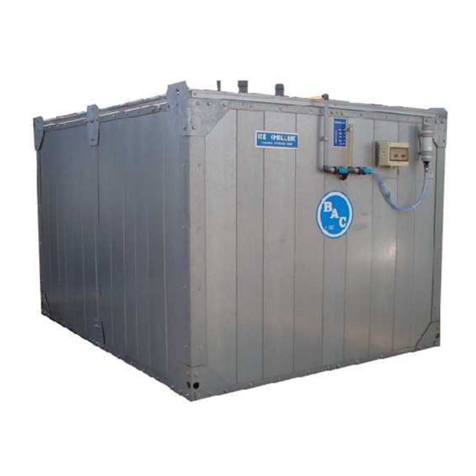
Baltimore Aircoil Company FXV3 User manual

FXV3
CLOSED CIRCUIT COOLING TOWER
CXVT
EVAPORATIVE CONDENSER
RIGGING &ASSEMBLY INSTRUCTIONS

FXV3/CXVT Rigging & Assembly Instructions –Forward Page | 2
IMPORTANT NOTICE
FXV3/CXVT should be rigged and assembled as
outlined in this bulletin.
These procedures should be thoroughly reviewed prior to the rigging
and assembly of the equipment to acquaint all personnel with
procedures to be followed and to ensure that all necessary
equipment is available beforehand.
Be sure to have a copy of the submittal package
available for reference. If you do not have a copy of this
drawing,or if you need additional information about
this unit, contact your local BAC Representative
whose name and telephone number are on a label
adjacent to the access door. The model number and
serial number ofthe unit are also located in this area.

FXV3/CXVT Rigging & Assembly Instructions –Table of Contents Page | 3
FXV3 - CLOSED CIRCUIT COOLING TOWER
CXVT - EVAPORATIVE CONDENSER
RIGGING & ASSEMBLY INSTRUCTIONS
Contents
1. Warnings and Cautions................................................................................................................................................................................. 5
Safety Precautions ..................................................................................................................................................................................... 5
Equipment Precautions.............................................................................................................................................................................. 6
2. Introduction ................................................................................................................................................................................................... 7
Safety........................................................................................................................................................................................................... 7
Shipping ...................................................................................................................................................................................................... 7
Pre-Rigging Checks.................................................................................................................................................................................... 8
Unit Weights ........................................................................................................................................................................................... 8
Anchoring ............................................................................................................................................................................................... 8
Cold Weather Operation............................................................................................................................................................................. 9
Placement.................................................................................................................................................................................................... 9
Warranties ................................................................................................................................................................................................... 9
Unit Operation............................................................................................................................................................................................. 9
3. Unit Rigging & Assembly............................................................................................................................................................................. 10
Rigging ...................................................................................................................................................................................................... 10
Section Assembly..................................................................................................................................................................................... 13
Mechanical Section’s Shipping Braces Removal on (Optional) Gear and Belt Drive Units (Optional) ............................................. 21
Plain Pipe Stub Coil Connections Nitrogen Charge Removal .............................................................................................................. 22
3. Accessory Installation ................................................................................................................................................................................. 23
General Packing & Labeling Information................................................................................................................................................ 23
ENDURADRIVE®Fan System Installation............................................................................................................................................... 24
Warnings for the ENDURADRIVE®Fan System................................................................................................................................. 24
Important Notes for the ENDURADRIVE®Fan System...................................................................................................................... 24
Access Door Platform & Ladder Installation.......................................................................................................................................... 25
Fan Deck Extension Installation.............................................................................................................................................................. 28
External Motor Gear Drive Motor Base, Platform & Ladder Installation .............................................................................................. 31
Positive Closure Damper (PCD) Hood Platform & Ladder Installation ................................................................................................ 36

FXV3/CXVT Rigging & Assembly Instructions –Table of Contents Page | 4
Internal Service Platform Railing and Ladder Installation .................................................................................................................... 39
Ladder Opening Safety Gate Installation................................................................................................................................................ 55
Cold Water Basin Connection Installation ............................................................................................................................................. 58
Fan Deck Handrail Installation ................................................................................................................................................................ 62
Multi-Section Ladder Assembly .............................................................................................................................................................. 76
Fan Deck Ladder Installation................................................................................................................................................................... 78
Motor Davit Assembly & Installation....................................................................................................................................................... 82
Positive Closure Damper (PCD) Hood Installation ................................................................................................................................ 84
Ladder Safety Cage Installation .............................................................................................................................................................. 86
Fan Cowl Extension Installation.............................................................................................................................................................. 87
Fan Guard Installation.............................................................................................................................................................................. 88
Discharge Attenuation Installation.......................................................................................................................................................... 89
Intake Attenuation Installation ................................................................................................................................................................ 90

FXV3/CXVT Rigging & Assembly Instructions –Warnings and Cautions Page | 5
1. Warnings and Cautions
Safety Precautions
•: Failure to use appropriate lifting equipment can result in a dropped load, causing severe
injury, death, and/or property damage. Lifts must be performed by qualified riggers following BAC published Rigging
Instructions, and generally accepted lifting practices. The use of a supplemental safety sling may also be required if
the lift circumstances warrant its use, as determined by the rigging contractor.
•: To prevent bodily injury or property damage, only qualified personnel qualified should
undertake the installation, operation, maintenance, and repair of this equipment. Proper care, procedures, and tools
must be used in handling, lifting, installing, operating, maintaining, and repairing this equipment
•: Equipment damage may occur if water, snow, ice, or debris has collected in the basin or
elsewhere in the unit. Such accumulations will add substantially to the equipment’s lifting weight placing equipment at
risk of damage that could result in injury. Before an actual lift is undertaken, ensure no water, snow, ice, or debris has
collected in the basin or elsewhere in the unit.
•: Equipment damage may occur if the unit is not properly anchored before operation begins.
Equipment damage could result in death or serious injury. Ensure unit is properly anchored before operation beings.
•: ENDURADRIVE®Fan System motors can induce voltage and current in the motor leads by
rotating the motor shaft, even when the motor is completely disconnected from the power source, which can lead to
severe bodily injury or death from electrical shock. Mechanically lock or tie down the fan until all wiring has been
completed and before servicing the drive system, or when performing any motor maintenance procedure.
•: Magnetic and electromagnetic fields in the vicinity of current carrying conductors and
ENDURADRIVE®Fan System motors can result in a serious health hazard to persons with cardiac pacemakers,
metal implants, and hearing aids. To avoid risk, stay away from the area surrounding the ENDURADRIVE®Fan
System motor.
•: The ENDURADRIVE®Fan System variable frequency drive may apply hazardous voltages
to the motor leads after power to the controller has been turned off. To avoid the risk of severe bodily injury or death
from electrocution, verify that the controller is incapable of delivering hazardous voltages and that the voltage at the
motor leads is zero before servicing the drive system, or when performing any motor maintenance procedure.

FXV3/CXVT Rigging & Assembly Instructions –Warnings and Cautions Page | 6
Equipment Precautions
•Each unit must be located and positioned to prevent the introduction of discharge air into the ventilation systems of
the building on which the unit is located and of adjacent buildings.
•For weight information, refer to the submittal drawing package.
•All single-cell and multi-cell units must be rigged one section at a time.
•For weight information, refer to the submittal drawing package. Any motors or accessories shipped in the cold water
basin must be removed prior to installing the upper (mechanical and coil casing) section.
•Failure to level the coil module for rigging will prevent proper engagement of rigging guides.
•ENDURADRIVE®Fan System mechanical braces are structurally required and are not removable.

FXV3/CXVT Rigging & Assembly Instructions –Introduction Page | 7
2. Introduction
Safety
Adequate precautions appropriate for the installation and location of these products should be taken to safeguard the
equipment and the premises from damage and the public from possible injury. The procedures listed in this manual must
be thoroughly reviewed prior to rigging and assembly. Read all warnings, cautions and notes.
When the fan speed of the unit is to be changed from the factory set speed, including the use of a variable speed device, steps
must be taken to avoid operating the equipment at or near the fan’s “critical speed,” which could result in fan failure and
possible injury or damage. Before changing fan speed, consult your local BAC Representative and refer to the resonant speed
identification procedure available in the operation & maintenance manual.
: Failure to use appropriate lifting equipment can result in a dropped load, causing severe injury,
death, and/or property damage. Lifts must be performed by qualified riggers following BAC published Rigging
Instructions, and generally accepted lifting practices. The use of a supplemental safety sling may also be required if the
lift circumstances warrant its use, as determined by the rigging contractor.
Shipping
Models FXV3/CXVT are factory assembled to ensure uniform quality with minimum field assembly. FXV3/CXVT models ship in
four sections per cell (one lower and three upper: each coil section ships separately) to minimize rigging and freight costs.
Contact your local BAC Representative for more information. For the dimensions and weights of a specific unit or section, refer
to the submittal drawings.
: To prevent bodily injury or property damage, only qualified personnel qualified should
undertake the installation, operation, maintenance, and repair of this equipment. Proper care, procedures, and tools
must be used in handling, lifting, installing, operating, maintaining, and repairing this equipment

FXV3/CXVT Rigging & Assembly Instructions –Introduction Page | 8
Pre-Rigging Checks
When the unit is delivered to the jobsite, it should be checked thoroughly to ensure all required items have been received and
are free of any shipping damage prior to signing the bill of lading.
The following parts should be inspected (if applicable for the unit’s configuration):
Sheaves and Belts
Interior Surfaces
Bearings
Exterior Surfaces
Bearing Supports
Louvers/Combined Inlet Shields
Fan Motor(s)
Spray Water Pumps
Fan Guard(s)
Mating Surfaces Between Sections/Modules
Fan(s) and Fan Shaft(s)
Miscellaneous Items: All bolts, nuts, washers, and sealer
tape required to assemble sections or component parts are
furnished by BAC and shipped with the unit.
Float Valve Assembly(s)
Water Distribution System
Coil Surface
Cold Water Basin
Accessories
Unit Weights
Before rigging any unit, the weight of each section should be verified from the unit submittal drawing. Unit print weights include
the final assembled unit with all accessories.
: Equipment damage may occur if water, snow, ice, or debris has collected in the basin or
elsewhere in the unit. Such accumulations will add substantially to the equipment’s lifting weight placing equipment
at risk of damage that could result in injury. Before an actual lift is undertaken, ensure no water, snow, ice, or debris
has collected in the basin or elsewhere in the unit.
Anchoring
Seven-eighths inch (7/8”) diameter holes are provided in the bottom flange of the basin section for bolting the unit to the
support beams. Refer to the suggested support drawing included in the submittal for location and quantity of the mounting
holes. The unit must be level for proper operation. Anchor bolts must be provided by others. The IBC rating is only certified
with standard anchorage locations. Using alternate anchorage locations or alternate steel supports will void any IBC wind or
seismic ratings. Contact your local BAC Representative for details.
: Equipment damage may occur if the unit is not properly anchored before operation begins.
Equipment damage could result in death or serious injury. Ensure unit is properly anchored before operation beings.

FXV3/CXVT Rigging & Assembly Instructions –Introduction Page | 9
Cold Weather Operation
These products must be protected by mechanical and operational methods against damage and/or reduced effectiveness
due to possible freeze-up. Refer to the FXV and FXV3 Closed Circuit Cooling Tower CXVB and CXVT Evaporative
Condenser Operation & Maintenance Manual at www.BaltimoreAircoil.com or contact your local BAC Representative for
recommended protection alternatives.
Placement
All evaporative cooling equipment must be placed in a location that ensures an adequate supply of fresh air into the air intakes.
When units are located adjacent to walls or in enclosures, care must be taken to ensure the warm, saturated, discharge air is
not redirected back to the air intakes. Each unit must be positioned to prevent the introduction of discharge air into the
ventilation systems of the building on which the unit is located and of adjacent buildings. For detailed recommendations on BAC
equipment layout, see our website at www.BaltimoreAircoil.com or contact your local BAC Representative.
NOTICE: Each unit must be located and positioned to prevent the introduction of discharge air into the
ventilation systems of the building on which the unit is located and of adjacent buildings.
Warranties
Please refer to the Limitation of Warranties (located in the submittal package) applicable to and in effect at the time of the sale/
purchase of these products.
Unit Operation
Prior to start-up and unit operation, refer to the unit operation & maintenance manual shipped with the unit and also available
at www.BaltimoreAircoil.com.

FXV3/CXVT Rigging & Assembly Instructions –Unit Rigging & Assembly Page | 10
3. Unit Rigging & Assembly
Rigging
NOTICE: For weight information, refer to the submittal drawing package.
NOTICE: All single-cell and multi-cell units must be rigged one section at a time.
: Failure to use appropriate lifting equipment can result in a dropped load, causing severe injury,
death, and/or property damage. Lifts must be performed by qualified riggers following BAC published Rigging
Instructions, and generally accepted lifting practices. The use of a supplemental safety sling may also be required if the
lift circumstances warrant its use, as determined by the rigging contractor.
Refer to Table 1 and Figure 1, Figure 2, and Figure 3 for each section’s required minimum spreader bar length W1
and the recommended minimum vertical dimension “H”.
Model Number
Lower Section
Plenum Section
Coil Section
H
W1
H
W1
H
W1
FXV3-1224-xxx
20’
12’
20'
12’
16’
12’
FXV3-1426-xxx
20'
14’
22'
14’
16’
14’
CXVT-x-1224-x, XECXVT-1224-x,
CXVT-x-2424-x, XECXVT-2424-x
20’
12’
20'
12’
16’
12’
CXVT-x-1426-x, XECXVT-1426-x,
CXVT-x-2826-x, XECXVT-2826-x
20'
14’
22'
14’
16’
14’
Table 1. Minimum Vertical Dimension and Spreader Bar Length for FXV3 and CXVT Units
FXV3 Model
Number
Nominal
Box Size
Coil Module
Height
FXV3-1224-20x-xx
12’ x 24’
Short
FXV3-1224-24x-xx
12’ x 24’
Short
FXV3-1224-28x-xx
12’ x 24’
Tall
FXV3-1224-30x-xx
12’ x 24’
Tall
FXV3-1224-32x-xx
12’ x 24’
Tall
FXV3-1224-36x-xx
12’ x 24’
Tall
FXV3-1426-20x-xx
14’ x 26’
Short
FXV3-1426-24x-xx
14’ x 26’
Short
FXV3-1426-28x-xx
14’ x 26’
Tall
FXV3-1426-30x-xx
14’ x 26’
Tall
FXV3-1426-32x-xx
14’ x 26’
Tall
FXV3-1426-36x-xx
14’ x 26’
Tall
Table 2. FXV3 Nominal Box Size & Coil Module Height by Model Number

FXV3/CXVT Rigging & Assembly Instructions –Unit Rigging & Assembly Page | 11
CXVT Model
Number
Nominal
Box
Size
Coil Module
Height
CXVT-581-1224-15
12' x 24'
Short
CXVT-617-1224-15
12' x 24'
Short
CXVT-650-1224-20
12' x 24'
Short
CXVT-658-1224-30
12' x 24'
Short
CXVT-676-1224-25
12' x 24'
Short
CXVT-699-1224-30
12' x 24'
Short
CXVT-700-1224-40
12' x 24'
Short
CXVT-731-1224-50
12' x 24'
Short
CXVT-744-1224-40
12' x 24'
Short
CXVT-754-1224-60
12' x 24'
Short
CXVT-778-1224-50
12' x 24'
Short
CXVT-808-1224-60
12' x 24'
Short
CXVT-813-1224-50
12' x 24'
Short
CXVT-816-1224-40
12' x 24'
Tall
CXVT-843-1224-60
12' x 24'
Short
CXVT-855-1224-50
12' x 24'
Tall
CXVT-887-1224-60
12' x 24'
Tall
CXVT-1005-1426-75
14' x 26'
Short
CXVT-1015-1426-60
14' x 26'
Tall
CXVT-1057-1426-75
14' x 26'
Tall
CXVT-712-1426-20
14' x 26'
Short
CXVT-741-1426-25
14' x 26'
Short
CXVT-766-1426-30
14' x 26'
Short
CXVT-791-1426-20
14' x 26'
Short
CXVT-807-1426-40
14' x 26'
Short
CXVT-824-1426-25
14' x 26'
Short
CXVT-844-1426-50
14' x 26'
Short
CXVT-856-1426-40
14' x 26'
Short
CXVT-874-1426-60
14' x 26'
Short
CXVT-894-1426-50
14' x 26'
Short
CXVT-910-1426-75
14' x 26'
Short
CXVT-924-1426-60
14' x 26'
Short
CXVT-933-1426-50
14' x 26'
Short
CXVT-963-1426-75
14' x 26'
Short
CXVT-965-1426-60
14' x 26'
Short
CXVT-981-1426-50
14' x 26'
Tall
CXVT Model
Number
Nominal Box
Size
Coil Module
Height
CXVT-1162-2424-30
Qty. (2) 12' x 24'
Short
CXVT-1234-2424-30
Qty. (2) 12' x 24'
Short
CXVT-1300-2424-40
Qty. (2) 12' x 24'
Short
CXVT-1316-2424-60
Qty. (2) 12' x 24'
Short
CXVT-1352-2424-50
Qty. (2) 12' x 24'
Short
CXVT-1398-2424-60
Qty. (2) 12' x 24'
Short
CXVT-1400-2424-80
Qty. (2) 12' x 24'
Short
CXVT-1462-2424-100
Qty. (2) 12' x 24'
Short
CXVT-1488-2424-80
Qty. (2) 12' x 24'
Short
CXVT-1508-2424-120
Qty. (2) 12' x 24'
Short
CXVT-1556-2424-100
Qty. (2) 12' x 24'
Short
CXVT-1616-2424-120
Qty. (2) 12' x 24'
Short
CXVT-1626-2424-100
Qty. (2) 12' x 24'
Short
CXVT-1632-2424-80
Qty. (2) 12' x 24'
Tall
CXVT-1686-2424-120
Qty. (2) 12' x 24'
Short
CXVT-1710-2424-100
Qty. (2) 12' x 24'
Tall
CXVT-1774-2424-120
Qty. (2) 12' x 24'
Tall
CXVT-1424-2826-40
Qty. (2) 14' x 26'
Short
CXVT-1482-2826-50
Qty. (2) 14' x 26'
Short
CXVT-1532-2826-60
Qty. (2) 14' x 26'
Short
CXVT-1582-2826-40
Qty. (2) 14' x 26'
Short
CXVT-1614-2826-80
Qty. (2) 14' x 26'
Short
CXVT-1648-2826-50
Qty. (2) 14' x 26'
Short
CXVT-1688-2826-100
Qty. (2) 14' x 26'
Short
CXVT-1712-2826-80
Qty. (2) 14' x 26'
Short
CXVT-1748-2826-120
Qty. (2) 14' x 26'
Short
CXVT-1788-2826-100
Qty. (2) 14' x 26'
Short
CXVT-1820-2826-150
Qty. (2) 14' x 26'
Short
CXVT-1848-2826-120
Qty. (2) 14' x 26'
Short
CXVT-1866-2826-100
Qty. (2) 14' x 26'
Short
CXVT-1926-2826-150
Qty. (2) 14' x 26'
Short
CXVT-1930-2826-120
Qty. (2) 14' x 26'
Short
CXVT-1962-2826-100
Qty. (2) 14' x 26'
Tall
CXVT-2010-2826-150
Qty. (2) 14' x 26'
Short
CXVT-2030-2826-120
Qty. (2) 14' x 26'
Tall
CXVT-2114-2826-150
Qty. (2) 14' x 26'
Tall
Table 3. CXVT Nominal Box Size & Coil Module Height by Model Number

FXV3/CXVT Rigging & Assembly Instructions –Unit Rigging & Assembly Page | 12
Lifting Cable
Safety Slings
Spreader Bar
Plenum Step Seal
W1
(MIN)
H
Critical Seal
(See Figure 7)
Critical Seal
(See Figure 6)
Figure 1. Plenum Module Lift
Figure 2. Coil Module Lift
Figure 3. Lower Section Lift
Figure 4. Lower Section Sealing Detail
Spreader bar
Lifting Cable
W1
(MIN)
Safety
Slings
W1
(MIN)
Spreader bar
Lifting Cable
Safety
Slings
Perimeter Flange Seals

FXV3/CXVT Rigging & Assembly Instructions –Unit Rigging & Assembly Page | 13
Section Assembly
NOTICE: For weight information, refer to the submittal drawing package. Any motors or accessories shipped in
the cold-water basin must be removed prior to installing the upper (mechanical and coil casing) section.
1. Remove any accessories shipped in the cold-water basin.
2. Position the lower section on the unit supports and bolt in place. Refer to Figure 3 on Page 12 and Anchoring on Page 8.
3. Wipe moisture and dirt from the perimeter flange and plenum step as shown in Figure 4.
4. Apply flat butyl sealer tape (BAC part #554000) across the entire plenum step seal as shown in Figure 5.
a. Refer to critical seal area shown in Figure 4 and detailed in Figure 7.
5. Apply a 2” x 2” piece of flat butyl sealer tape to the corner rigging guides as shown in Figure 4 and detailed in Figure 6.
6. Apply flat butyl sealer tape around the entire perimeter of the lower section. Align the tape on the perimeter flange as shown in Figure 8.
See Figure 6 and Figure 7 for critical sealing areas, allow 1” overlap tape at these locations.
Figure 5. FXV3 and CXVT Lower Section
Plenum Step Seal

FXV3/CXVT Rigging & Assembly Instructions –Unit Rigging & Assembly Page | 14
Figure 6. Perimeter Seal Detail
Figure 7. Plenum Step Detail
Figure 8. Application of Butyl Sealer Tape
Align inside edge of tape with edge
of flat surface.
Flat Butyl Sealer Tape
Inside Face
Water Baffle
2” x 2” Piece of Flat Butyl Sealer Tape
(Allow 1” Overlap)
Rigging Guide
1” Overlap
Perimeter Seal
Plenum Step Seal
Flush Against Step
Plenum Step
Perimeter Seal

FXV3/CXVT Rigging & Assembly Instructions –Unit Rigging & Assembly Page | 15
7. Lift and set the plenum module. Refer to Figure 1 for lifting details. Center the plenum module transversely and
longitudinally. The rigging guides (Figure 9 &Figure 10) will engage when the plenum module is within 2” of the lower
section.
8. Bolt the plenum module in place at the four internal bracket locations using provided 1/2” hardware. See Figure 11 for
typical bolting detail.
Figure 9. Plenum Module Rigging
Figure 10. Detail of Receiver/Slot for Coil Rigging Guide
Figure 11. Typical Bolting
Figure 12. Typical Bolting
1/2” Bolt
Receiver/
Slot
for Coil
Rigging
Guide
See
Figure 10
Rigging Guides
Rigging Guides

FXV3/CXVT Rigging & Assembly Instructions –Unit Rigging & Assembly Page | 16
9. Connect the lower section and plenum section internal spray water piping by using rubber couplings and SST T-bolt hose
clamps. Refer to Figure 13 for connection details.
Plenum Section
(Details hidden for clarity)
Detail A –Lower Section to Plenum Section
Detail B –Plenum Section to Coil Module
Figure 13. Internal Spray Water Piping Connections
See Detail B
(typical both ends)
See Detail A
(typical both ends)
Rubber Coupling with
SST T-Bolt Hose Clamps
Rubber Coupling with
SST T-Bolt Hose Clamps

FXV3/CXVT Rigging & Assembly Instructions –Unit Rigging & Assembly Page | 17
10. Before rigging the coil modules, wipe any moisture and debris from the corner columns and apply “D” seals (BAC part #
271665) at two locations on each coil module as shown in Figure 14 and Figure 15.
a. Coil module height “short” will receive 78” of “D” seal. Coil module height “tall” will receive 97”of “D” seal. Refer
to Table 2 and Table 3 to determine coil module height.
Figure 14. Coil Module as Seen from the Plenum Side
Figure 15. Detail of Corner Column
See
Figure 15
“D” Seal
“D” Seal
Rigging Guide
(4 Places)
Rigging Guide
Corner Column
78” or 97” Length
of “D” Seal
42” Length of “D” Seal
5/8” Space Between
Rigging Guide and “D” Seal

FXV3/CXVT Rigging & Assembly Instructions –Unit Rigging & Assembly Page | 18
11. Lift the coil module and verify that it is level. Refer to Figure 2 for lifting details. Adjust lifting devices as necessary to level the
coil module before attempting to set. As shown in Figure 16, the coil connections of the coil module weigh more and will
affect the balance. Tolerances are given in Figure 17 and Figure 18.
NOTICE: Failure to level the coil module for rigging will prevent proper engagement of rigging guides.
Figure 16. Coil Module End
Figure 17. Coil Module Level Tolerance as seen from the
Plenum Side
Figure 18. Coil Module Level Tolerance as seen from the Coil
Module End Sides
12. To engage the rigging guides, the coil module must be positioned between 2-3/4” to 3-3/4” above the lower section as it is
moved towards the plenum module. Once the coil module rigging guides have engaged the plenum module corner
columns, lower the coil into final position as shown in Figure 19.
13. Bolt the coil module to the lower section along the louver face flange, see Figure 11 for typical bolting detail.
Figure 19. Coil Module Rigging
OK
+1°
-0°
±1/2°
X
Rigging
Guide
Plenum
Side
Coil
Connections
Rigging
Guide
2-3/4” to 3-3/4”
First
IN
Then
Down

FXV3/CXVT Rigging & Assembly Instructions –Unit Rigging & Assembly Page | 19
14. Install four (4) internal splice plates connecting upper section and lower section purlins, as shown in Figure 20. Use 1/2” Grade 5
hardware.
Figure 20. Internal Splice Plate Installation
12. Install external splice plates on the upper section plate for every pair of lifting ears (4 locations total). Use two splice plates, one
on top of the other at these locations. Refer to Figure 21. Use 1/2” Grade 5 hardware.
Figure 21. External Splice Plate Installation
Upper Section
Purlins
Splice Plates
Lower Section
Purlins
Splice Plate
(Quantity x2)
Plenum Section
Lifting Ear
Coil Module
Lifting Ear

FXV3/CXVT Rigging & Assembly Instructions –Unit Rigging & Assembly Page | 20
13. Join coil section to upper plenum section. Refer to Figure 22 and
14. Figure 23.
a. Remove corner drift eliminator to gain access to coil section.
b. Using supplied 1/2” Grade 5 hardware, bolt upper plenum section to coil section. Refer to Figure 22 and
c. Figure 23.
d. Repeat on all 4 corners of the upper plenum section.
15. Join lower section to upper plenum section. Refer to Figure 22 and Figure 24.
a. Using supplied 1/2” Grade 5 hardware, bolt lower section to upper plenum section. Refer to Figure 22 and Figure 24.
b. Repeat until all 8 brackets are bolted together. 4 brackets are located above the access door and 4 brackets are
located under the drift eliminator pan.
16. Connect the plenum section and coil module internal spray water piping by using rubber couplings and SST T-bolt hose
clamps. Refer to Figure 13 for connection details.
Figure 22. Upper and Lower Section Bolted Connections
Figure 23. Coil Section to Upper Plenum Section Connection
Figure 24. Lower Section to Upper Plenum Section Connection
See
Figure 24
See
Figure 23
Coil Section
Upper Plenum
Section
Install 1/2”Grade 5
Hardware
Upper Plenum
Section
Lower Section
Install 1/2” Grade 5
Hardware
This manual suits for next models
1
Table of contents
Other Baltimore Aircoil Company Air Conditioner manuals
Popular Air Conditioner manuals by other brands

Dimplex
Dimplex DCEVP5WG instruction manual

Roller
Roller DHN 401 N EC Mounting instructions

Technibel
Technibel KPAFP165R5IA Series installation manual

Carrier
Carrier ROOM AIR CONDITIONER operating manual

Fuji Electric
Fuji Electric RD-60FA Service manual

Mitsubishi Electric
Mitsubishi Electric Mr. SLIM SLZ-M15FA2.TH Technical & service manual