LG LS243HLV3 Installation and operation manual

SINGLE ZONE EXTENDED PIPING
WALL MOUNTED
ENGINEERING MANUAL
2 Tons
LS243HLV3
2-1/2 and 2-3/4 Tons
LS303HLV3, LS363HLV3

For continual product development, LG Electronics U.S.A., Inc., reserves the right to change specifications without notice.
© LG Electronics U.S.A., Inc.
PROPRIETARY DATA NOTICE
This document, as well as all reports, illustrations, data, information,
and other materials are the property of LG Electronics U.S.A., Inc., and are
disclosed by LG Electronics U.S.A., Inc. only in confidence.
This document is for design purposes only.
A summary list of safety precautions is on page 3.
For more technical materials such as submittals, catalogs, installation,
owner’s, and service manuals, visit www.lghvac.com.

TABLE OF CONTENTS
TABLE OF SYMBOLS
DANGER This symbol indicates an imminently hazardous situation which, if not avoided, will result in death or serious injury.
WARNING This symbol indicates a potentially hazardous situation which, if not avoided, could result in death or serious injury.
CAUTION This symbol indicates a potentially hazardous situation which, if not avoided, will result in minor or moderate injury.
Note:
This symbol indicates situations that will result in equipment or property damage accidents only.
This symbol indicates an action that should not be performed.
Unit Nomenclature .........................................................................................................................................................................................................4
LG Air Conditioner Technical Solution (LATS) .........................................................................................................................................................5-6
Product Data ..............................................................................................................................................................................................................7-35
Mechanical Specifications ............................................................................................................................................................................................8
General Data ...........................................................................................................................................................................................................9-10
Electrical Data ............................................................................................................................................................................................................ 11
Functions, Controls, Options ...................................................................................................................................................................................... 12
Outdoor Unit Dimensions ......................................................................................................................................................................................13-14
Indoor Unit Dimensions .........................................................................................................................................................................................15-16
Acoustic Data ........................................................................................................................................................................................................17-20
Refrigerant Flow Diagram ....................................................................................................................................................................................21
Indoor Unit Wiring Diagram .................................................................................................................................................................................22
Outdoor Unit Wiring Diagram ...............................................................................................................................................................................23
Electrical Connections ...........................................................................................................................................................................................24-27
Air Flow, Static Pressure, and Temperature Distribution .......................................................................................................................................28-33
Performance Data..................................... ..............................................................................................................................................................34-44
Cooling Capacity ...................................................................................................................................................................................................35-36
Maximum Cooling Capacity...................................................................................................................................................................................37-38
Heating Capacity ...................................................................................................................................................................................................39-40
Maximum Heating Capacity ...................................................................................................................................................................................41-42
Equipment Selection Procedure ............................................................................................................................................................................43-44
Application Guidelines............................................................................................................................................................................................45-54
Placement Considerations .....................................................................................................................................................................................46-50
Installing Outdoor Units Indoors ............................................................................................................................................................................51-53
Refrigerant Piping Design ...........................................................................................................................................................................................54
INTRODUCTION | 3
Introduction
'XHWRRXUSROLF\RIFRQWLQXRXVSURGXFWLQQRYDWLRQVRPHVSHFL¿FDWLRQVPD\FKDQJHZLWKRXWQRWL¿FDWLRQ
© /*(OHFWURQLFV86$,QF(QJOHZRRG&OLIIV1-$OOULJKWVUHVHUYHG³/*´LVDUHJLVWHUHGWUDGHPDUNRI/*&RUS

Single Zone Wall Mount Indoor and Outdoor Units
LS N243 HLV
Indoor/Outdoor Product
HLV - Extended Piping
243 = 22 303 = 30 363 = 33
Type
N = Indoor Wall Mount Unit
U = Outdoor Heat Pump Unit
Family
LS = Wall Mounted
UNIT NOMENCLATURE
Capacity (Mbh)
Generation or Revision
1 = First
2 = Second
3 = Third
4 = Fourth
3
4|INTRODUCTION
Single Zone Extended Piping Wall Mounted Engineering Manual
'XHWRRXUSROLF\RIFRQWLQXRXVSURGXFWLQQRYDWLRQVRPHVSHFL¿FDWLRQVPD\FKDQJHZLWKRXWQRWL¿FDWLRQ
© /*(OHFWURQLFV86$,QF(QJOHZRRG&OLIIV1-$OOULJKWVUHVHUYHG³/*´LVDUHJLVWHUHGWUDGHPDUNRI/*&RUS

LG AIR CONDITIONER
TECHNICAL SOLUTION (LATS)
Figure 1: Example of LATS CAD2.
LG Air Conditioner Technical Solution (LATS) Software
A properly designed and installed refrigerant piping system is critical to the optimal performance of LG air-conditioning systems. To assist
engineers, LG offers, free of charge, LG Air Conditioner Technical Solution (LATS) software—a total design solution for LG air conditioning
systems. Contact your LG Rep for the best software program for your application.
To reduce the risk of designing an improper applied system or one that will not operate correctly, LG requires that LATS software be used on all projects.
Formats
LATS is available to LG customers in three user interfaces: LATS HVAC, LATS CAD2, and LATS Revit. All three LATS formats are available
through www.myLGHVAC.com, or contact an LG Sales Representative.
LATS HVAC is a Windows®-based application that aids engineers in designing LG Variable Refrigerant Flow (VRF), Multi F / Multi F MAX,
Single-Zone, and Energy Recovery Ventilator (ERV) systems.
*Windows®is a registered mark of Microsoft®Corporation.
LATS CAD2 combines the LG LATS program with AutoCAD®
software**. It permits engineers to layout and validate LG Multi V
Variable Refrigerant Flow (VRF), Multi F / Multi F MAX, Single-Zone,
and Energy Recovery Ventilator (ERV) systems directly into CAD
drawings.
LATS Revit integrates the LG LATS program with Revit®software**.
It permits engineers to layout and validate Multi V VRF systems
directly into Revit drawings.
**AutoCAD® and Revit® are both registered marks of Autodesk, Inc.
Features
All LG product design criteria have been loaded into the program,
making LATS simple to use: double click or drag and drop the
component choices. Build systems in Tree Mode where the
refrigerant system can be viewed. Switch to a Schematic diagram to
see the electrical and communications wiring.
LATS software permits the user to input region data, indoor and outdoor design temperatures, modify humidity default values, zoning, specify
type and size of outdoor units and indoor units, and input air flow and external static pressure (ESP) for ducted indoor units.
The program can also:
• Import building loads from a separate Excel file.
• Present options for outdoor unit auto selection.
• Automatically calculate component capacity based on design
conditions for the chosen region.
• Verify if the height differences between the various system
components are within system limits.
• Provide the correct size of each refrigerant piping segment and LG
Y-Branches and Headers.
• Adjust overall piping system length when elbows are added.
• Check for component piping limitations and flag if any parameters
are broken.
• Factor operation and capacity for defrost operation.
• Calculate refrigerant charge, noting any additional trim charge.
• Suggest accessories for indoor units and outdoor units.
• Run system simulation.
Features depend on which LATS program is being used, and the type of system being designed.
INTRODUCTION | 5
Introduction
'XHWRRXUSROLF\RIFRQWLQXRXVSURGXFWLQQRYDWLRQVRPHVSHFL¿FDWLRQVPD\FKDQJHZLWKRXWQRWL¿FDWLRQ
© /*(OHFWURQLFV86$,QF(QJOHZRRG&OLIIV1-$OOULJKWVUHVHUYHG³/*´LVDUHJLVWHUHGWUDGHPDUNRI/*&RUS

LATS Generates a Complete Project Report
LATS software also generates a report containing project design parameters, cooling and heating design data, system component
performance, and capacity data. The report includes system combination ratio and refrigerant charge calculations; and provides detailed bill
of material, including outdoor units, indoor units, control devices, accessories, refrigerant pipe sizes segregated by building, by system, by
pipe size, and by pipe segments. LATS can generate an Excel GERP report that can imported into the LG SOPS pricing and ordering system.
Proper Design to Install Procedure
LG encourages a two report design-to-install-procedure. After the
design engineer determines building / zone loads and other details,
the engineer opens the LATS program and inputs the project’s
information. When the design is complete, the “Auto Piping” and
“System Check” functions must be used to verify piping sizes,
limitations, and if any design errors are present. If errors are found,
engineers must adjust the design, and run Auto Piping and System
Check again. When the design passes the checks, then the engineer
prints out a project “Shop Drawing” (LATS Tree Diagram) and
provides it to the installing contractor. The contractor must follow the
LATS Tree Diagram when building the piping system, but oftentimes
the design changes on the building site:
• Architect has changed location and/or purpose of room(s).
• Outdoor unit cannot be placed where originally intended.
• Structural elements prevent routing the piping as planned.
• Air conditioning system conflicts with other building systems (plumbing, gas lines, etc.).
The contractor must mark any deviation from the design on the Shop Drawing, including as-built straight lines and elbows. This “Mark Up”
drawing must be returned to the design engineer or Rep, who must input contractor changes into the LATS file. (Copy the original LATS
software file, save and rename as a separate file, and modify all piping lengths by double-clicking on each length and editing information.)
Like the shop drawing, the Auto Piping and System Check must also be run on this new “As Built” drawing. The design engineer or Rep must
then provide the final As Built file to the contractor. The Mark Up version must be compared to the As Built version for:
• Differences in pipe diameter(s). If incorrect diameters have been installed, the piping must be changed out. If pipe diameters have changed,
check to see if Y-Branches will also need to be changed.
• Changes to outdoor unit and indoor unit capacities. Capacities changes will impact line length changes.
• Additional refrigerant charge quantity (“Trim Charge”). Trim charge will change if piping lengths and diameters change. The As Built version
must reflect installed piping lengths to ensure correct trim charge.
All documents submitted by the contractor, as well as the Shop Drawing and the As Built Drawing files must be provided for commissioning
purposes. Model and serial numbers for all system components must also be submitted. If the steps previously detailed are not followed,
and all documents are not provided to the commissioning agent, the project runs the risk of not being commissioned and voiding any limited
warranty LG offers on the equipment.
Figure 2: Example of a LATS Tree Diagram.
LG AIR CONDITIONER
TECHNICAL SOLUTION (LATS)
Contact your LG representative for the best software program for your application.
6|INTRODUCTION
Single Zone Extended Piping Wall Mounted Engineering Manual
'XHWRRXUSROLF\RIFRQWLQXRXVSURGXFWLQQRYDWLRQVRPHVSHFL¿FDWLRQVPD\FKDQJHZLWKRXWQRWL¿FDWLRQ
© /*(OHFWURQLFV86$,QF(QJOHZRRG&OLIIV1-$OOULJKWVUHVHUYHG³/*´LVDUHJLVWHUHGWUDGHPDUNRI/*&RUS

PRODUCT DATA
Mechanical Specifications on page 8
General Data on page 9
Electrical Data on page 11
Functions, Controls, Options on page 12
Outdoor Unit Dimensions on page 13
Outdoor Unit Center of Gravity / Corner Weight on page 14
Indoor Unit Dimensions on page 15
Acoustic Data on page 17
Refrigerant Flow Diagram on page 21
Indoor Unit Wiring Diagram on page 22
Outdoor Unit Wiring Diagram on page 23
Electrical Connections on page 24
Air Flow, Static Pressure, and Temperature Distribution on page
28

8|PRODUCTDATA
Single Zone Extended Piping Wall Mounted Engineering Manual
'XHWRRXUSROLF\RIFRQWLQXRXVSURGXFWLQQRYDWLRQVRPHVSHFL¿FDWLRQVPD\FKDQJHZLWKRXWQRWL¿FDWLRQ
© /*(OHFWURQLFV86$,QF(QJOHZRRG&OLIIV1-$OOULJKWVUHVHUYHG³/*´LVDUHJLVWHUHGWUDGHPDUNRI/*&RUS
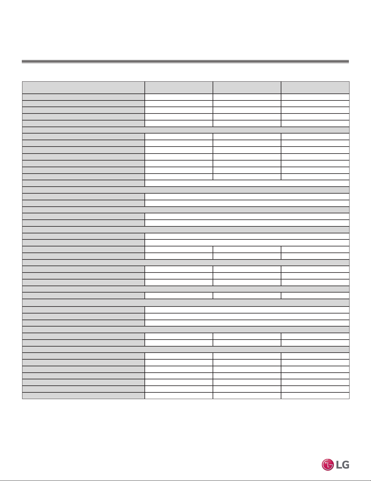
MECHANICAL SPECIFICATIONS
General
LG Single Zone Wall Mounted Extended
Piping systems are comprised of a single
outdoor unit connected to a single indoor
unit with a single refrigerant circuit.
These single zone systems can operate in
either cooling or heating mode. These
systems are capable of changing mode
within a maximum time of three (3) minutes
to ensure temperature can be properly
maintained.
LG components are manufactured in
a facility registered to ISO 9001 and
ISO 14001, which is a set of standards
applying to environmental protection
set by the International Organization for
Standardization (ISO). Wiring in these
units are in accordance with the National
Electrical Code (NEC).
Temperature Ranges
Outdoor Unit
Operating ranges for outdoor units of 14°F
to 118°F DB for cooling and -4°F to 65°F
WB for heating.
Indoor Unit
Operating ranges for indoor units of 53°F to
75°F WB for cooling and 60°F to 86°F DB
for heating.
Installing an optional Low Ambient Wind
Baffle Kit will allow operation down to 0°F in
cooling mode for all single zone systems.
Casing / Frame
Outdoor unit is constructed with pre-coated
metal (PCM).
Indoor unit is constructed of heavy duty
Acrylonitrile Butadiene Styrene (ABS) and
High Impact Polystyrene (HIPS) plastic.
Refrigerant System
The refrigeration system consists of a
single refrigeration circuit and uses R410A
refrigerant. The outdoor unit is provided with
factory installed components, including a
refrigerant strainer, four-way reversing valve,
electronic controlled expansion valve (EEV),
high and low side charging ports, service
valves, and interconnecting piping.
Refrigeration Oil Control
Heat pump outdoor units have a centrifugal
oil separator and controls to ensure sufficient
oil supply is maintained, and that oil does
not travel with the refrigerant.
Compressors
The outdoor unit is equipped with one
hermetic digitally controlled inverter driven
twin rotary compressor to modulate capacity
(modulation in 1 Hz increments).
Frequency ranges for the outdoor units are
as follows:
LSU243HLV3: 10 Hz ~ 70 Hz for Cooling;
10 Hz ~ 100 Hz for Heating.
LSU303HLV3: 10 Hz ~ 60 Hz for Cooling;
10 Hz ~ 90 Hz for Heating.
LSU363HLV3: 10 Hz ~ 64 Hz for Cooling;
10 Hz ~ 90 Hz for Heating.
Overcurrent protection and vibration isolation
are integrated with the compressor.
Outdoor Unit Coil
Heat pump outdoor unit coils are made of
a nonferrous construction with louvered
fins on copper tubing, and are protected
with an integral coil guard. Coil fins have a
factory applied corrosion resistant GoldFinTM
material with hydrophilic coating. Outdoor
units include factory-installed drain pan
heaters.
Fans and Motors
The outdoor unit includes one direct fan
drive, variable speed variable speed
propeller type fan.
The Brushless Digitally Controlled (BLDC)
fan motor included inherent protection,
permanently lubricated bearings, and
variable speed with a maximum speed up to
950 rpm. Raised guards are provided to limit
contact with moving parts.
The outdoor unit has horizontal discharge
airflow.
Electrical
These units are available in 208-230V, 60
Hz, 1-phase power supply. These units are
capable of operating within voltage limits of
± 10% rated voltage, and include
overcurrent protection.
Controls
The indoor unit casing has a factory-
standard, integral, infrared sensor designed
to communicate with the supplied LG
wireless handheld remote controller. An
optional LG supplied wired controller is
available as an additional accessory.
Communication between the indoor unit and
the outdoor unit is accomplished through 14
AWG four-core, stranded, shielded power /
communication cable.
HLV3 indoor units have built-in Wi-Fi and
can be controlled by LG’s Smart ThinQ™
app on a smartphone. A field-supplied Wi-Fi
network and smart device are required. The
Smart ThinQ app is free, and is available for
Android™ and iOS. (Android is a trademark
of Google LLC.)
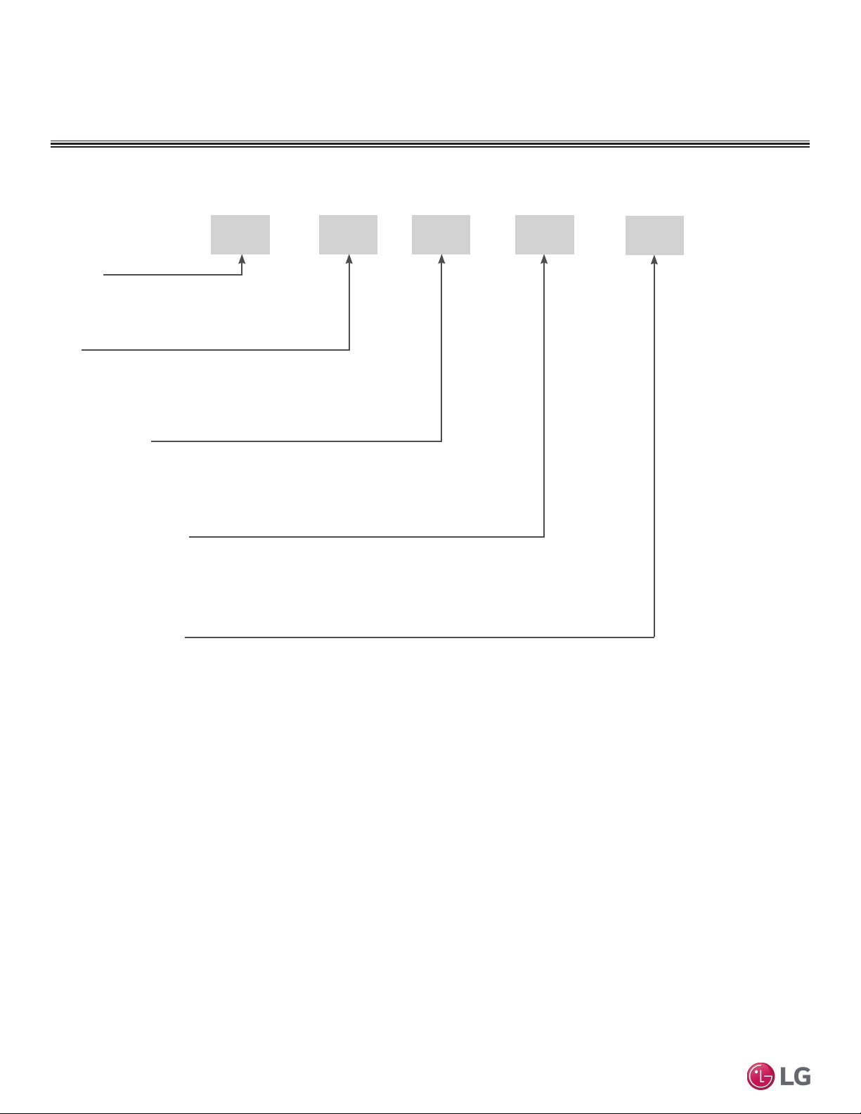
Figure 3: LS303HLV3 and LS363HLV3 Ex-
tended Piping Wall Mounted System.
Extended Piping Wall Mounted System

PRODUCT DATA | 9
Product Data
'XHWRRXUSROLF\RIFRQWLQXRXVSURGXFWLQQRYDWLRQVRPHVSHFL¿FDWLRQVPD\FKDQJHZLWKRXWQRWL¿FDWLRQ
© /*(OHFWURQLFV86$,QF(QJOHZRRG&OLIIV1-$OOULJKWVUHVHUYHG³/*´LVDUHJLVWHUHGWUDGHPDUNRI/*&RUS
GENERAL DATA
Extended Piping Wall Mounted System Pairing Table
The following tables show the available outdoor and indoor units, along with the factory provided controllers.
Table 1: Single Zone Wall Mounted Extended Piping System Pairing Table
Outdoor Unit Model Indoor Unit Model Controller
LSU243HLV3 LSN243HLV3 AKB74955602
LSU303HLV3
LSU363HLV3
LSN303HLV3
LSN363HLV3
AKB74955602

10 | PRODUCT DATA
Single Zone Extended Piping Wall Mounted Engineering Manual
'XHWRRXUSROLF\RIFRQWLQXRXVSURGXFWLQQRYDWLRQVRPHVSHFL¿FDWLRQVPD\FKDQJHZLWKRXWQRWL¿FDWLRQ
© /*(OHFWURQLFV86$,QF(QJOHZRRG&OLIIV1-$OOULJKWVUHVHUYHG³/*´LVDUHJLVWHUHGWUDGHPDUNRI/*&RUS
GENERAL DATA
([WHQGHG3LSLQJ:DOO0RXQWHG6\VWHP6SHFL¿FDWLRQV
Table 2: 6LQJOH=RQH([WHQGHG3LSLQJ:DOO0RXQWHG6SHFL¿FDWLRQV
System (Model) (Indoor Unit / Outdoor Unit) LS243HLV3
(LSN243HLV3/LSU243HLV3)
LS303HLV3
(LSN303HLV3/LSU303HLV3)
LS363HLV3
(LSN363HLV3/LSU363HLV3)
Cooling Capacity1(Min/Rated/Max) (Btu/h) 3,070 ~ 22,000 ~ 30,000 3,070 ~ 30,000 ~ 34,000 3,070 ~ 33,000 ~ 34,000
Cooling Power Input1(Rated) (kW) 1.69 2.66 3.30
Heating Capacity (Min/Rated/Max) (Btu/h) 3,070 ~ 26,000 ~ 36,200 3,070 ~ 32,400 ~ 38,900 3,070 ~ 35,200 ~ 38,900
Heating Power Input1(Rated) (kW) 2.08 2.75 3.12
COP 12.50 11.80 11.30
Maximum Heating Capacity (Btu/h)
Outdoor 17°F (WB)/Indoor 70°F (DB) 27,360 (105%) 32,500 (100%) 35,740 (102%)
Outdoor 5°F (WB)/Indoor 70°F (DB) 23,700 (91%) 28,080 (88%) 30,890 (88%)
Outdoor 0°F (WB)/Indoor 70°F (DB) 22,710 (87%) 26,180 (81%) 28,800 (82%)
Outdoor -4°F (WB)/Indoor 70°F (DB) 21,170 (81%) 24,390 (75%) 26,820 (76%)
EER 13.00 11.30 10.00
SEER 21.50 20.00 18.50
HSPF 12.00 11.50 11.00
Power Supply V, Ø, Hz2208-230/60/1
Outdoor Unit Operating Range3
Cooling (°F DB) 14 to 118
Heating (°F WB) -4 to +65
Indoor Unit Operating Range
Cooling (°F WB) 53 to 75
Heating (°F DB) 60 to 86
Unit Data
Refrigerant Type4R410A
Refrigerant Control EEV
IDU Sound Pressure Level dB(A) (Cooling) (H/M/L/SL)549 / 44 / 40 / 30 51 / 47 / 43 / 33 51 / 47 / 43 / 33
ODU Sound Pressure Level dB(Cooling/Heating) (A)555 / 56 55 / 58 55 / 58
Unit Weight (lbs.)
IDU (Net/Shipping) 36.6 / 44.5 40.8 / 48.9 40.8 / 48.9
ODU (Net/Shipping) 135.4 / 147.7 147.9 / 160.3 147.9 / 160.3
Power Wiring / Communications Cable (No. x AWG)64 x 14 4 x 14 4 x 14
Compressor
Compressor (Qty.) Twin Rotary (1) Twin Rotary (1) Twin Rotary (1)
Fan
IDU Type x Qty. Cross Flow Fan (1)
ODU Type x Qty. Propeller (1)
Motor / Drive Brushless Digitally Controlled / Direct
Airflow Rate
IDU (Cooling) (Max. / H / M / L [CFM]) 813 / 601 / 495 / 389 1,095 / 883 / 742 / 601 1,095 / 883 / 742 / 601
ODU (Max. [CFM]) 2,119 2,295 2,295
Piping
Liquid (in.) 3/8 Flare 3/8 Flare 3/8 Flare
Vapor (in.) 5/8 Flare 5/8 Flare 5/8 Flare
Condensate Drain O.D. / I.D. (in.) 25/32, 19/32 25/32, 19/32 25/32, 19/32
Additional Refrigerant Charge (oz./ft.) 0.38 0.38 0.38
Pipe Length7(Minimum / Maximum) (ft.) 9.8 / 164.0 9.8 / 164.0 9.8 / 164.0
Piping Length7(no add’l refrigerant, ft.) 24.6 24.6 24.6
Max. Elevation Difference (ft.) 98.4 98.4 98.4
EEV: Electronic Expansion Valve IDU: Indoor Unit ODU: Outdoor Unit
This unit comes with a dry helium charge.
This data is rated 0 ft above sea level with 24.6 of refrigerant line per indoor unit and a 0 ft level
difference outdoor and indoor units.
Cooling capacity rating obtained with air entering the indoor unit at 80ºF dry bulb (DB) and 67ºF wet
bulb (WB) and outdoor ambient conditions of 95ºF dry bulb (DB) and 75ºF wet bulb (WB).
Heating capacity rating obtained with air entering the indoor unit at 70ºF dry bulb (DB) and 59ºF wet
bulb (WB) and outdoor ambient conditions of 47ºF dry bulb (DB) and 43ºF wet bulb (WB).
1Power Input is rated at high speed.
2Power wiring to the ODU is field supplied, solid or stranded, and must comply with the applicable local
and national codes.
3Low Ambient Wind Baffle Kit (sold separately) allows operation down to 0°F in cooling mode.
4Take appropriate actions at the end of HVAC equipment life to recover, recycle, reclaim or destroy R410A
refrigerant according to applicable regulations (40 CFR Part 82, Subpart F) under section 608 of CAA.
5Sound pressure levels are tested in an anechoic chamber under ISO Standard 3745.
6All communication / connection (power) cable from the outdoor unit to the indoor unit is field supplied
and must be a minimum of four-conductor, 14 AWG, stranded, shielded or unshielded (if shielded, it
must be grounded to the chassis of the outdoor unit only), and must comply with applicable local and
national codes. For detailed electrical information, please refer to electric characteristics on page 11.
7Piping lengths are equivalent.

PRODUCT DATA | 11
Product Data
'XHWRRXUSROLF\RIFRQWLQXRXVSURGXFWLQQRYDWLRQVRPHVSHFL¿FDWLRQVPD\FKDQJHZLWKRXWQRWL¿FDWLRQ
© /*(OHFWURQLFV86$,QF(QJOHZRRG&OLIIV1-$OOULJKWVUHVHUYHG³/*´LVDUHJLVWHUHGWUDGHPDUNRI/*&RUS
ELECTRICAL DATA
Nominal
Tons
Unit Model
Number Hertz Voltage Voltage Range
(Min. to Max.) MCA MOP Compressor
Qty.
Compressor Motor
RLA
Outdoor Fan
Motor
Indoor Fan
Motor
Cooling Heating W FLA W FLA
2 LS243HLV3
60 208 - 230 187 - 253
19.0 30 1 14.41 14.41 124 0.4 58 0.5
2-1/2 LS303HLV3 23.0 30 1 15.1 15.1 124 0.25 110 0.5
2-3/4 LS363HLV3 23.0 30 1 15.1 15.1 124 0.25 110 0.5
Table 3: 208-230V, 60Hz, 1-Phase Single-Zone Extended Piping Wall-Mounted Electrical Data.
Voltage tolerance is ±10%.
Maximum allowable voltage unbalance is 2%.
MCA = Minimum Circuit Ampacity.
Maximum Overcurrent Protection (MOP) is calculated as follows: (Largest motor FLA x 2.25) + (Sum of
other motor FLA) rounded down to the nearest standard fuse size.
RLA = Rated Load Amps.
FLA = Full Load Amps.
Extended Piping Wall Mounted Systems

12 | PRODUCT DATA
Single Zone Extended Piping Wall Mounted Engineering Manual
'XHWRRXUSROLF\RIFRQWLQXRXVSURGXFWLQQRYDWLRQVRPHVSHFL¿FDWLRQVPD\FKDQJHZLWKRXWQRWL¿FDWLRQ
© /*(OHFWURQLFV86$,QF(QJOHZRRG&OLIIV1-$OOULJKWVUHVHUYHG³/*´LVDUHJLVWHUHGWUDGHPDUNRI/*&RUS
FUNCTIONS, CONTROLS, OPTIONS
Table 4: Indoor Units—Functions, Controls and Options.
Indoor Unit Type LS243HLV3 LS303HLV3 LS363HLV3
$LUÀRZ
Air Supply Outlet 111
Airflow Direction Control (Left / Right) 5 Steps 5 Steps 5 Steps
Airflow Direction Control (Up / Down) 6 Steps 6 Steps 6 Steps
Auto Swing (Left / Right) ¥¥¥
Auto Swing (Up / Down) ¥¥¥
Fan Speed Airflow Steps (Fan / Cool / Heat) 6 / 6 / 6 6 / 6 / 6 6 / 6 / 6
Natural Wind (Auto Wind) ¥¥¥
Jet Cool / Jet Heat (Power Wind) ¥¥ ¥¥ ¥¥
Comfort Air ¥¥¥
Air Purifying
Washable Anti-Bacteria Prefilter1¥¥¥
Deodorizing Filter XXX
Plasma XXX
Micro Dust Filter XXX
Allergy Filter XXX
Functions
Hot Start ¥¥¥
Self Diagnostics ¥¥¥
Defrost ¥¥¥
Dry (Dehumidification Operation) ¥¥¥
Auto Changeover ¥¥¥
Auto Cleaning (Coil Dry) ¥¥¥
Auto Restart ¥ ¥ ¥
Child Lock (Applicable with Wired Controller) ooo
Forced Operation ¥¥¥
Sleep Mode ¥+RXU ¥+RXU ¥+RXU
Timer 24 hour (On / Off) ¥¥¥
Weekly Timer (Applicable with Wired Controller) ooo
Two Thermistor Control ooo
Low Ambient ¥ ¥ ¥
Overheating Protection ¥¥¥
Low Heating ¥¥¥
Smart Diagnosis ¥¥¥
Indoor Display Type Number Display Number Display Number Display
Indoor Unit Display Light On / Off On / Off On / Off
Energy Saving ¥¥¥
Drain Pan Heater ¥¥¥
Controllers
Wireless Handheld Remote Controller ¥$.%
Programmable Controllers (MultiSITE CRC1 / CRC1+) o (PREMTBVC0 / PREMTBVC1)
Simple Remote Controller o (PREMTC00U)
Premium Remote Controller o (PREMTA000)
Dry Contact o (PDRYCB100 / 300 / 400)
Network Solution (LGAP) ooo
Central
Controllers /
Integration
Solutions
AC Smart 5 o (PACS5A000)
ACP 5 o (PACP5A000)
PI-485 o (PMNFP14A1)
MultiSITE Communications Manager o (PBACNBTR0A)
MultiSITE VM3 o (PBACNBTR1B)
Special
Functions
Wi-Fi Module (Built In) ¥¥¥
Water Level Sensor Connection (for Optional AG-9300-LG) ooo
Wind Baffle Kit o (ZLABGP04A)
Other
Mode Lock Cooling Only or Heating Only
Temperature Control Thermistor
Smart Inverter Monitoring System (SIMs) o (PSWMOZ3)
1Primary washable filters. ¥ 6WDQGDUGIHDWXUH
o = Optional accessory (must be purchased separately)
X = Not available
• When Dry Contact Mode active, Wi-Fi Function can not be used.
• When changing from Wi-Fi mode to dry contact mode, normal operation resumes in approximately 3 minutes.

PRODUCT DATA | 13
Product Data
'XHWRRXUSROLF\RIFRQWLQXRXVSURGXFWLQQRYDWLRQVRPHVSHFL¿FDWLRQVPD\FKDQJHZLWKRXWQRWL¿FDWLRQ
© /*(OHFWURQLFV86$,QF(QJOHZRRG&OLIIV1-$OOULJKWVUHVHUYHG³/*´LVDUHJLVWHUHGWUDGHPDUNRI/*&RUS
OUTDOOR UNIT DIMENSIONS
LSU243HLV3, LSU303HLV3, LSU363HLV3
Unit : Inch (mm)
Drain Hole 5-Ø13/16 (20)
6-17/32 (166)
15-7/16 (392)
1-1/32 (26)
13 (330)
1-9/16 (40)
Ø22-1/8 (562)
2-17/32 (64)
32-3/4 (832)
5-13/16 (148)
3-9/32 (83)
5-9/16 (141)
15/16 (24)
13-7/32 (336)
24-13/32 (620)
14-3/16 (360)
15-11/32 (390)
25° 14°14°
3-5/32 (80)
Vapor Pipe Conn.
(Flare Joint)
Service Valve Cover
Power / Comm.
Cable Holes
Control
Box
Air Outlet
Drain Hole 5-Ø13/16 (20)
6-17/32 (166)
15-7/16 (392)
1-1/32 (26)
37-13/32 (950) 13 (330)
1-9/16 (40)
Ø22-1/8 (562)
2-17/32 (64)
32-3/4 (832)
5-13/16 (148)
3-9/32 (83)
5-9/16 (141)
15/16 (24)
13-7/32 (336)
24-13/32 (620)
14-3/16 (360)
15-11/32 (390)
25° 14°14°
3-5/32 (80)
Liquid Pipe Conn.
(Flare Joint)
Sump Heater

14 | PRODUCT DATA
Single Zone Extended Piping Wall Mounted Engineering Manual
'XHWRRXUSROLF\RIFRQWLQXRXVSURGXFWLQQRYDWLRQVRPHVSHFL¿FDWLRQVPD\FKDQJHZLWKRXWQRWL¿FDWLRQ
© /*(OHFWURQLFV86$,QF(QJOHZRRG&OLIIV1-$OOULJKWVUHVHUYHG³/*´LVDUHJLVWHUHGWUDGHPDUNRI/*&RUS
d
e
a
b
c
AD
BC
Figure 4: Center of Gravity and Corner Weight Dimensions Diagram.
OUTDOOR UNIT CENTER OF GRAVITY /
CORNER WEIGHT
Model Weight (lb.) Center of Gravity (inch) Leg (inch) Corner Weight (lb.)
Shipping Net a b c d e A B C D
LSU243HLV3 147.7 135.4 23-7/32 12-19/32 5-29/32 24-13/32 14-3/16 18.6 24.2 49.1 43.5
LSU303HLV3, LSU363HLV3 160.3 147.9 23-7/32 12-19/32 5-29/32 24-13/32 14-3/16 20.3 26.5 53.7 47.4
Table 5: Center of Gravity and Corner Weight Dimensions.

PRODUCT DATA | 15
Product Data
'XHWRRXUSROLF\RIFRQWLQXRXVSURGXFWLQQRYDWLRQVRPHVSHFL¿FDWLRQVPD\FKDQJHZLWKRXWQRWL¿FDWLRQ
© /*(OHFWURQLFV86$,QF(QJOHZRRG&OLIIV1-$OOULJKWVUHVHUYHG³/*´LVDUHJLVWHUHGWUDGHPDUNRI/*&RUS
INDOOR UNIT DIMENSIONS
LSN243HLV3
Unit: Inch (mm)
Decoration Cover Drain Hose
Connection
* If airflow direction control is available,
Cooling
Installation Plate
Heating
Up & Down Left & Right
[8-5/8 (219)]
Air Intake Hole
Left
45°
12°
22°
57°
47°
45°
2-5/8 (67)
7/16 (11)
15/32 (12)
2-3/8 (60)
41-23/32 (1060)
14-3/16 (360)
14-23/32 (374)
[2-23/32 (69)]
Air Outlet Hole
[37-9/16 (954)]
Air Intake Hole
Rear Rear
Right
[35-13/32 (899)]
Air Intake Hole
Bottom
2-1/16 (52)
3-15/16 (100)
41-23/32 (1060)
Approx. 11-25/32 (299) to liquid pipe
Approx. 14-1/8 (359) to gas pipe
In Case of Left Side Piping
Unit Outline
Connecting Gas/Liquid Pipe
14-23/32 (374)
2-5/32 (55)
4-21/32 (118)
1-17/32 (47)
2-3/8 (60)
2-15/32 (63)
1-3/32 (50.2) 1-1/16 (26.2)
2-7/16 (61.5)
1-7/16(33.5)
1/4(6) x 1/8(3)
1/8(3) x 1/4(6)
5/8(15.3) 1-9/32(32.7)
5-31/32 (152)
1-1/4 (31)
2-13/32(61)
41-23/32 (1060)
14-29/32 (379) 7-27/32 (199)
8-7/16 (214)
6-5/16 (160)
2 (51)
9-1/32 (229)
Ø2-9/16 (65)
2-3/4 (70)
14-23/32 (374)
2-3/4 (70)
2-3/4 (70)
12-1/8 (308)
2 (51)
4-11/32 (110)
3-3/8 (86)
5-25/32 (147)
Ø2-9/16 (65)
Unit Bottom Line
Unit Outline
Fixing the Installation Plate, Drilling Hole
10-7/16 (265)
2-3/8 (60)
15/32 (12)
2-5/8 (67)
7/16 (11)
Air Intake
Air Outlet
5-3/16 (132)
5-3/16 (132)
2-3/4 (70)
Refrigerant,
Drain Pipe
and Cable
Routing Hole
Refrigerant,
Drain Pipe and
Cable Routing
Hole
Display / Remote Controller
Signal Receiver
Refrigerant,
Drain Pipe and
Cable Routing Hole
Terminal Block for
Power Supply and
Communication

16 | PRODUCT DATA
Single Zone Extended Piping Wall Mounted Engineering Manual
'XHWRRXUSROLF\RIFRQWLQXRXVSURGXFWLQQRYDWLRQVRPHVSHFL¿FDWLRQVPD\FKDQJHZLWKRXWQRWL¿FDWLRQ
© /*(OHFWURQLFV86$,QF(QJOHZRRG&OLIIV1-$OOULJKWVUHVHUYHG³/*´LVDUHJLVWHUHGWUDGHPDUNRI/*&RUS
INDOOR UNIT DIMENSIONS
LSN303HLV3, LSN363HLV3
Unit: Inch (mm)
47-1/4 (1200)
2-3/4 (70)
14-29/32 (379) 8 (203)
8-19/32 (218)
6-13/32 (163)
2 (51)
9-3/16 (233)
14-23/32 (374)
Ø2-9/16 (65)
9-11/16 (246)
10-9/16 (68)
12-1/8 (308)
2-3/4 (70)
Ø2-9/16 (65)
8-5/8 (219)
2 (51)
11-5/32 (283)
Decoration Cover
Display / Remote
Controller Signal
Receiver
Terminal Block
for Power
Supply and
Communication
Drain Hose Connection
* If airflow direction control is available,
Cooling
Installation Plate
Heating
Up & Down Left & Right
[8-5/8 (219)]
Air Intake Hole
Left
45°
12°
22°
57°
47°
45°
2-3/8 (60)
15/32 (12)
7/16 (11)
2-5/8 (67)
47-1/4 (1200)
14-3/16 (360)
14-23/32 (374)
[2-23/32 (69)]
Air Outlet Hole
[43-3/16 (1097)]
Air Intake Hole
Rear Rear
Right
10-7/16 (265)
2-5/8 (67)
7/16 (11)
15/32 (12)
2-3/8 (60)
Air Intake
Air Outlet
47-1/4 (1200)
Approx. 17-1/8 (435) to liquid pipe
Approx.19-1/2 (495) to gas pipe
In Case of Left Side Piping
Unit Outline
Connecting Gas/Liquid Pipe
14-23/32 (374)
2-5/32 (55)
4-27/32 (123)
2-3/8 (60)
2-9/32 (58)
4-1/16 (103)
1-31/32 (50)
[40-19/32 (1031)]
Air Intake Hole Bottom
Unit Bottom Line
Unit Outline
Fixing the Installation Plate, Drilling Hole
66
2-19/32 (66)
1-3/32 (50.2) 1-1/16 (26.2)
2-7/16 (61.5)
1-7/16(33.5)
1/4(6) x 1/8(3)
1/8(3) x 1/4(6)
5/8(15.3) 1-9/32(32.7)
5-31/32 (152)
1-1/4 (31)
2-13/32(61)
Refrigerant,
Drain Pipe
and Cable
Routing Hole
Refrigerant,
Drain Pipe
and Cable
Routing Hole
Refrigerant,
Drain Pipe
and Cable
Routing Hole

PRODUCT DATA | 17
Product Data
'XHWRRXUSROLF\RIFRQWLQXRXVSURGXFWLQQRYDWLRQVRPHVSHFL¿FDWLRQVPD\FKDQJHZLWKRXWQRWL¿FDWLRQ
© /*(OHFWURQLFV86$,QF(QJOHZRRG&OLIIV1-$OOULJKWVUHVHUYHG³/*´LVDUHJLVWHUHGWUDGHPDUNRI/*&RUS
INDOOR UNIT ACOUSTIC DATA
Figure 5: Extended Piping Wall Mounted
Indoor Unit Sound Level Measurement
Location.
2.6 feet
(0.8 m)
3.3 feet (1 m)
Microphone
Model Cooling Heating
HMLHML
LSN243HLV3 49 44 40 49 44 40
LSN303HLV3 51 47 43 51 47 43
LSN363HLV3 51 47 43 51 47 43
Table 6: Extended Piping Wall Mounted Indoor Unit Sound Pressure Data.
• Measurements are taken 3.3 feet (1 m) away from the front of the unit.
• Sound pressure levels are measured in dB(A) with a tolerance of ±1.
• Reference acoustic pressure 0dB=20μPa.
• Data is valid at nominal operation conditions. Operating conditions are assumed to be standard.
• Sound pressure levels are tested in an anechoic chamber under ISO Standard 3745, and may
be different according to the test condition or equipment.
• Sound level will vary depending on a range of factors including the construction (acoustic ab-
sorption coefficient) of a particular room in which the unit was installed.
LSN243HLV3
Cooling Heating
Octave Band Sound Pressure Level
G% ȝ3D
Octave Band Center Frequency (Hz
10
20
30
40
50
60
70
80
63 125 250 500 1000 2000 4000 8000
ŶHigh
ƔLow
ŸMiddle
NC-15
NC-20
NC-25
NC-30
NC-35
NC-40
NC-45
NC-50
NC-55
NC-60
NC-65
Approximate
Hearing
Threshold
Octave Band Sound Pressure Level
G% ȝ3D
Octave Band Center Frequency (Hz
10
20
30
40
50
60
70
80
63 125 250 500 1000 2000 4000 8000
ŶHigh
ƔLow
ŸMiddle
NC-15
NC-20
NC-25
NC-30
NC-35
NC-40
NC-45
NC-50
NC-55
NC-60
NC-65
Approximate
Hearing
Threshold
Figure 6: Sound Pressure Levels for LSN243HLV3 Indoor Units.
Indoor Unit Sound Pressure Measurement / Sound Pressure Levels
LSN243HLV3 Sound Pressure Levels
Extended Piping Wall Mounted Systems

18 | PRODUCT DATA
Single Zone Extended Piping Wall Mounted Engineering Manual
'XHWRRXUSROLF\RIFRQWLQXRXVSURGXFWLQQRYDWLRQVRPHVSHFL¿FDWLRQVPD\FKDQJHZLWKRXWQRWL¿FDWLRQ
© /*(OHFWURQLFV86$,QF(QJOHZRRG&OLIIV1-$OOULJKWVUHVHUYHG³/*´LVDUHJLVWHUHGWUDGHPDUNRI/*&RUS
Figure 7: Sound Pressure Levels for LSN303HLV3 Indoor Units.
INDOOR UNIT ACOUSTIC DATA
LSN363HLV3
gnitaeHgnilooC
10
20
30
40
50
60
70
80
63 125 250 500 1000 2000 4000 8000
ŶHigh
ƔLow
ŸMiddle
NC-15
NC-20
NC-25
NC-30
NC-35
NC-40
NC-45
NC-50
NC-55
NC-60
NC-65
Approximate
Hearing
Threshold
Octave Band Sound Pressure LevelG% ȝ3D
Octave Band Center Frequency (Hz
10
20
30
40
50
60
70
80
63 125 250 500 1000 2000 4000 8000
ŶHigh
ƔLow
ŸMiddle
NC-15
NC-20
NC-25
NC-30
NC-35
NC-40
NC-45
NC-50
NC-55
NC-60
NC-65
Approximate
Hearing
Threshold
Octave Band Sound Pressure LevelG% ȝ3D
Octave Band Center Frequency (Hz
LSN303HLV3
gnitaeHgnilooC
10
20
30
40
50
60
70
80
63 125 250 500 1000 2000 4000 8000
ŶHigh
ƔLow
ŸMiddle
NC-15
NC-20
NC-25
NC-30
NC-35
NC-40
NC-45
NC-50
NC-55
NC-60
NC-65
Approximate
Hearing
Threshold
Octave Band Sound Pressure Level
G% ȝ3D
Octave Band Center Frequency (Hz
10
20
30
40
50
60
70
80
63 125 250 500 1000 2000 4000 8000
ŶHigh
ƔLow
ŸMiddle
NC-15
NC-20
NC-25
NC-30
NC-35
NC-40
NC-45
NC-50
NC-55
NC-60
NC-65
Approximate
Hearing
Threshold
Octave Band Sound Pressure Level
G% ȝ3D
Octave Band Center Frequency (Hz
LSN303HLV3 and LSN363HLV3 Sound Pressure Levels
Extended Piping Wall Mounted Systems
Figure 8: Sound Pressure Levels for LSN363HLV3 Indoor Units.

PRODUCT DATA | 19
Product Data
'XHWRRXUSROLF\RIFRQWLQXRXVSURGXFWLQQRYDWLRQVRPHVSHFL¿FDWLRQVPD\FKDQJHZLWKRXWQRWL¿FDWLRQ
© /*(OHFWURQLFV86$,QF(QJOHZRRG&OLIIV1-$OOULJKWVUHVHUYHG³/*´LVDUHJLVWHUHGWUDGHPDUNRI/*&RUS
OUTDOOR UNIT ACOUSTIC DATA
Model Cooling Heating
HH
LSU243HLV3 55 56
LSU303HLV3 55 58
LSU363HLV3 55 58
Table 7: Extended Piping Wall Mounted Outdoor Unit Sound Pressure Data.
Figure 9: Extended Piping Wall Mounted Outdoor Unit Sound Level
Measurement Location.
3.3 feet (1 m)
Center of
Outdoor Unit
Figure 10: Sound Pressure Levels for LSU243HLV3 Outdoor Units.
• Measurements are taken 3.3 feet (1 m) away from the front of the
unit.
• Sound pressure levels are measured in dB(A) with a tolerance of
±1.
• Data is valid at nominal operation conditions. Operating conditions
are assumed to be standard.
• Reference acoustic pressure 0dB=20μPa.
• Sound pressure levels are tested in an anechoic chamber under
ISO Standard 3745, and may be different according to the test
condition or equipment.
• Sound level will vary depending on a range of factors including the
construction (acoustic absorption coefficient) of a particular room in
which the unit was installed.
LSU243HLV3
Cooling Heating
Octave Band Sound Pressure LevelG% ȝ3D
Octave Band Center Frequency (Hz
10
20
30
40
50
60
70
80
63 125 250 500 1000 2000 4000 8000
Front
Back
NC-15
NC-20
NC-25
NC-30
NC-35
NC-40
NC-45
NC-50
NC-55
NC-60
NC-65
Approximate
Hearing
Threshold
Octave Band Sound Pressure LevelG% ȝ3D
Octave Band Center Frequency (Hz
10
20
30
40
50
60
70
80
63 125 250 500 1000 2000 4000 8000
Front
Back
NC-15
NC-20
NC-25
NC-30
NC-35
NC-40
NC-45
NC-50
NC-55
NC-60
NC-65
Approximate
Hearing
Threshold
Outdoor Unit Sound Pressure Measurement / Sound Pressure Levels
LSU243HLV3 Sound Pressure Levels
Extended Piping Wall Mounted Systems

20 | PRODUCT DATA
Single Zone Extended Piping Wall Mounted Engineering Manual
'XHWRRXUSROLF\RIFRQWLQXRXVSURGXFWLQQRYDWLRQVRPHVSHFL¿FDWLRQVPD\FKDQJHZLWKRXWQRWL¿FDWLRQ
© /*(OHFWURQLFV86$,QF(QJOHZRRG&OLIIV1-$OOULJKWVUHVHUYHG³/*´LVDUHJLVWHUHGWUDGHPDUNRI/*&RUS
LSU303HLV3
Cooling Heating
10
20
30
40
50
60
70
80
63 125 250 500 1000 2000 4000 8000
Ɣ
ŸFront
Back
NC-15
NC-20
NC-25
NC-30
NC-35
NC-40
NC-45
NC-50
NC-55
NC-60
NC-65
Approximate
Hearing
Threshold
Octave Band Sound Pressure LevelG% ȝ3D
Octave Band Center Frequency (Hz
10
20
30
40
50
60
70
80
63 125 250 500 1000 2000 4000 8000
Front
Back
NC-15
NC-20
NC-25
NC-30
NC-35
NC-40
NC-45
NC-50
NC-55
NC-60
NC-65
Approximate
Hearing
Threshold
Octave Band Sound Pressure LevelG% ȝ3D
Octave Band Center Frequency (Hz
LSU363HLV3
Cooling Heating
10
20
30
40
50
60
70
80
63 125 250 500 1000 2000 4000 8000
Ɣ
ŸFront
Back
NC-15
NC-20
NC-25
NC-30
NC-35
NC-40
NC-45
NC-50
NC-55
NC-60
NC-65
Approximate
Hearing
Threshold
Octave Band Sound Pressure LevelG% ȝ3D
Octave Band Center Frequency (Hz
10
20
30
40
50
60
70
80
63 125 250 500 1000 2000 4000 8000
Front
Back
NC-15
NC-20
NC-25
NC-30
NC-35
NC-40
NC-45
NC-50
NC-55
NC-60
NC-65
Approximate
Hearing
Threshold
Octave Band Sound Pressure LevelG% ȝ3D
Octave Band Center Frequency (Hz
Figure 11: Sound Pressure Levels for LSU303HLV3 Outdoor Units.
OUTDOOR UNIT ACOUSTIC DATA
Extended Piping Wall Mounted Systems
LSU303HLV3 and LSU363HLV3 Sound Pressure Levels
Figure 12: Sound Pressure Levels for LSU363HLV3 Outdoor Units.
Other manuals for LS243HLV3
1
This manual suits for next models
2
Table of contents
Other LG Air Conditioner manuals
Popular Air Conditioner manuals by other brands

mundoclima
mundoclima CL23390 Installaton manual

York
York F2FP040H06 User's information manual

Maplin
Maplin A75TB user manual

Fujitsu
Fujitsu AUT12 operating manual

Olimpia splendid
Olimpia splendid maeStro Pro Instructions for installation, use and maintenance

Soleus Air
Soleus Air GB-PAC-08E4 operating instructions