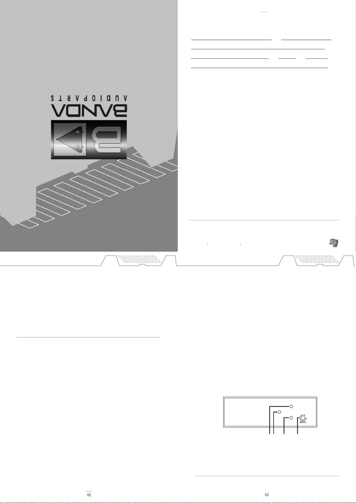
CLIP INDICATOR
Power supply section
1. Negative power input (ground): connect to car chassis.
2. Protection fuse: • .
3. Remote input: connect to radio/cd remote output.
4. Positive power input (+12Vdc): connect to baterry positive terminal.
234
1
Crossover Control
Sets the beggining of response Sets the end of response
Subsonic Control
Signal input and power output section.
1. Positive speaker output
2. Signal input (RCA)
3. Subsonic control
4. Crossover control
5. Negative speaker output
1 2 3 4 5
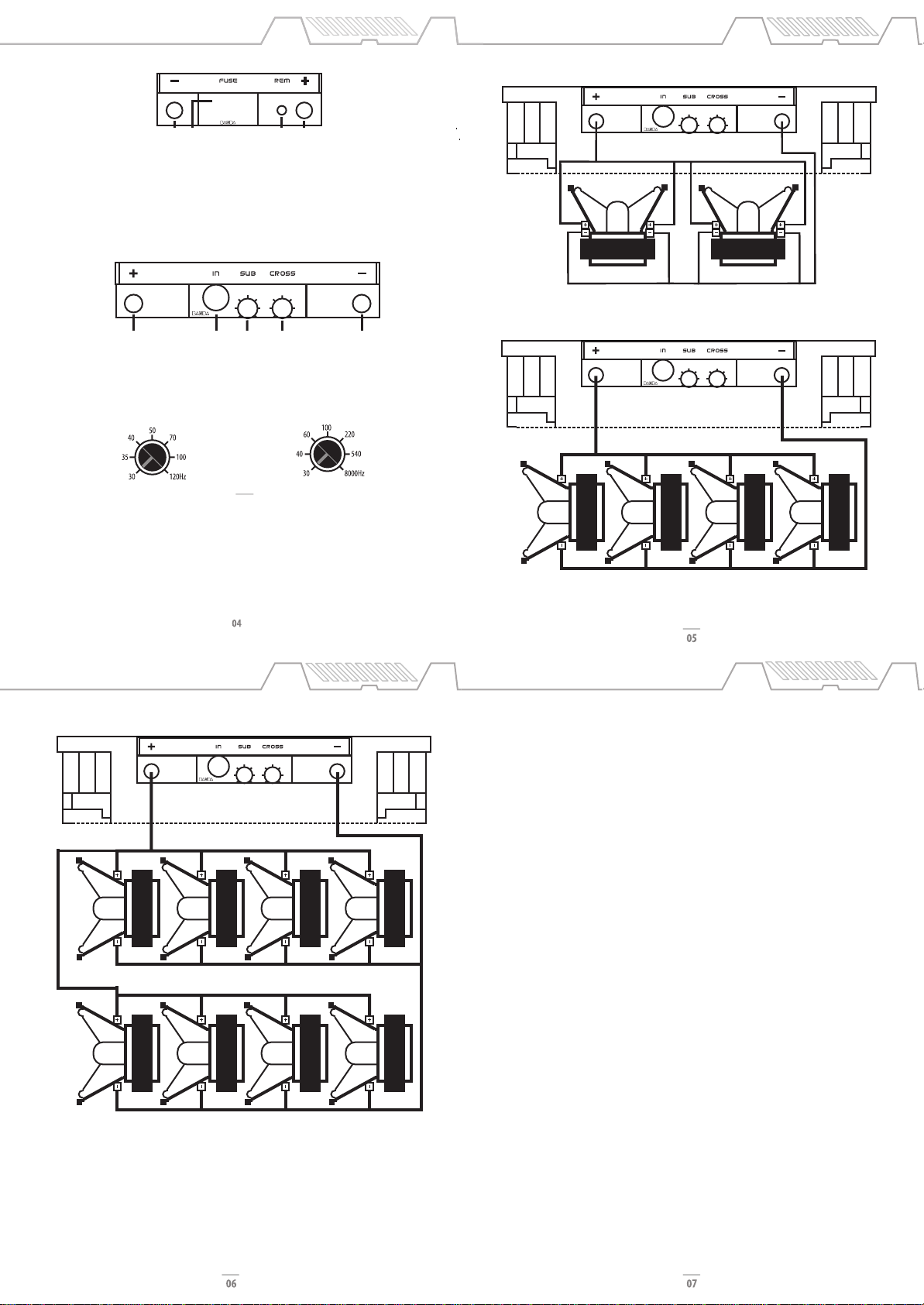
TECHNICAL SPECIFICATION CONNECTION EXAMPLES
CONNECTION EXAMPLE ICE 4002
The red LED lights up when the amplifier output is distorting. As long as the speakers used are capable of
handle the total output power this LED can eventually blink but if it holds still it means too much distortion in
the output and this can damage the speakers and the amplifier. In this case, turn down the head unit volume.
NOTE: These are basic projects, just given as examples.
NOTE: These are basic projects, just given as examples.
8 ohms 1250Wrms woofer x 8 wired in parallel
Short Circuit protection:
If short circuit is detected in output terminals, the amplifier shuts down an the red LED lights up. The equipment
must be turned off, solve the short circuit problem and turn the equipment on again. If the problem is solved,
the blue LED must light up. If the load impedance is lower than the amplifier specification, the equipment may
trigger the short circuit protection.
Low Voltage Protection:
When battery voltage is lower than 9Vdc, the amplifier will shut down and the yellow LED will blink until the
equipment is restarted.
Power Supply Inverted Cable Protection:
If the power supply cables are connected inverted, the internal fuse will blow.
Troubleshooting:
Protection triggered
1. Check if the internal fuse is blown. If so, replace it with a same current rate fuse (60A x 6)
2. Check if there is short circuit in the output terminals. To do it, turn off the amplifier, disconnect all speakers
and the input RCA cable and wait about 20 seconds. Turn the amplifier again and if the blue LED lights up, the
amplifier is operating normally.
3. Check if any speaker is presenting short circuit or the total impedance load is lower than the amplifier
specification.
4. Check if there is enough current in battery to supply the amplifier and if the cables are capable of conduct that
current.
Output Noise
1. Check if there is loose connection in signal input or in the RCA cable.
2. Check if there is ground connection in the radio/cd RCA output.
3. Check if RCA cables are wired separated from the power cables.
4. Check if the +12Vdc that powers the amplifier is coming directly from the battery.
5. Check if ground cable is connected in car chassis as near as possible of the amplifier.
6. Both radio/cd and amplifier must be firmly connected to car chassis ground to avoid noises and voltage
fluctuations at amplifier output.
Important Notes:
• Use 2 AWG power cables for both GND and +12Vdc.
• Do not use impedance load lower than the amplifier specification. This can damage the equipment.
• Use wire solder for tinning the cable end for better electrical contact. Loose electrical connection can cause
malfunction, heating and even fire
• The GND connection must be as short as possible, using adequate wire terminal firmly connected to a clean, paint
free spot at the car chassis.
• If more than one amplifier is used, provide adequate individual wiring for each one.
PROTECTION SYSTEM AND
TROUBLESHOOTING
4ohms 2500Wrms woofer x 84wired in parallel
4+4ohms 5000Wrms subwoofer x 2 wired in parallel