Banda Audioparts VIKING 15.000 User manual

CEP: 13148-1
15
Output:
1 channel 15.000Wrms 1ohm - 12.6Vdc
1 channel 9.800Wrms 2ohms - 12.6Vdc
1 channel 19.000Wrms 1ohm - 14.4Vdc
Current draw at full power(average music program): 630A*
*Equivalant to current draw with resistive load and sinusoidal signal at half power.
TECHNICAL SPECIFICATION
VIKING 15.000
02 .......... Technical Specification
03 .......... Technical Specification, front Panel and active filter
Power Supply, Signal Input and Power Output Sections04 ..........
Clip Indicator04 ..........
Subsonic and Crossover Controls 04 ..........
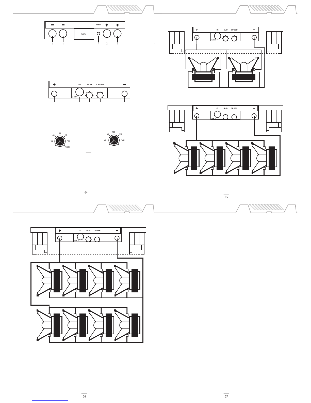
05 ..........Connetion Example
06 ..........Connection Example
07 .......... Protection System and Troubleshooting
08 .......... Warranty
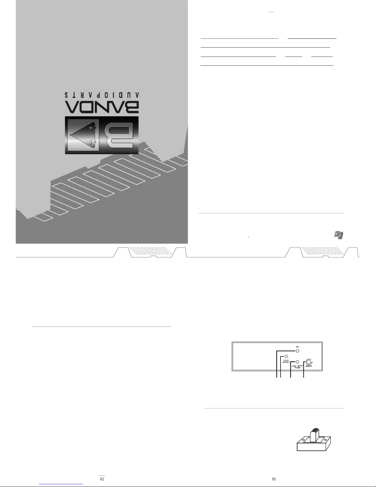
Front panel view
2 3 41
• Operation topology: Class D
• 12db/octave variable active Linkwitz-Riley crossover: 13Hz - 2kHz
• Frequency response: 13Hz - 2kHz (filter ON)
Frequency response: 13Hz - 3kHz (filter OFF)•
• Variable subsonic filter: 13Hz - 120Hz (filter ON)
• Fuse: MIDIVAL 125A (x 6) + 60A (x 1)
• Clip indicator
• THD < 0.5%
• SNR > 82dB
• Damping factor > 10
• Input sensitivity: 160mVRMS – 6VRMS
• Differential input signal impedance: 17kOhms
• Cooling fans
• Idle Current: 5.3A
• Dimensions: 29.6”L x 2.5”H x 10.1”W
• Weight: 29.8lb
These values are typical and may present some minor variation.
TECHNICAL SPECIFICATION
1. • Blue LED: On
2. • Red LED: Blinking - Output distorted (Clip) / Constant - Output short circuit
3. • Yellow LED: Fblinking - Low voltage battery / Constant - Fuse blown or missing)
4. Gain Control
www.bandaaudioparts.com
Made in Brazil
COSTUMER SERVICE:
55 (19) 3844-7173 - (19) 3844-7465 - (19) 3844-4923 •
BANDA@BANDAAUDIOPARTS.COM
WARRANTY
Banda Audioparts warrants this equipment to be free of all defects in material and workmanship for
a period of 12 months from the date of purchase
Within the period of this warranty, Banda Audioparts will repair or replace, free of charge, any part
proving defective in material or workmanship.
Warranty Exclusions:
1. Damage resulting from misuse, abuse, accident, alterations or improper installation;
2. Damage resulting from installation in surfaces subjected to high levels of vibration;
3. Corrective work necessitated by repairs made by anyone other than a Banda Audioparts
authorized service technician;
This warranty does not cover shipping costs.
The defective equipment must be shipped to the factory or to an authorized service center
Rua Manoel Joaquim Filho, 353 - Jd. Santa Terezinha II - Paulínia - SP - Brazil -
Banda Audioparts reserves the right to change the product and its specifications at any time
without prior notice.
Note:Permanent Technical Support
After the warranty expires, Banda Audioparts will continue to provide extensive technical
assistance directly or through its network of authorized service, charging, however, the repair
services and replacement of components
Warning: Continuous expose to sound pressure levels over 85dB may cause permenent hearing loss.
REGISTRATION DATA
Name:
Invoice: Date: Phone:
Address:
Shop: Phone:
08
USER MANUAL
INDEX
Linkwitz-Riley filter activeted by switch
Switch ON: Filter enable (Linkwitz-Riley 12dB/8ª)
Switch OFF: Filter desable ON OFF
OBS.: To access the filter switch remove the plastic cover under the amplifier.
The factory default filter position is ON.

13 13
CLIP INDICATOR
Power supply section
1. Negative power input (ground): connect to car chassis.
2. Positive power input (+12Vdc): connect to baterry positive terminal.
3. Remote input: connect to radio/cd remote output.
Crossover Control
Sets the beggining of response Sets the end of response
Subsonic Control
Signal input and power output section.
1. Positive speaker output
2. Signal input (RCA)
3. Subsonic control
4. Crossover control
5. Negative speaker output
1 2 3 4 5
TECHNICAL SPECIFICATION CONNECTION EXAMPLES
CONNECTION EXAMPLE
The red LED lights up when the amplifier output is showing more than 5% THD. As long as the speakers used are
capable of handle the total output power this LED can eventually blink but if it holds still it means too much
distortion in the output and this can damage the speakers and the amplifier. In this case, turn down the head unit
volume.
NOTE: These are basic projects, just given as examples.
8 ohms 1875Wrms woofer x 8 wired in parallel
Short Circuit protection:
If short circuit is detected in output terminals, the amplifier shuts down an the red LED lights up. The equipment
must be turned off, solve the short circuit problem and turn the equipment on again. If the problem is solved,
the blue LED must light up. If the load impedance is lower than the amplifier specification, the equipment may
trigger the short circuit protection.
Low Voltage Protection:
When battery voltage is lower than 9Vdc, the amplifier will shut down and the yellow LED will blink until the
equipment is restarted.
Power Supply Inverted Cable Protection:
If the power supply cables are connected inverted, the internal fuse will blow.
Troubleshooting:
Protection triggered
1. Check if the internal fuse is blown. If so, replace it with a same current rate fuse (125A x 6)
2. Check if there is short circuit in the output terminals. To do it, turn off the amplifier, disconnect all speakers
and the input RCA cable and wait about 20 seconds. Turn the amplifier again and if the blue LED lights up, the
amplifier is operating normally.
3. Check if any speaker is presenting short circuit or the total impedance load is lower than the amplifier
specification.
4. Check if there is enough current in battery to supply the amplifier and if the cables are capable of conduct that
current.
Output Noise
1. Check if there is loose connection in signal input or in the RCA cable.
2. Check if there is ground connection in the radio/cd RCA output.
3. Check if RCA cables are wired separated from the power cables.
4. Check if the +12Vdc that powers the amplifier is coming directly from the battery.
5. Check if ground cable is connected in car chassis as near as possible of the amplifier.
6. Both radio/cd and amplifier must be firmly connected to car chassis ground to avoid noises and voltage
fluctuations at amplifier output.
Important Notes:
• Use 2 x 0 AWG power cables for both GND and +12Vdc.
• Do not use impedance load lower than the amplifier specification. This can damage the equipment.
• Use wire solder for tinning the cable end for better electrical contact. Loose electrical connection can cause
malfunction, heating and even fire
• The GND connection must be as short as possible, using adequate wire terminal firmly connected to a clean, paint
free spot at the car chassis.
PROTECTION SYSTEM AND
TROUBLESHOOTING
4ohms 3750Wrms woofer x 4 wired in parallel
4+4ohms 7500Wrms subwoofer x 2 wired in parallel
2000Hz
Table of contents
Other Banda Audioparts Car Amplifier manuals