banks Monster User manual

Banks Monster®
Exhaust System
2008 Ford 6.8L (V-10) &
2011 Ford 6.2L (V-8) Crew Cab Short (6.75ft) Bed
F-250/F-350 Super Duty
THIS MANUAL IS FOR USE WITH MONSTER EXHAUST SYSTEMS 48725
Owner’sManual
with Installation Instructions

296524 v.3.0
General Installation
Practices
1. Before starting work, familiarize
yourself with the installation procedure
by reading all of the instructions.
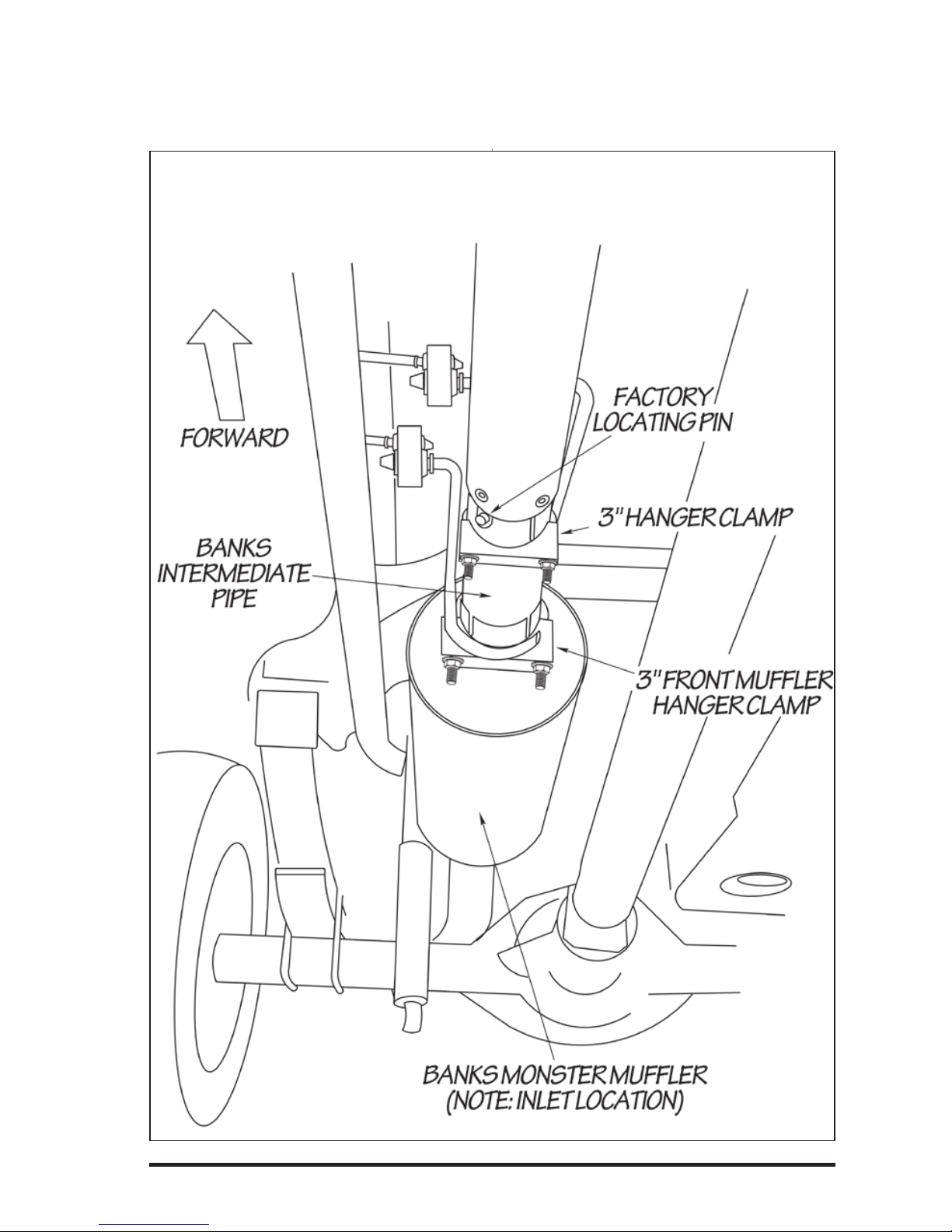
2. The exploded view (Figure 1)
provides only general guidance. Refer
to each step and section diagram in
this manual for proper instruction.
3. Throughout this manual, the
left side of the vehicle refers to the
driver’s side, and the right side to the
passenger’s side.
4. Disconnect the negative (ground)
cable from the battery (or batteries, if
there are two) before beginning work.
5. Route and tie wires and hoses a
minimum of 6” away from exhaust
heat, moving parts and sharp
edges. Clearance of 8” or more is
recommended where possible.
6. When raising the vehicle, support
it on properly weight-rated safety
stands, ramps or a commercial hoist.
Follow the manufacturer’s safety
precautions. Take care to balance the
vehicle to prevent it from slipping or
falling. When using ramps, be sure the
front wheels are centered squarely
on the topsides; put the transmission
in park; set the hand brake; and
place blocks behind the rear wheels.
Caution! Do not use floor jacks to
support the vehicle while working
under it. Do not raise the vehicle
onto concrete blocks, masonry
or any other item not intended
specifically for this use.
7. During installation, keep the work
area clean. Do not allow anything to
be dropped into intake, exhaust, or
lubrication system components while
performing the installation, as foreign
objects will cause immediate engine
damage upon start-up.
Tools Required:
• 1⁄2” and 3⁄8” drive ratchets with
standard and metric sockets and 1⁄2”
and 3⁄8” drive extension
• Standard and metric combination or
open-end wrenches
• Standard screwdriver
• Clean shop towels or rags
• Pry-bar
Highly recommended
tools and supplies:
• Foot-pound torque wrench
• Penetrating oil or light lubricant
spray

96524 v.3.0 3
FACTORY
INTERMEDIATE
PIPE
1
2
3
4
5
6
7
Figure 1 General assembly diagram
Item # Description Part # QTY
1Hanger Clamp, Intermediate 53144 1
2 Intermediate Pipe 53143 1
3Hanger Clamp, Front Mufer 53145 1
4Monster 3.5” Mufer 54008 1
5Hanger Clamp, Rear 53146 1
6 Tailpipe 53147 1
7 Banks Urocals 96009 1

496524 v.3.0
1. Disconnect the negative (ground)
cable from the battery (if there is more
than one battery, disconnect both
negative cables). Secure the cable so
it cannot accidentally come in contact
with the post.
2. Raise the vehicle and support it
securely with properly weight-rated
safety stands, ramps or a commercial
hoist. Take care to balance the vehicle
to prevent it from slipping or falling.
When using ramps, be sure the wheels
are centered squarely on the topsides.
Place the transmission in park
(automatic), set the parking brake and
securely block the wheels that are on
the ground.
CAUTION: DO NOT WORK UNDER
ANY VEHICLE SUPPORTED ONLY
BY A JACK. SEVERE INJURY MAY
RESULT.
3. For 2008 Ford 6.8L Models, from
under the vehicle remove the factory
exhaust starting at the front of the
muffler. Remove the factory muffler
and tailpipe assembly by removing the
factory band clamp on the muffler to
intermediate pipe connection.
For 2011 Ford 6.2L Models, remove
the exhaust starting at the front of the
resonator as show in Figure 2.
NOTE: Spray lubricant may assist in
hanger pin removal.
4. Remove the factory front muffler
hanger pin from the rubber grommet.
Remove the factory tailpipe hanger pin
from the rubber grommet. Supporting
the tailpipe, remove the dual rear
muffler hanger pins from the rubber
grommets. Remove the factory muffler
and tailpipe assembly from the vehicle.
WARNING! The following step may
require the use of a torch and/
or saw. Proper safety equipment
should be used. Failure to use
proper safety equipment may
result in severe injury.
Monster Exhaust System Installation
Figure 2 2011 Ford 6.2L Factory Exhaust

96524 v.3.0 5
2008 Ford 6.8L V-10 Super Duty &
2011 Ford 6.2L V-8 Super Duty
Wheel Base Cut this length from the
Intermediate Pipe. See Figure 2.
Super Cab/ Short Bed 142” 31.75”
Crew Cab/ Short Bed 156” 16.25”
Crew Cab/ Long Bed 172” No Cut
Table 1
5. Locate the supplied intermediate
pipe and cut the intermediate pipe
based on the following configurations.
See Table 1. Cut the NON-swedged
end of the intermediate pipe. See
Figure 3.
6. Install the supplied 3” hanger
clamp onto the inlet of the Banks
intermediate pipe. Install the Banks
intermediate pipe to the factory
intermediate pipe outlet. Align
the locating pin notch onto the
intermediate pipe. Insert hanger clamp
pin into the rubber grommet. Lightly
tighten the 3” hanger clamp (see
Figure 4).
NOTE: All clamps should be positioned
at the beginning of the slots (on the 1⁄2
circle punch) and evenly tightened.
7. Install the front muffler hanger clamp
onto the outlet of the intermediate pipe.
Insert the hanger clamp pin into the
rubber grommet. Install the inlet of the
Banks Monster Muffler (note the muffler
inlet labeling) onto the intermediate
pipe and lightly tighten the front hanger
clamp (see Figure 4).
8. Install the rear muffler dual hanger
clamp onto the Banks Muffler outlet.
Install the two (2) clamp hanger pins
into the corresponding vehicle rubber
grommets.
Figure 3 Cut line
See Table 1 for cutting length

696524 v.3.0
Figure 4

96524 v.3.0 7
REAR HANGER
BANKS
MONSTER TIP
3/4" - 1"
BANKS TAILPIPE
FORWARD
Figure 5
9. From the vehicle rear, route the
tailpipe over the rear end. Start
the tailpipe hanger pin into the
corresponding vehicle rubber hanger.
Install the tailpipe into the Banks
Muffler outlet. Lightly tighten the rear
muffler hanger clamp to secure the
tailpipe (see Figure 5).
10. Adjust the Tailpipe Tip 1” under
the rear fender such that the tip
position is aesthetically pleasing (see
Figure 5).
CAUTION: IF THE TAILPIPE IS
IN CONTACT WITH THE REAR
UNDERCARRIAGE FENDER LINING,
USE TEMPLATE 1 TO TRIM THE
LINING AS SHOWN IN FIGURE 6.
11. With the exhaust positioned
properly, begin to tighten the clamps
starting with the ones closest to the
front of the vehicle and working your
way back. Torque the exhaust clamps
evenly to 35 ft-lbs. Make sure that
each slip is fully inserted (+/- 1⁄4”)
All rubber hanger should be facing
forward (see Figure 7).
12. Remove the protective covering
from the tailpipe tip.
CAUTION: THE PROTECTIVE
COVERING MAY IGNITE AND
BURN IF NOT REMOVED PRIOR TO
RUNNING THE ENGINE.
13. Your system includes two
(2) Banks Power logos designed
to complement the Ford Factory
emblems on the vehicles front doors.
14. Re-connect the negative battery
cable. Start the engine and listen for
exhaust leaks. Tighten the exhaust
clamps as necessary. Whenever
possible, tack weld slip connections
to prevent disengagement is
recommended. The Banks Monster
Exhaust installation is now complete.

Figure 7
Figure 6 Placement of template on Passenger side rear undercarriage lining.
BANKS POWER PERFORMANCE EXHAUST EXHAUST SYSTEMS
Other manuals for Monster
1
Table of contents
Other banks Ventilation Hood manuals