www.barco.com
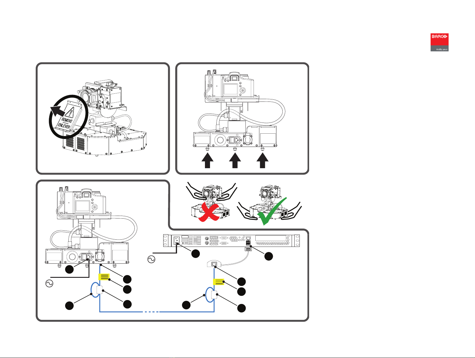
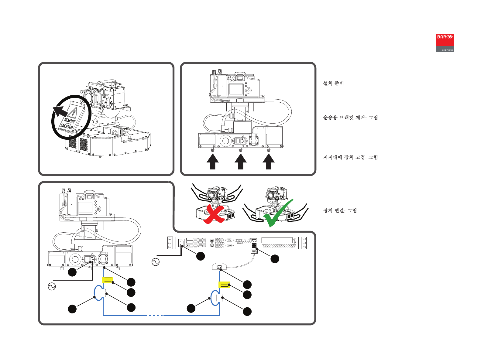
MES Acuras Head (Auto Alignment Head)
Guia de iniciação rápida
Divisão Barco Simulation
Noordlaan 5, B-8520 Kuurne
www.barco.com
Início
Partimos do princípio de que o software XDS RACU foi
instalado e de que foi importado o Ficheiro de Licença cor-
recto, incluindo as opções de Auto-alinhamento adquiridas.
Consulte o manual do utilizador e de instalação R59770508
do XDS RACU.
1. Ligue a Master Control Unit (MCU) (pressione o botão
ON/OFF) e aguarde até estar totalmente carregada
2. Ligue a eRACU (pressione o botão ON/OFF durante 2
segundos) e aguarde até estar totalmente carregada
3. Ligue a Auto Alignment Head (interruptor de ligação)
4. Ligue a um Sistema de Visualização
5. Mude para o Nível de Acesso de Utilizador Administra-
tor
6. Seleccione um projector ou um grupo de projectores
7. Verifique os plugins em Options > Add/Remove Device
> Plugin Management e clique em Apply
8. Clique em Reset Gimbal na página Position > Position
Gimbal/Panel Position Marker.
Pode encontrar mais informações sobre os procedimentos
descritos em baixo no manual do utilizador e de instalação
R59770509 do Auto-alinhamento.
Configuração - Localização da Cabeça
Se uma ou mais áreas da imagem projectada estão fora do
alcance da Auto Alignment Head, deve ser definida mais de
uma posição física para esta.
A seguir a Localização Predefinida, podem ser definidas Loca-
lizações da Cabeça adicionais em Options > Auto Alignment >
General > Measurement Head Location.
Configuração - Posição Acuras
Para cada canal de visualização, podem ser definidos um
(Acuras 1-point) ou múltiplos (Acuras Multi-point) pontos de
medição na página Position:
• Acuras 1-point: utilize o ponteiro Laser para indicar o
centro de cada canal e guarde estas posições
• Acuras Multi-point:
1. Os quatro cantos exteriores e o ponto central da
área visível de cada canal têm de ser marcados (=
Marcador do Painel) e guardados
2. Utilize o ponteiro Laser para indicar o ponto de
medição em cada um dos Marcadores do Painel
e guarde estas posições (= Centro do Gimbal e
Cantos do Gimbal). O XDS RACU irá calcular mais
quatro pontos de medição (centro de cada lado
dos canais). Um desses quatro pode ficar como
indefinido.
Configuração - Posição Auto Geometry
As posições da câmara (vistas Camera Live) têm de ser
definidas de tal forma que cada canto da área visível de cada
canal esteja incluído em, pelo menos, uma posição. O tipos
de posição são:
• Sem Blend Zone: se uma posição inclui apenas canais
não sobrepostos
• Com Blend Zone: se uma posição inclui canais sobre-
postos
• HUD para definir as cantos da imagem HUD em relação
aos canais de apoio nos quais aparece.
Capturar e Realinhar Acuras
CAPTURAR
1. Crie/Active uma definição desejada de Auto-alinha-
mento
2. Execute a GLC em todos os canais a partir da Página
Adjust Gray Scale
3. Alinhe totalmente o Sistema de Visualização
4. Clique em Reset Gimbal na página Position > Position
Gimbal/Panel Position Marker
5. Na página Acuras, clique em Start Capture.
REALINHAR
1. Active a definição Auto-alinhamento desejada para a
qual a Captura foi executada
2. Clique em Reset Gimbal na página Position > Position
Gimbal/Panel Position Marker
3. Na página Acuras, clique em Start Realignment.
Captura AutoGeometry
CAPTURAR (se nenhuma posição for do tipo HUD)
1. Clique em Reset Gimbal na página Position > Position
Gimbal/Panel Position Marker
2. Na página AutoGeometry, clique em Capture.
CAPTURAR (se pelo menos uma posição for do tipo HUD)
1. Clique em Reset Gimbal na página Position > Position
Gimbal/Panel Position Marker
2. Certifique-se de que todos os projectores obtêm uma
imagem preta do respectivo IG e de que o projector
HUD mostra um rectângulo branco preenchido na área
de interesse HUD do IG
3. Na página AutoGeometry, clique em Capture.
Observações importantes
• Efectue sempre uma reinicialização do Gimbal após ligar
a Auto Alignment Head
• Não são permitidas luzes de dispersão durante uma
Captura ou um Realinhamento.
Visão Geral
Acuras é usado para guardar as definições de luminosidade
e de cor por canal num conjunto de dados Golden Alignment
após o alinhamento total de um Sistema de Visualização
efectuado por um profissional da Barco (= Captura) e para
reproduzir o "aspecto" Golden Alignment da melhor forma
possível, para corrigir o desvio provocado pelo envelhecimen-
to das lâmpadas, filtros, etc. (Realinhamento). Os pontos de
medição (Posições) para o espectrómetro têm de ser defini-
dos antes de ser possível efectuar uma Captura.
AutoGeometry é usada para obter as coordenadas X e Y dos
cantos da área visível de cada canal de visualização (= Captu-
ra). As posições da câmara têm de ser definidas antes de ser
possível efectuar uma Captura.
R59770598PT_02
18 de Marcha de 2011