Manual 2100-764
Page 6 of 8
“Y1” Potentiometer setting: Not applicable on this
model.
“Y2” Potentiometer setting: Not applicable on this
model.
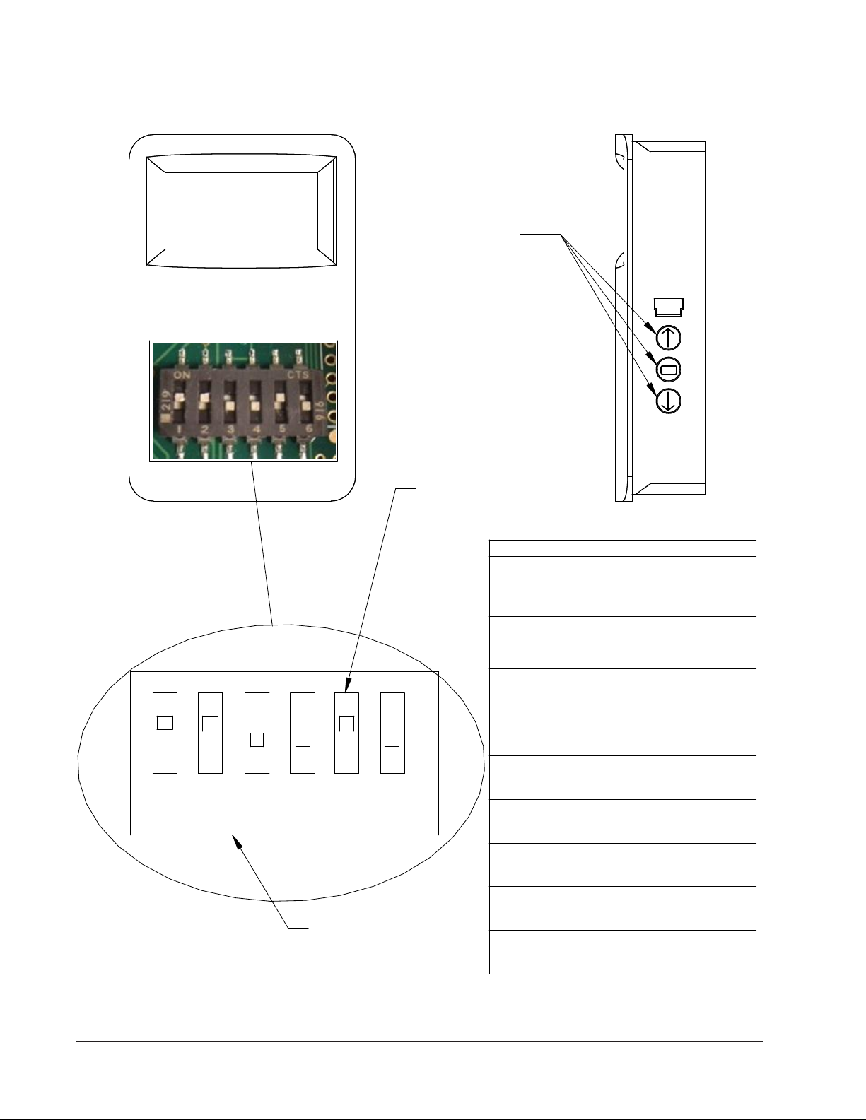
2-10V Operation
A CO2sensor or other device sending a 2-10V signal
can be used to control the damper motor. Two control
methods are available to control the damper motor:
• Method 1: The control board will accept a
2-10VDC signal with a resistive load greater than
5000 ohms. Bard CO2sensor part #8403-096 can
be used when the 2-10V output is connected to
the "CO2 V IN" tab on the CRV control board. The
pre-purge "PP" and occupied "OCC" potentiometer
settings must be set to the off position and pre-
purge jumper must be set to "0" position for total
modulation. The OCC potentiometer can be used
to maintain a minimum blade position when "3" is
energized.
• Method 2: The damper motor will accept a
2-10VDC signal with a resistive load less than
5000 ohms. This method involves bypassing the
control board and powering the motor directly from
the device providing the 2-10VDC modulating
signal. The 1/4" tab connector of the white wire
coming from the damper motor lead must be
disconnected from the CRV control board wiring.
The 2-10V signal coming from the CO2controller
must be connected to this wire.
During 2-10VDC operation with "3" energized and
pre-purge timed operation active, DC voltage signaling
occupancy from a source such as a CO2sensor will
increase ventilation amounts as needed.
Adding Optional Co2Control Sensor
Adding an optional CO
2
control sensor (Bard Part
#8403-096) to this control will maximize the
capabilities of this vent by only supplying fresh air intake
to maintain CO
2
levels. This has multiple benets.
• Minimizes ventilation load on structure as it only
brings in what is required to maintain CO2levels
thus lowering reconditioning requirements (not
having to heat/cool as much outside air).
• Will self-adjust for various occupancy levels so
that fresh air is not being brought in beyond need.
For example, if a room is designed for a maximum
occupancy of 40 persons (standard ventilation
control would have to be set for that occupancy),
but the room typically only contains 25 persons.
This control will self-adjust the amount of fresh air
intake from 600 to 375 CFM automatically (based
upon 15 CFM per person standard rate to ASHRAE
standards).
Basic Installation
1. Make sure power is turned off to the unit
2. Run four (4) wire thermostat wire from the unit to
the desired CO2sensor location.
3. Follow Figure 5 on page 8 to congure the CO2
sensor for proper operation.
4.
Connect the thermostat wiring from the CO
2
sensor
to step control assembly following the wiring diagram
in Figure 4 or the one on the ventilator assembly.
5. To check operation, restore power to the unit.
6. Make sure that thermostatic control is in
“occupied” mode of operation calling for
ventilation. Terminal “3” on the low voltage
terminal strip must be energized to open damper.
7. Have someone stand in front of the CO2sensor
and breathe on it. The display should show an
increase in CO2ppm, and the damper blade in the
ventilation package should increase. (It may be
best to have two people to do this—one to breathe
on control and one to observe damper.)