BARKER AND STONEHOUSE P0LPCORNBRWN User manual

ASSEMBLY INSTRUCTIONS
IMPORTANT NOTICE
THIS BOOKLET CONTAINS USEFUL INFORMATION
ABOUT WARRANTY & CARE INSTRUCTIONS.
PLEASE KEEP FOR FUTURE REFERENCE.
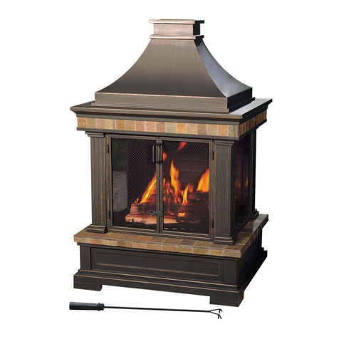
COMPACT POLPERRO FIREPIT TABLE
SKU: P0LPCORNBRWN / P0LPCORNGREY
BSH-RCD-004B / BSH-RCD-004G

ASSEMBLY INSTRUCTIONS
2
PARTS LIST
Table Box
Part Qty Part Name
A 2 Leg Panel
B 1 Table Top
C 1 Side Panel With Door
D 1 Side Panel With Control Hole
E 1 Glass
F12 M6 x 20mm
G12 Washer
H 1 Allen Key
A
C ED
x2
x1
Fx12 Gx12 Hx1
x1 x1
Bx1

ASSEMBLY INSTRUCTIONS
3
PARTS LIST
Firepit System Box
Windguard Box
Part Qty Part Name
I 1 Firepit System
J 1 Stainless Steel Lid Cover
K 1 Onyx Coloured Fireglass
L 4 Square Winguard Panel
M 4 Top Connector For Windguard
N 4 Bottom Connector For Windguard
Ix1 Jx1 Kx1
Lx4 Mx4 Nx4

4
ASSEMBLY INSTRUCTIONS
ASSEMBLY ADVICE - READ BEFORE YOU START!
• NEVER use power drills when assembling the table, firepit and windguard.
• Ensure that you read this manual before starting to assemble your table.
• Check that you have all parts from the parts list. Do not throw away any packaging
until you are confident that you have all parts.
• Assemble this product on a soft/flat surface.
• Place the table glass safely to one side until it is required and never lay the glass
on hard or rough surfaces during assembly.
• It is recommended that two people lift the glass. Ensure you lift with the correct
posture & technique.
• Keep any plastic bags, tools, and fittings away from children and pets.
• After prolonged use we recommend you check all the fittings are tightened
securely.
• Please do not modify this product, use other tools, or substitute parts to build your
item(s), as this will void your warranty.
• Please only use this product for its intended purpose as outdoor furniture within a
residential environment. Failure to do so will void your warranty.
• Barker And Stonehouse holds no responsibility for any damages caused due to
normal wear and tear, incorrect assembly, misuse and/or negligence.
• We reserve the right to make changes for product improvements.
• Please recycle packaging where possible.

5
ASSEMBLY INSTRUCTIONS
GAS FIREPIT SAFETY ADVICE - READ BEFORE YOU START!
• ONLY a 5kg Patio Gas Bottle can be used in conjunction with this firepit.
Using any other size will invalidate your warranty and will damage your
product.
• Perform a visual inspection of all fixings ensuring they are all securely tightened
before using the system for the first time.
• When using your gas firepit table, operate on solid ground only.
• The gas firepit table can only be used outdoors, in a well-ventilated area.
• The gas system must be checked and serviced yearly, by a qualified gas
safety engineer.
• NEVER add any fuel to the burner tray.
• 1 x AAA battery must be inserted into the ignition ensuring the negative side is
inserted first.
• Ensure the black wire from the system is connected to the igniter.
• Make sure the gas supply is switched off before changing the battery in the
ignition.
• Turn off the gas supply after each use.
• Only ONE gas bottle can be stored under the table when in use.
• If you smell gas, turn off the gas supply immediately, open the lid and ventilate the
area.
• The windguard is purely that and will not prevent the surrounding area from
heating up. It prevents the flame from being blown across the table only and it will
get hot.
• The fire glass is heat resistant and is for decoration to cover the pan and firepit
system. The ring burner can be covered in crushed glass. However, the pilot cover
cannot be covered or the flame will fail to ignite.
• The system should be kept clean at all times and can be cleaned with a damp
cloth.
• To release the gas bottle you press the button under the regulator. This will only
work if the gas is switched off.
• For further gas safety information refer to the instructions within the gas system.

ASSEMBLY INSTRUCTIONS
6
ASSEMBLY
STEP 1
Loosely secure the leg panel onto the table top using the M6 x 20mm screws
and washers. Do not tighten any screws at this step.
A
B
A B F G H
x2x1x1 x2 x1
G
H
F

ASSEMBLY INSTRUCTIONS
7
ASSEMBLY
STEP 2
Loosely secure the second leg panel onto the table top using the M6 x 20mm
screws and washers. Do not tighten any screws at this step.
A
G
H
F
B
A B F G H
x2x1x1 x2 x1

ASSEMBLY INSTRUCTIONS
8
ASSEMBLY
STEP 3
Loosely secure the side panel with door to the inside of the legs using the M6
x 20mm screws and washers. Do not tighten any screws at this step.
CF G H
x4x1 x4 x1
C
G
H
F

ASSEMBLY INSTRUCTIONS
9
ASSEMBLY
STEP 4
Loosely secure the side panel to the inside of the legs using the M6 x 20mm
screws and washers.
D
G
H
F
D F G H
x4x1 x4 x1
ITS TIME!
Now tighten all the screws with the
provided Allen key.

1110
ASSEMBLY INSTRUCTIONS
ASSEMBLY
STEP 5
Turn the table over. Position the glass onto the table top ensuring the suction
rings are flat.
E
E
x1
SAFETY WARNING!
Always lift and secure the glass with
two people.
COMPLETE!
Assembly of the table is now
complete!

ASSEMBLY INSTRUCTIONS
11
FIREPIT SYSTEM ASSEMBLY
G
I I
x4 x1
STEP 1
Remove the firepit system control panel nuts. Keep the nuts to one side.

ASSEMBLY INSTRUCTIONS
FIREPIT SYSTEM ASSEMBLY
12 13
STEP 2
Lower the gas firepit system into the centre of the table, on top of the glass.
Position the regulator, hose and control panel through the table hole before
lowering the system onto the glass edge.
I
E
I
x1
SAFETY WARNING!
Ensure the gas pipes under the
table are not kinked and all wiring
is connected.

ASSEMBLY INSTRUCTIONS
13
FIREPIT SYSTEM ASSEMBLY
STEP 3
Attach the firepit control panel to the table base. Tighten the control panel onto
the frame using the previously removed nuts.

ASSEMBLY INSTRUCTIONS
14
FIREPIT SYSTEM ASSEMBLY
STEP 4
Carefully fill the firepit system with the fireglass. Ensure the pilot cover is not
obstructed. Position the firepit lid into the space around the firepit centre.
(Always remove the lid before lighting the firepit).
K
x1
J K
K

ASSEMBLY INSTRUCTIONS
15
FIREPIT SYSTEM ASSEMBLY
STEP 5
Remove the battery cover. Place 1 x AAA battery into the ignition, ensuring the
negative side is inserted first. Once inserted, add the battery cover back onto
the control panel.
1. 2.
3.
Positive End
Negative End
COMPLETE!
Assembly of the firepit system is
now complete!

CAUTION!
Handle the glass with care when
assembling.
ASSEMBLY INSTRUCTIONS
WINDGUARD ASSEMBLY
16 17
STEP 1
Loosen all the grub-screws in the connectors with a Phillips screwdriver (not
supplied). Loosely position each windguard panel, one at a time, using the
top and bottom connectors until a rectangular windguard is formed. Do not
tighten any screws until the windguard is formed.
L
M
x4
N
x4
L
x4

WINDGUARD ASSEMBLY
ASSEMBLY INSTRUCTIONS
17
SAFETY ADVICE
We recommend tightening the
grub-screws occasionally after
use.
STEP 2
Once the windguard is formed tighten all the grub screws using a Phillips
screwdriver and position the windguard roughly 2cm around the edge of the
firepit system.
COMPLETE!
Assembly of the windguard is now
complete!

ASSEMBLY INSTRUCTIONS
18
GAS FIREPIT SYSTEM LEAK TEST
NEVER USE AN OPEN FLAME TO TEST FOR LEAKS AT ANYTIME.
A GAS LEAK TEST MUST BE PERFORMED BEFORE FIRST USE OF THE
GAS FIREPIT SYSTEM.
(Perform in a well ventilated area)
1. Confirm all appliance control knobs are in the off position.
2. Open the gas control valve on the gas bottle.
3. Check for leaks by brushing soap solution over all gas system joints,
Including all valve connections, hose connections and regulator
connections. If bubbles form over any of the joints, there is a leak. Turn off
the gas supply and retighten that joint.
4. Repeat the test.
If the bubbles form again STOP trying and contact your local retailer for
assistance.
LEAK TEST ANNUALLY AND WHENEVER THE GAS BOTTLE IS
REMOVED OR REPLACED.

ASSEMBLY INSTRUCTIONS
19
BEFORE LIGHTING YOUR FIREPIT
• Check all fixings on the gas firepit system are
securely tightened before first use.
• Ensure a 5kg patio gas bottle is used with the
gas firepit system.
• Ensure the gas bottle is not placed directly
under the firepit system.
• Ensure the gas bottle measures no more than
39cm tall.

ASSEMBLY INSTRUCTIONS ASSEMBLY INSTRUCTIONS
20 21
BEFORE LIGHTING YOUR FIREPIT
• 1 x AAA battery must be inserted into the
ignition, position within the control panel.
• Ensure the black wire from the system is
connected to the igniter.
• Check the table is positioned on flat, solid
ground.
• Ensure the pilot cover is free from the crushed
fireglass.
Other manuals for P0LPCORNBRWN
1
This manual suits for next models
3
Table of contents
Other BARKER AND STONEHOUSE Outdoor Furnishing manuals