Barnstead Mega-Pure Series 798 User manual

MEGA-PURE®
One Liter Water Still
OPERATION MANUAL
AND PARTS LIST
SERIES 798
LT798X1 • 9/8/05
Model Number Voltage Description
A440266 120V Without Bottle
A440267 120V With Bottle
A7981 240V Without Bottle
A7982 240V With Bottle

2
Important Information
This manual contains important operating and safety information. You must carefully read and understand the
contents of this manual prior to the use of this equipment.
Water purification technology employees one or more of the following: chemicals, electrical devices, mer-
cury vapor lamps, steam and heated vessels. Care should be taken when installing, operating or servicing
Barnstead products. The specific safety notes pertinent to this Barnstead product are listed on page 4.
Figure 1 MEGA-PURE One Liter Still

3
Ta ble of Contents
Important Information....................................................................................................................................2
Ta b le of Contents..........................................................................................................................................3
Safety Information ........................................................................................................................................4
Alert Boxes ............................................................................................................................................4
Warnings ................................................................................................................................................4
Introduction ..................................................................................................................................................6
Unpacking ....................................................................................................................................................7
Installation and Service Requirements ........................................................................................................8
Location of Unit ......................................................................................................................................8
Service Requirements............................................................................................................................8
Power......................................................................................................................................................9
Water Supply Requirements ..................................................................................................................9
Drain ....................................................................................................................................................10
Initial Assembly ..........................................................................................................................................10
Feedwater Connections ..............................................................................................................................11
Tap Water Boiler Feed..........................................................................................................................11
Pretreated Boiler Feed ........................................................................................................................12
Demineralizer Treated Boiler Feed ......................................................................................................13
In-House Treated Boiler Feed ............................................................................................................14
Still Output Connections ............................................................................................................................16
Storage Bottle Installation ....................................................................................................................16
Automatic Collection System Installation ............................................................................................17
Operation ....................................................................................................................................................18
High Temperature Cut-off Switch ........................................................................................................19
Maintenance and Servicing ........................................................................................................................20
Cleaning ..............................................................................................................................................20
Tr oubleshooting ....................................................................................................................................21
General ................................................................................................................................................21
Electrical ..............................................................................................................................................23
Still Troubleshooting ............................................................................................................................23
Automatic Collection System Troubleshooting ....................................................................................24
Parts List ....................................................................................................................................................25
Parts arranged by Exploded View key number ....................................................................................25
Exploded View ............................................................................................................................................26
Wiring Diagram ..........................................................................................................................................27
Ordering Procedures ..................................................................................................................................28
One Year Limited Warranty ........................................................................................................................32

4
Your Barnstead MEGA-PURE One Liter Water Still has been
designed with function, reliability, and safety in mind. It is your
responsibility to install it in conformance with local electrical
codes. For safe operation, please pay attention to the alert
signals throughout the manual.
Warnings
To avoid electrical shock, always:
1. Use a properly grounded electrical outlet of correct
voltage and current handling capacity.
2. Ensure that the equipment is connected to electri-
cal service according to local and national stan-
dards. Failure to properly connect may create a fire
or shock hazard.
3. Do not mount the MEGA-PURE One Liter Water
Still directly over equipment that requires electrical
service. Routine maintenance of this unit may
involve water spillage and subsequent electrical
shock hazard if improperly located.
4. Replace fuses with those of the same type and rat-
ing.
5. Disconnect from power supply before servicing.
6. Do not connect unit to electrical service until
instructed to do so.
To avoid personal injury:
1. Do not use in the presence of flammable or com-
bustible materials; fire or explosion may result. This
device contains components which may ignite such
materials.
2. Wear eye and hand protection when using acid for
cleaning, as acid spattering may occur.
3. Use this device with water feed only. Failure to
comply with the above could result in explosion
and personal injury.
4. Ensure all piping connections are tight to avoid
leakage of chemicals.
Safety Information
Warning
Warnings alert you to a possibility of
personal injury.
Caution
Cautions alert you to a possibility of
damage to the equipment.
Note
Notes alert you to pertinent facts
and conditions.
Alert Signals

5
5. Always depressurize chemical lines before disas-
sembly.
6. To avoid exposure to chemical fumes, ensure ade-
quate ventilation when using chemicals for clean-
ing.
7. Follow carefully the manufacturers’ safety instruc-
tions on labels of chemical containers and Material
Safety Data Sheets (M.S.D.S.).
8. “Caution - Hot Surface. Avoid Contact.” Glass por-
tions of still become hot when still is operating. To
avoid burns, do not touch hot glass.
9. Refer servicing to qualified personnel.
C. To ensure safe mounting:
1. Wall composition and construction, as well as fas-
tener type, must be considered when mounting this
unit. The mounting surface and fasteners selected
must be capable of supporting a minimum of 60
lbs.; inadequate support and/or fasteners may
result in damage to mounting surface and/or equip-
ment. If you are unsure of mounting surface com-
position, condition and construction, or correct fas-
teners, consult your building maintenance group or
contractor.
SAFETY INFORMATION
6
Your Barnstead MEGA-PURE One Liter Water Still is a com-
pact, all glass unit with PTFE connectors designed to provide
1.4 liter per hour of high purity distilled water. The product
water is non-pyrogenic per USP XIX. Resistivity will be
greater than 1.0 megohm-cm at the condenser outlet using
most tap water as feed. This water still can be used as a dis-
crete unit or with customer supplied pretreated water. It can
also be connected to the Barnstead Automatic Collection
System for completely automatic operation.
Your MEGA-PURE One Liter Water Still allows you to
replace tap water boiler feed with demineralized, distilled or
R.O. water for low maintenance operation and high purity dis-
tillate. Distilled water storage can be easily handled in the
optional 6-liter polyethylene or 9-liter Pyrex brand storage bot-
tle. Either fits conveniently inside the water still cabinet and
dispenses distilled water through a valve which is accessible
at the front of the still.
Choice of a location for your MEGA-PURE One Liter Water
Still is primarily a matter of convenience. This unit may be
located on a bench or wall mounted.
Your MEGA-PURE One Liter Water Still is rated at either
120 volts, 50/60 Hz, 1000 watts, single phase or 240 volts,
50/60 Hz, 1000 watts, single phase. This unit requires approx-
imately 11 to 15 liters per hour of cooling water.
The cabinet and glassware are protected against damage
from overheating by a thermal switch.
Introduction
Warning
Use a properly grounded electrical outlet
of correct voltage and current handling
capacity.
Ensure that the equipment is connected
to electrical service according to local
and national standards. Failure to prop-
erly connect may create a fire or shock
hazard.
Do not mount the MEGA-PURE One
Liter Water Still directly over equipment
that requires electrical service. Routine
maintenance of this unit may involve
water spillage and subsequent electrical
shock hazard if improperly located.
Do not connect unit to electrical service
until instructed to do so.
Note
Operation of the still at a voltage
less than the stated voltage will
cause a drop in still output.

7
Tools required: Diagonal cutting pliers.
1. Remove parts box and still from shipping carton
and place on workbench.
2. Check glassware inside the main cabinet for
damage. Check parts in the accessory box for
damage. Identify any broken or damaged parts
and report them to your dealer immediately.
Refer to Figure 1 (page 2) for the following step:
3. Using diagonal cutting pliers, cut and remove
the five (5) plastic shipping ties. The shipping tie
locations are: Two (2) on the condenser "B", two
(2) on the boiler "I", and one (1) on the trap "N."
Unpacking

8
Installation and Service
Requirements
Location of Unit
Choice of location for the MEGA-PURE One Liter Water Still
is primarily a matter of convenience as long as the service
requirements, listed on the next page, are met.
A. The still may be bench or wall mounted. Allow 4"-
6" clearance at the sides and top for circulation of
ambient air to prevent buildup of heat in the cabi-
net.
B. Unit Dimensions: 18" wide x 10" deep x 34" high.
C. Wall Mounting: The still is supplied with slotted
mounting holes located 16" on center in the rear of
the cabinet and
22 7/8" from the bottom. The weight of the unit with
a full storage bottle is 45-60 lbs.
Service Requirements
Power
Your water still is supplied with a power cord (5 feet long) and
plug. The plug on the 120V unit requires a standard North
American 120V, 15A, 3-prong receptacle. The plug on the
240V unit requires a standard European 240 volt receptacle.
(See Figure 2.) If you do not have the required receptacle
available within 5 feet of your still, a certified electrician
should install one in accordance with local and national stan-
dards. As an alternate method of power supply for a 240 volt
unit, your electrician may remove the supplied plug and wire
the cord to a 15A-250V breaker box.
(See Figure 3.)
Water Supply Requirements
Barnstead recommends one of the following options for sup-
plying water to operate your MEGA-PURE One Liter Water
Still.
OPTION #1
A single, untreated cold water supply. The supply must be
capable of providing a minimum of 4 gallons (15 liters) per
hour at a pressure of 20-100 psi and be located within 4 feet
(1.2 meters) of the MEGA-PURE One Liter Water Still. You
must provide a shut off valve and reducer as shown in Figure
4.
Warning
Do not mount the MEGA-PURE One
Liter Water Still directly over equip-
ment that requires electrical service.
Routine maintenance of this unit
may involve water spillage and sub-
sequent electrical shock hazard if
improperly located.
Wall composition and construction,
as well as fastener type, must be
considered when mounting this
unit. The mounting surface and
fasteners selected must be capable
of supporting a minimum of 60 lbs.;
inadequate support and/or fasteners
may result indamage to mounting
surface and/or equipment. If you are
unsure of mounting surface com-
position, condition and construction,
or correct fasteners, consult your
building maintenance group or con-
tractor.
Warning
Ensure that the equipment is con-
nected to electrical service accord-
ing to local and national standards.
Failure to properly connect may cre-
ate a fire or shock hazard.
Do not connect unit to electrical ser-
vice until instructed to do so.

9
Figure 2 240 Volt Receptacle
Figure 3 15A - 250V Breaker Box
Ground
Line
Line
With Option #1, approximately 4 gallons of untreated water
will be used per hour in the cooling section of the still, 1 gal-
lon of this water will be used as boiler feed. Water connec-
tions are discussed on pages 11-15.
OPTION #2
An untreated cold water supply plus a source of RO, dem-
ineralized or previously distilled water. The untreated supply
must be capable of providing a minimum of 4 gallons (15
liters) per hour at a pressure of 20-100 psi and be located
within 4 feet (1.2 meters) of the water still. The treated supply
must be capable of providing 1 gallon (3.75 liters) per hour
and be located within 4 feet of the water still. You must pro-
vide a shut-off valve and reducer at each water supply (see
Figure 4). In addition you will require the optional double sole-
noid valve kit (Catalog No. RY798X2A (120V) or 440236
(240V)).
With Option #2, approximately 4 gallons of untreated water
will be used each hour for cooling. The second (treated) water
supply of 1 gallon per hour will be used as boiler feed. Water
connections are discussed on pages 11-15.
Drain
An open or atmospherically vented drain located lower than
the still is necessary to allow for gravity flow. Barnstead sup-
plies a 5 foot length of 1/2" I.D. vinyl tubing for the drain.
Additional tubing may be purchased from your laboratory
dealer.
INSTALLATION AND SERVICE REQUIREMENTS
Load
(Blue Wire)
Line Ground
Load Ground
(Green Wire)
Line
Load
(Brown Wire)
Water
Supply
Reducer
2" - 3" Length of pipe
with 1/8" N.P.T.
Figure 4 Shut-off Valve
Note
The double solenoid valve kit is not needed
if you are using a MEGA-PURE D1 or D2
deionizer for pretreatment.

10
Tools required for assembly: 7/16" open end wrench, diagonal
cutting pliers, common screwdriver.
1. Unwrap the condenser “B” and thoroughly flush all
of the salt out.
2. Reattach the condenser “B” to the still and then
attach the two PTFE connectors “D” and “P” to the
condenser “B” as shown in Figure 1.
3. Check orientation of trap "N." If it is not level or tilt-
ed back toward the boiler as shown in Figure 1,
move the condenser "B" up in its bracket. This will
tilt trap as shown in Figure 1.
4. Remove the packing material and rotate tube "L"
into the constant level chamber of boiler "I" as
shown in Figure 1.
5. Unpack the Vycor®immersion heater "M" and
check the voltage rating on the top cap. It should
agree with the voltage of your power supply. If it
does not, contact your dealer and order the correct
heater.
6. Insert the immersion heater into the top opening of
boiler "I" as shown in Figure 1.
7. Thread the heater plug and cord through the large
hole above the boiler "I," then back through the
hole below the control box "H." Plug heater plug
into the receptacle on the bottom of the control
box. The plug is twist-lock type and requires 1/4
clockwise turn to lock in place.
Initial Assembly
Figure 5 Control Bottom Connections
Solenoid Power
Receptacle
Heater Power
Receptacle
MEGA-
PURE
Deionizer
Control
Receptacle
ACS Control
Receptacle

11
This still always uses tap water for cooling the steam in the
condenser. However, you have the option of feeding your boil-
er with higher purity pretreated water, thereby reducing the
need to drain and clean your boiler.
If you will be using tap water as your boiler feedwater, pro-
ceed to the Tap Water Boiler Feed section. If you will be using
a supply of distilled, deionized or reverse osmosis water as
your boiler feed, proceed to the Pretreated Boiler Feed sec-
tion.
Tap Water Boiler Feed
See Figure 6
1. Install a customer supplied shutoff valve onto your
tap water source. Thread the solenoid valve onto
your customer supplied shutoff, with the side
marked “in" toward the shutoff.
2. Install the supplied fitting to the “out” side of the
solenoid valve. Connect the 5/16" I.D. tubing (from
the condenser) to this fitting.
3. Route 3/8" I.D. vinyl drain tubing to an atmospheri-
cally vented drain.
Feedwater Connections
Figure 6 Tap Water Feed Only
Note
Barnstead strongly recommends that
you install the optional flowmeter
(Catalog Number 440092) into your
feedwater line(s). This will allow you
to control the flow of water to your
still easily and precisely.

12
4. Plug the solenoid valve power cord (not shown)
into the receptacle on the bottom of the control box
"H." (See Figure 5.)
5. Go to the Still Output Connections section to com-
plete your still's setup.
Pretreated Boiler Feed
When a supply of distilled, deionized or reverse osmosis
water is to be used as boiler feed, first revise the still connec-
tions as follows:
1. Remove boiler fill tube "O" from still and set aside.
2. Locate the 3/8" I.D. x 44" long vinyl tubing and one
barbed tee (3/8" I.D. x 3/8" I.D. x 3/8" I.D.) in the
parts box.
3. Install one end of the vinyl tubing to the cooling
water outlet located on the top right of the con-
denser "B" (where boiler fill tube "O" was
attached). Route the other end through the cabinet
and down the back as shown in Figure 7.
4. Cut the 3/8" I.D. vinyl drain tubing and install the
barbed tee. Connect the 3/8" I.D. vinyl tubing from
condenser to the barbed tee. Push the vinyl tubing
all the way onto the tee to assure a leak free seal.
5. Route the drain tubing to an atmospherically vent-
ed drain.
If you will be using a MEGA-PURE D1 or D2 demineralizer to
provide pretreated boiler feed, go to the Demineralizer
Treated Boiler Feed section. If you will be using an "in-house"
source of pretreated water for boiler feed, go to the In-House
Treated Boiler Feed section.
FEEDWATER CONNECTIONS
Figure 7 Tubing Connections

13
Demineralizer Treated Boiler Feed
See Figure 8. (Must have optional still adapter kit: Catalog No.
440376)
1. Install a customer supplied shutoff valve onto your
tap water source. Thread the solenoid valve onto
your customer supplied shutoff, with the side
marked “in" toward the shutoff.
2. Install the fitting supplied with the still adapter kit
into the “out” side of the solenoid valve. Connect
the 1/4" O.D. tubing (from the demineralizer) to this
fitting.
3. Cut the 1/4" O.D. tubing (from last step) at a con-
venient point and install the tee from the still
adapter kit (Catalog No. 440376).
4. Connect a length of 1/4" O.D. tubing to the third
arm of the tee. Connect the 1/4" O.D. to 3/8" I.D.
adapter to the free end of this length of 1/4" O.D.
tubing. Connect the
5/16" I.D. tubing (from the condenser) to this
adapter.
5. Locate boiler fill tube "L." Connect 7/16" I.D. vinyl
tubing from demineralizer output to end of boiler fill
tube. Route as shown and install clip "S" to sup-
port the tubing.
FEEDWATER CONNECTIONS
Figure 8 Deionizer Feed
Note
If using the optional flowmeter,
install it at this point instead of the
adapter.

14
6. Route 3/8" I.D. vinyl drain tubing to atmospherically
vented drain.
7. Plug solenoid valve power cord (not shown) into
receptacle in control box "H."
8. Plug still adapter kit cable into right side of dem-
ineralizer and receptacle in control box "H."
9. Go to the Still Output Connections section on page
16 to complete the setup of your still.
In-House Treated Boiler Feed
See Figure 9. (Must have optional double solenoid valves:
Catalog No. 440236 (240V), RY798X2A (120V))
1. Install customer supplied shutoff valves onto your
tap water source and your in-house treated water
source. Thread the solenoid valves onto your cus-
tomer supplied shutoffs, with the sides marked “in"
toward the shutoffs.
2. Install the supplied 5/16" fitting to the “out” side of
the solenoid valve on your tap water source.
Connect the 5/16" I.D. tubing (from the condenser)
to this fitting.
FEEDWATER CONNECTIONS
Figure 9 In-house Treated Feed

15
3. Connect the 3/8" fitting and 3/8" I.D. vinyl tubing
from the double solenoid valve kit to the “out” side
of the solenoid valve on your treated water supply.
4. Locate the boiler fill tube "L." Connect 3/8" I.D.
from treated water supply solenoid to the end of
the boiler fill tube. Route as shown and install clip
"S" to support the tubing.
5. Route the 3/8" I.D. vinyl drain tubing to an atmos-
pherically vented drain.
6. Plug the solenoid valve power cord (not shown)
into the receptacle in control box "H" (See Figure
5.)
7. Go to the Still Output Connections section on page
16 to complete the setup of your still.
FEEDWATER CONNECTIONS
16
If you are using one of the optional Storage Bottles, go to the
Storage Bottle Installation section. If you are connecting your
still to an Automatic Collection System, go to the Automatic
Collection System Installation section.
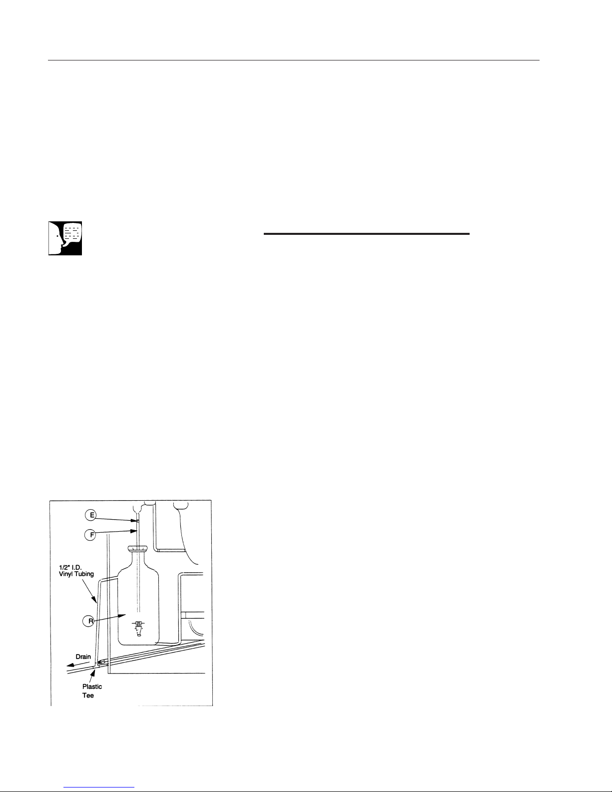
Storage Bottle Installation
To install the optional 6 or 9 liter storage bottle inside the one
liter still cabinet, first locate the following parts in the storage
bottle parts box:
Product delivery tube "F"
PTFE Connector "E"
20" length of 1/2" vinyl tubing
Plastic tee (1/2 X 1/2 X 1/2)
1. Place storage bottle (with product delivery tube "F"
installed) inside still cabinet below condenser "B."
Connect product delivery tube to condenser with
PTFE connector "E."
2. Locate plastic tee (1/2 x 1/2 X 1/2) and 20" length
of 1/2" vinyl tubing in parts box. Connect to bottle
overflow tubulation and drain as shown in Figure
10 below.
Still Output Connections
Note
The storage bottles do not automati-
cally control the still.
Figure 10 Storage Bottle Installation
17
STILL OUTPUT CONNECTIONS
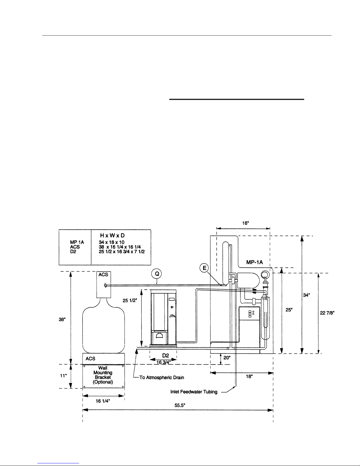
Automatic Collection System
Installation
Before connecting your MEGA-PURE One Liter Water Still to
the Barnstead Automatic Collection System, move the still to
its final location.
1. Locate ACS tube "Q" and PTFE connector "E" in
the ACS parts box. Locate distillate outlet tube
(TU798X1) in the still parts box. Assemble to tub-
ing from collection system as shown in Figure 11.
2. Plug input jack from ACS into ACS receptacle on
bottom of still control box "H." (See Figure 5)
Figure 11 Complete System Layout (Not to scale)

18
Plug electrical power cord into appropriate receptacle.
Refer to Figure 1, page 2 for referenced locations.
1. Close drain clamp "G" on bottom of boiler "I."
2. Open valve at tap water source and treated water
source if so installed.
3. Switch on the main power breaker on control at
customer power source.
4. Push “Water” switch on control box "H". Green indi-
cator will light and solenoid will open. Allow boiler
to fill.
5. Push “OPERATE” switch. Indicator will light and
heaters will come on.
6. Allow the still to operate for 15-20 minutes. For
maximum volume of distillate, increase the flow of
cooling water to the point where only a slight wisp
of steam is visible at the condenser vent "A." If you
are using a separate source of pretreated water for
your boiler feed, adjust the boiler feed flow so that
a constant overflow from the boiler is maintained.
7. Your MEGA-PURE One Liter Water Still should
now be operational. Run the still for 4-5 hours to
cleanse itself before collecting water for use.
8. To shut your water still off push the OFF switch.
This will shut the water supply and the heaters off.
If any difficulties are encountered in operating this water still,
check all operating and assembly steps to be sure the still
was assembled and is being operated correctly. If the difficulty
still exists, consult the Troubleshooting section of this manual.
Operation
Warning
Use a properly grounded electrical
outlet of correct voltage and current
handling capacity.
Ensure that the equipment is con-
nected to electrical service accord-
ing to local and national standards.
Failure to properly connect may cre-
ate a fire or shock hazard.
Do not use in the presence of flam-
mable or combustible materials; fire
or explosion may result. This device
contains components which may
ignite such materials.
Use this device with water feed only.
Failure to comply with the above
could result in explosion and person-
al injury.
“Caution - Hot Surface. Avoid
Contact.” Glass portions of still
become hot when still is operating.
To avoid burns, do not touch hot
glass.

19
High Temperature Cut-off Switch
Your MEGA-PURE One Liter Water Still is protected against
overheating by a thermal switch located in the control box at
the right hand side of the boiler. Should the boiler overheat,
the switch will open causing the heater and water supply to
shut off. When the boiler cools (5-15 minutes), the switch will
reset automatically, but the still will have to be restarted by
the operator. When unit has cooled, press the “WATER”
switch and then the “OPERATE” switch to restore normal
operation. Check boiler occasionally for proper water level.
OPERATION
Note
If you are feeding an ACS with your
still, note that when the ACS is full, it
will signal the still to shut down.
During this shut-down, the heater
and the water supply will both shut
off and the front panel lights on the
still will be extinguished. This normal
operation can mimic the effects of
an overheating boiler, but does not
represent any problem with the still.

20
Cleaning
For top performance and efficiency, the MEGA-PURE One
Liter Water Still should be kept clean and free of scale. It is
recommended that the boiler be drained and refilled with
fresh water daily to flush the boiler of the concentration of
contaminants from the previous day’s run.
When using untreated boiler feed, cleaning is recommend-
ed after every 15-20 hours of operation. The unit should be
cleaned with a hydrochloric acid solution. This is done as fol-
lows:
1. Push unit “OFF” switch.
2. Disconnect output tubing at condenser "B" from
collection vessel and temporarily place a beaker
under condenser outlet.
3. Drain boiler by opening clamp "G." Close clamp
"G" after boiler has completely drained. Refill boil-
er.
4. Use the spare pinch clamp from the parts box to
shut off overflow tube from constant level chamber
"K" as close as possible to overflow stem.
5. Carefully pour approximately 260 ml. of 10%
hydrochloric acid solution into top of constant level
chamber "K."
6. Wait approximately 10 minutes or until residue dis-
appears. If additional cleaning is required, drain
boiler down 1 inch and turn unit on for a few min-
utes until residue disappears. Do not boil. Tu r n t h e
still off.
7. Carefully drain the unit, remove clamp from over-
flow tube and refill with fresh water. Drain boiler,
refill with fresh water and operate for 30 minutes.
Reconnect tubing from collection vessel to con-
denser "B."
Maintenance and Servicing
Warning
Disconnect from the power supply
before servicing.
Wear eye and hand protection when
using acid for cleaning, as acid spat-
tering may occur.
Ensure all piping connections are
tight to avoid leakage of chemicals.
Always depressurize chemical lines
before disassembly.
To avoid lung injury or suffocation,
ensure adequate ventilation when
using chemicals for cleaning.
Follow carefully the manufacturers’
safety instructions on labels of
chemical containers and Material
Safety Data Sheets (M.S.D.S.).
Refer servicing to qualified person-
nel.
Table of contents


