Schenker MODULAR 60 User manual

COD: 60M12/24.D.2018
Installation, use and maintenance manual
Model.: Modular 60
Matriculation number: 60M12/24D
Year of construction: 2000
Schenker Italia
Via Delle Repubbliche Marinare, 67
80147 Naples Italy
Tel. +39 081 5593505
Fax. +39 081 5597372
www.schenkerwatermakers.com
THE PRESENT MANUAL BELONGS TO - Schenker Italia -ALL RIGHTS RESERVED
MODULAR 60
Digital 12/24 V dc

COD: 60M12/24.D.2018
THE PRESENT MANUAL BELONGS TO - Schenker Italia -ALL RIGHTS RESERVED
INDEX
1. LAYOUT OF MANUAL ......................................................................................................................................4
1.1 STRUCTURE OF THE MANUAL ............................................................................................................................4
1.2 DESCRIPTION OF THE PICTOGRAMS.................................................................................................................4
2. GENERAL WARNINGS AND INFORMATION TO THE RECIPIENT .....................................................5
2.1 IMPORTANT INFORMATION ................................................................................................................................5
2.2 SAFETY WARNINGS ............................................................................................................................................5
2.3WARRANTY..........................................................................................................................................................6
2.4IDENTIFICATION OF THE UNIT ..........................................................................................................................7
2.5LEGISLATIVE REFERENCE ..................................................................................................................................7
2.5.1 DIRECTIVES AND STANDARDS CONCERNING MACHINE SAFETY.................................................................7
2.5.2 RESPECT FOR THE ENVIRONMENT –REQUIREMENTS FOR REMOVAL AND DISPOSAL...............................7
3. PRODUCT PRESENTATION ............................................................................................................................9
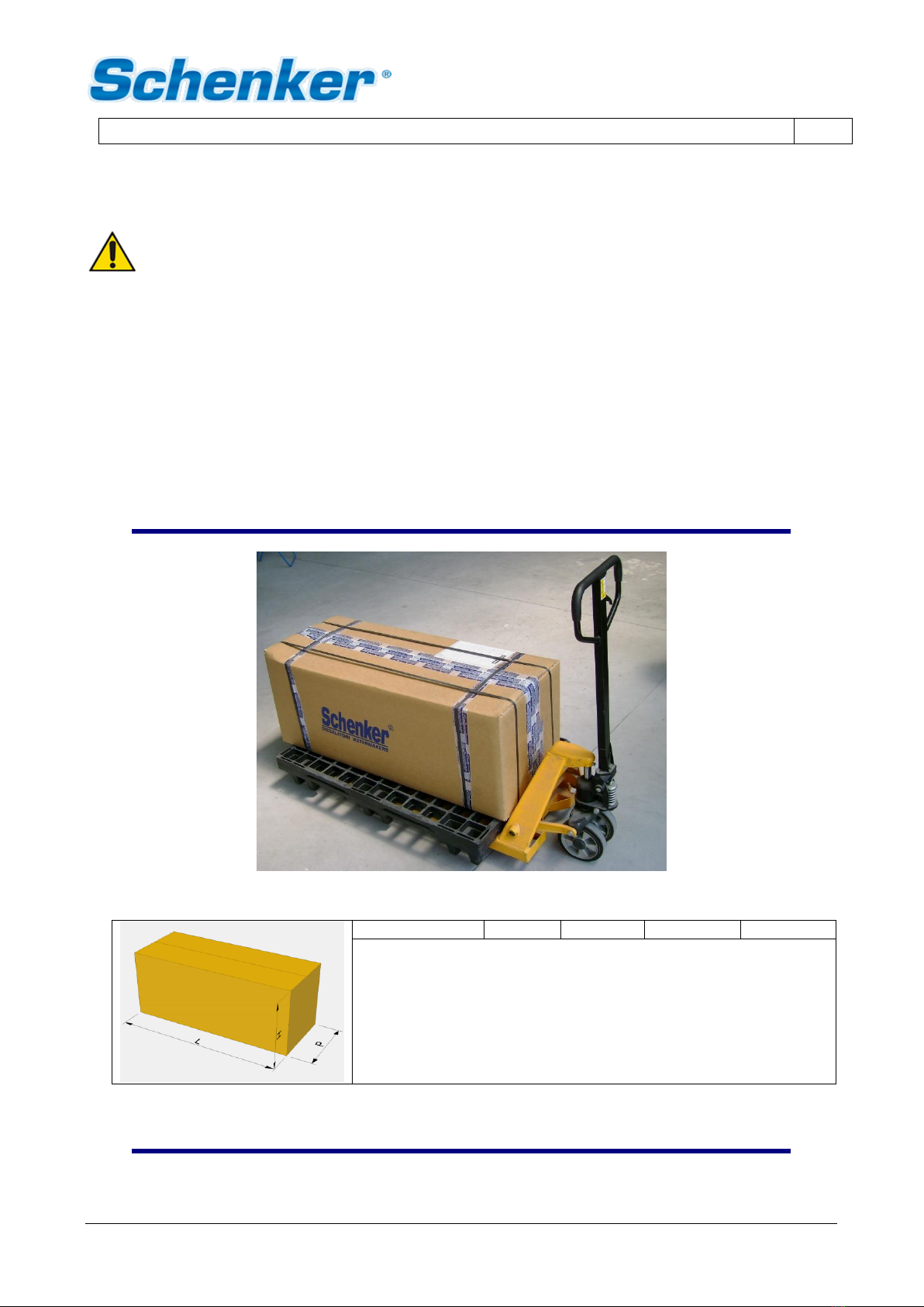
3.1 TRANSPORT AND MATERIAL HANDLING ...........................................................................................................9
3.2 STOCK ...............................................................................................................................................................10
3.3 PACKAGING.......................................................................................................................................................10
3.3.1 PACKAGING CONTENTS.................................................................................................................................10
3.4 ATTACHED DOCUMENTS ..................................................................................................................................11
3.5 TECHNICAL DATA .............................................................................................................................................11
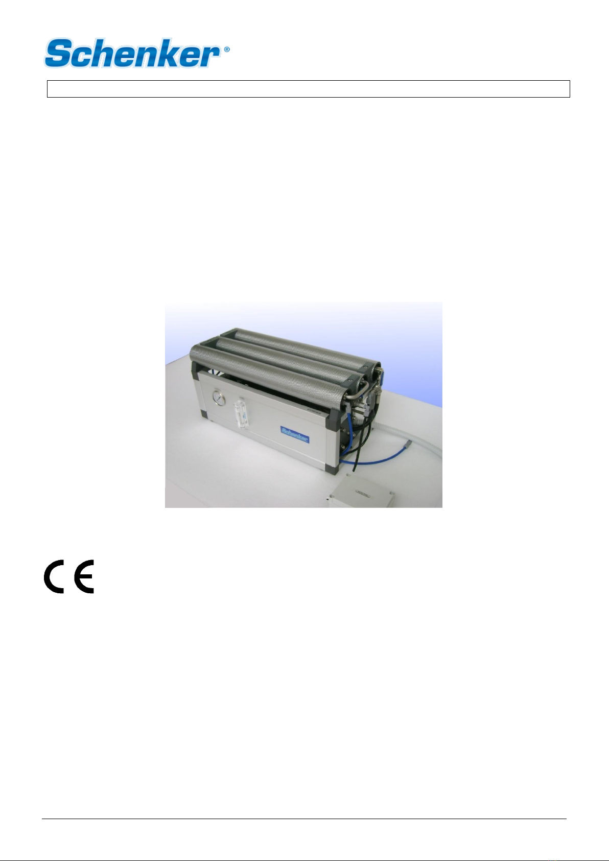
3.6 FEATURES OF THE PRODUCT ...........................................................................................................................12
3.7 ADVANTAGES OF THE ENERGY RECOVERY SYSTEM ......................................................................................13
3.8 COMPOSITION OF THE MACHINE ....................................................................................................................14
3.8.1 PUMP GROUP ..................................................................................................................................................14
3.8.2 WATERMAKER GROUP....................................................................................................................................15
3.8.3 ACCESSORIES ................................................................................................................................................20
4. MOUNTING AND INSTALLATION...............................................................................................................21
4.1 GENERAL CRITERIA ..........................................................................................................................................21
4.2 COMPONENTS MOUNTINGS .............................................................................................................................22
4.2.1 PUMP GROUP..................................................................................................................................................22
4.2.2 WATERMAKER GROUP ...................................................................................................................................22
4.2.3 ACCESSORIES................................................................................................................................................22
4.3 INSTALLATION ..................................................................................................................................................22
4.3.1 WATER INTAKES AND DISCHARGES ............................................................................................................22
4.3.2 SEAWATER INTAKE........................................................................................................................................23
4.3.3 FRESH WATER INTAKE FOR WASHING.........................................................................................................24
4.3.4 BRINE DISCHARGE ........................................................................................................................................24
4.4 HYDRAULIC CONNECTIONS .............................................................................................................................25
4.5 ELECTRIC CONNECTIONS.................................................................................................................................28
4.5.1 REMOTE CONTROL PANEL MOUNTING .........................................................................................................28
4.5.2 ELECTRIC CONNECTIONS:WIRES (MODULAR 60 12/24V DC).............................................................29
4.5.3 ELECTRIC LAYOUT SCHEME (12/24V DC)................................................................................................31
5. FUNCTIONING AND USE..............................................................................................................................32
5.1 COMMAND DESCRIPTION.................................................................................................................................32
5.2 INTRODUCTION –BY PASS MODE...................................................................................................................36
5.3 FIRST START-UP PROCEDURE .........................................................................................................................36
5.3.1 PRELIMINARY CHECKS BEFORE PROCEEDING WITH THE START-UP PROCEDURE ...................................36
5.3.2 START-UP.......................................................................................................................................................37

COD: 60M12/24.D.2018
THE PRESENT MANUAL BELONGS TO - Schenker Italia -ALL RIGHTS RESERVED
5.4 NORMAL OPERATING PROCEDURE ..................................................................................................................38
5.4.1 NORMAL OPERATING PROCEDURE WITH FINAL FLUSHING (RECOMMENDED).........................................38
5.4.2 NORMAL OPERATING PROCEDURE WITH TIMER AND FINAL FLUSHING ....................................................38
5.4.3 SINGLE WASHING OPERATION.....................................................................................................................39
5.4.4 PERIODIC WASHING......................................................................................................................................39
5.5 RESET PROCEDURE ..........................................................................................................................................40
6. MAINTENANCE (ROUTINE AND SPECIAL).............................................................................................42
6.1 CHECK FOR FILTER CLEANLINESS...................................................................................................................42
6.2 CHECK THE PLANT WORKING PRESSURE .......................................................................................................43
6.3 CHECK FOR LEAKS............................................................................................................................................43
6.4 CHECK FOR MEMBRANES REPLACEMENT ........................................................................................................43
6.5 SHUTDOWN PROCEDURE .................................................................................................................................43
6.5.1 NECESSARY EQUIPMENT ..............................................................................................................................44
6.5.2 SHUTDOWN OPERATING PROCEDURE..........................................................................................................45
6.6 ANTIFREEZE PROCEDURE (WINTERIZING PROCEDURE IN COLD CLIMATE -UNDER 5°C).......................47
6.7 PERIODIC MAINTENANCE.................................................................................................................................48
6.7.1MEMBRANE REPLACEMENT............................................................................................................................48
6.8 ADJUSTMENTS ..................................................................................................................................................48
7. TROUBLESHOOTING......................................................................................................................................49
7.1 TROUBLESHOOTING CHART.............................................................................................................................49
7.2 ELECTRONIC ISSUES AND THEIR SOLUTION..................................................................................................50
8. SUGGESTED SPARE PARTS.........................................................................................................................51
8.1 SHORT TERM CRUISING...................................................................................................................................51
8.2 LONG TERM CRUISING .....................................................................................................................................51
8.3 ERS SPARE PARTS ...........................................................................................................................................52
8.4 ADDITIONAL SPARES .......................................................................................................................................53

1 –LAYOUT OF MANUAL COD.60M12/24.D.2018
EN
THE PRESENT MANUAL BELONGS TO - Schenker Italia -ALL RIGHTS RESERVED
4
1. LAYOUT OF MANUAL
1.1 Structure of the manual
The manual is divided into chapters, which gather all the information necessary to use the system without risk.
Within each chapter there is a subdivision in paragraphs to focus on essential points; each paragraph can be
pointed out with a subtitle and a description.
At the top of each page the heading section is reported in order to remind the reader the field of the page.
Within the chapter, for example chapter 1, we will have:
1 Chapter title
1.1 Paragraph title
1.1.1 Subtitle
1.1.1.1 Further subtitles
The numbering of the pages, figures and tables, is reset to each chapter; therefore, we will find the prefix
indicating the chapter and the page number, figure or table in progressive that starts from number 1 at the
beginning of each chapter.
1.2 Description of the pictograms
The following symbols will be used in the manual to highlight particularly important indications and warnings:
ATTENTION:
This symbol indicates accident prevention regulations for the operator and / or for any exposed
persons.
CAUTION:
This symbol indicates that there is the possibility of damaging the system and / or its components.
NOTE:
This symbol indicates useful information.

2 - GENERAL WARNINGS & INFORMATION TO THE RECIPIENT COD.60M12/24.D.2018
EN
THE PRESENT MANUAL BELONGS TO - Schenker Italia -ALL RIGHTS RESERVED
5
2. GENERAL WARNINGS AND INFORMATION TO THE RECIPIENT
2.1 Important information
To safeguard the operator's safety and to avoid possible damage to the machine, before carrying out any
operation on the machine, it is essential to read carefully all the instructions manual.
This manual must be complete and legible in its entirety, every operator involved in the use of the machine, or
responsible for maintenance or adjustment operations, must know its location and must have the possibility to
consult it at any time.
All rights of reproduction of this manual are reserved to SCHENKER ITALIA. This manual cannot be transferred
to third parties without the written authorization of SCHENKER ITALIA.
The text cannot be used in other printed matter without the written permission of SCHENKER ITALIA.
The descriptions and illustrations provided in this publication are not binding.
SCHENKER ITALIA reserves the right to make any modifications it deems appropriate.
© SCHENKER ITALIA
THIS MANUAL IS PROPERTY OF SCHENKER ITALIA, ANY REPRODUCTION, EVEN PARTIAL, IS
PROHIBITED.
This manual was drafted according to the requirements of the 2006/42 / EC Machinery Directive.
2.2 Safety warnings
•Wear protective equipment suitable for service operation.
•Clothing must be tight to the body, and resistant to the products used for cleaning.
•Do not remove safety devices or accident prevention protection.
•To check if the plant is correctly installed contact a Schenker service point.
•Verify that the electric and hydraulic connections are in keeping with the indicated specifications.
•Avoid using the plant if the sea water is polluted.
•Children and inexperienced people shall not touch or operate the plant.
•Check periodically that no leaks are present. Avoid installing the plant where a leak may cause damage
and/or jeopardize the safety of the vessel.
•Maintenance should only be carried out by suitably qualified persons or Schenker personnel.

2 - GENERAL WARNINGS & INFORMATION TO THE RECIPIENT COD.60M12/24.D.2018
EN
THE PRESENT MANUAL BELONGS TO - Schenker Italia -ALL RIGHTS RESERVED
6
ATTENTION
Any technical changes or operating conditions indicated that affect the correct operation or
safety of the machine must only be carried out by the manufacturer's technical staff or by
technicians formally authorized by the manufacturer. Otherwise, SCHENKER ITALIA declines
any responsibility for changes or damages that may result from it.
2.3 Warranty
The equipment and the relevant accessories are guaranteed 12 months from delivery. The guarantee does
not include consumable items (filters, carbon filters, membranes, etc.). The “ERS” pressure amplification
device is guaranteed 36 months, provided that the annual maintenance is per-formed at a Schenker service
point.
The guarantee covers faults, defect of materials and parts. It is limited to the replacement or re-pair of faulty
parts. The expense for the disconnecting and reinstalling on the vessel and transport of the equipment from or
to our Service Point, or our factory will be at the customers own expense.
The under guarantee delivered parts transport, will be at customer’s own risk.
In case of repairs under guarantee performed by our technicians on the customer vessel, the faulty parts
replacement cost will be at Schenker's expense, while manpower and travel expenses will be charged to the
customer. The guarantee does not include faults caused by negligence in operating, maintenance and
installation of the device (if not carried out by an authorised Schenker Service point).
Dismantling by non-authorized personnel will render void all guarantees. Schenker Italia cannot be held liable
for any direct or indirect damage caused by the malfunctioning equipment, limiting its responsibility to the repair
and replacement of faulty parts.
ATTENTION
SCHENKER ITALIA declines any responsibility for improper use of the machine, for damages
caused as a result of operations not covered by this manual or unreasonable use.

2 - GENERAL WARNINGS & INFORMATION TO THE RECIPIENT COD.60M12/24.D.2018
EN
THE PRESENT MANUAL BELONGS TO - Schenker Italia -ALL RIGHTS RESERVED
7
2.4 Identification of the unit
All the watermakers manufactured by Schenker Italia can be identified by a serial number printed on a label
which is pasted upon the aluminium frame near the manometer. The same serial number is also recorded on
the central black block of the energy recovery system (ERS).
Serial number
Fig. 2-1
2.5 Legislative reference
2.5.1 Directives and standards concerning machine safety
•Machinery Directive 2006/42 / EC, in force since December 29, 2009;
•Low Voltage Directive 73/23 / EEC and subsequent amendments and additions: 93/68 / CEE
implemented by the Law of 18 October 1997 n. 791.
•Electromagnetic Compatibility Directive 89/336 / EEC and subsequent amendments and additions:
93/31 / CEE implemented with D.L. December 4, 1992 n. 476.
•Standards UNI EN 292/1 and 292/2 (safety of machinery);
2.5.2 Respect for the environment –requirements for removal and disposal
ATTENTION
Removal and disposal of materials, as result of the decommissioning of the machine, must be
performed in accordance with the regulations in force, for the safeguard and protection of the
environment
With regard to removal and disposal, it should be noted that the materials of which the machine is made of are
not of a dangerous nature and consist essentially of:
- Stainless Steel;
- Aluminium;
- Plastic;
- Carbon fibre;
- Motors, cables and consumable electrical materials;
- Rubber and polyurethane seals.

2 - GENERAL WARNINGS & INFORMATION TO THE RECIPIENT COD.60M12/24.D.2018
EN
THE PRESENT MANUAL BELONGS TO - Schenker Italia -ALL RIGHTS RESERVED
8
After dismantling the machine, the various materials must be segregated according to the regulations of the
country in which the machine has been removed.
The machine does not contain dangerous components or substances that require special removal procedures.
ATTENTION
Different legislations are in force in the different countries, therefore the prescriptions imposed
by the laws and by the agencies designated by the Countries must be observed.

3 –PRODUCT PRESENTATION COD.60M12/24.D.2018
EN
THE PRESENT MANUAL BELONGS TO - Schenker Italia -ALL RIGHTS RESERVED
9
3. PRODUCT PRESENTATION
ATTENTION
Be sure to follow general safety instructions.
•Wear protective equipment suitable for the transport and handling operations.
•Lift the machines with equipment appropriate to the weight and size of the box, taking the utmost care
and following carefully the instructions on the present use and maintenance manual (attachment points
for loading devices, etc.).
•Make sure that the lifting equipment used is in good condition and correctly maintained.
•Do not stand or pass under the groups to be moved during lifting or transport operation.
3.1 Transport and material handling
The watermaker unit is transported in a cardboard box. In the following table dimension and weight are
indicated.
MATERIALS HANDLING
fig. 3-1
Packaging dimensions and weight
tab.3-1
Model
L cm.
W cm.
H cm.
Weight Kg.
Modular 60
120
47
47
52

3 –PRODUCT PRESENTATION COD.60M12/24.D.2018
EN
THE PRESENT MANUAL BELONGS TO - Schenker Italia -ALL RIGHTS RESERVED
10
3.2 Stock
ATTENTION
To avoid damage to the system, store the unit in a dry place at a temperature of between 5°C
and 40°C. Very cold temperatures could led to a freezing of the fluid inside the system with the
consequence of a permanent damage of the system.
3.3 Packaging
3.3.1 Packaging contents
PACKAGING
FIG. 3-2
Modular 60
Watermaker
Pump group
Active carbon filter with electrovalve
White filter key
Mesh filter
Non-return valve with Tee fitting
Remote panel with electric box
10 mt extension cable for remote panel
Intallation kit
Small metal parts
6x8 hose for production
Hose fittings

3 –PRODUCT PRESENTATION COD.60M12/24.D.2018
EN
THE PRESENT MANUAL BELONGS TO - Schenker Italia -ALL RIGHTS RESERVED
11
3.4 Attached documents
The packaging contains the technical documentation (use and maintenance manual, electric and hydraulic
scheme, warnings and instructions).
ATTENTION
•Lift the system only using the aluminium
structure and not trough the Inox SS fittings.
•Read carefully the use and maintenance
manual before installing the system.
•Use only recommended material for the
installation (especially hoses, fittings and
seals) in accordance with the present
manual.
•Do not store the unit under temperature of
5°C and 40°C.
DOCUMENTS INCLUDED IN THE PACKAGING
FIG. 3-3
3.5 Technical data
WATERMAKER GROUP
WATERMAKER DIMENSIONS
FIG. 3-4

3 –PRODUCT PRESENTATION COD.60M12/24.D.2018
EN
THE PRESENT MANUAL BELONGS TO - Schenker Italia -ALL RIGHTS RESERVED
12
Weight: 28 Kg
Hydraulic Connection
Seawater inlet: ¾’’ fitting, 16mm internal diameter reinforced hose.
Exhaust: ½’’ fitting, 16mm internal diameter reinforced hose.
Fresh water: ¼’’ fitting, 6x8mm hose.
PUMP GROUP
Dimensions
Length: 34 cm
Width: 19 cm
Height: 35 cm
Weight: 10 Kg
Hydraulic Connection
Water inlet: ¾’’ fitting, 16mm internal diameter reinforced hose.
Water outlet: ¾’’ fitting, 16mm internal diameter reinforced hose.
Feed pump type: Shurflo diaphragm pump
Filters: n. 1 Cartridge filter 5 microns 2.32" x 9 ¾’’
n. 1 Active carbon filter 2.32" x 9 ¾’’
Power supply: 12 VDC +/- 15% (60M12 version)
. 24 VDC +/- 15% (60M24 version)
Average electric consumption: 250 Watt/h average
Peak electric consumption: 500 Watt
Nominal fresh water production: 60 Lit/h +/- 20% @ seawater 25 °C salinity 35.000 ppm
Fresh water quality: Under 500 ppm TDS average
CEE conformity: In compliance with directives 89/392 CEE sect.1 (general safety machines
requirements), 89/336 CEE (electromagnetic compatibility), 73/23 CEE
(electric safety requirements)
3.6 Features of the product
The water produced by a Schenker plant, produced from clean seawater has a purity of between 350 & 450
parts per million Totally dissolved solids (TDS/PPM), but the potability may not be guaranteed as bacterium
may be present in the watermaker, caused by non-observance of shutdown and cleaning procedures. It is
essential that correct shut down and storage procedures are followed to ensure continued purity of the product
water. UV treatment of the product water may be beneficial.

3 –PRODUCT PRESENTATION COD.60M12/24.D.2018
EN
THE PRESENT MANUAL BELONGS TO - Schenker Italia -ALL RIGHTS RESERVED
13
3.7 Advantages of the Energy recovery system
Introduction
Thank you for choosing a Schenker Watermaker.
As all the equipment, the knowledge of operating and maintenance procedures allows to use the system in the
best way, and to guarantee a perfect functioning throughout the years. We invite you to read carefully this
manual and to keep it for a quick reference.
Functioning principles
The Schenker watermakers, as alternative to the high-pressure pumps of traditional systems, utilizes the
ENERGY RECOVERY SYSTEM patented device, which amplifies the pressure of common low-pressure
pumps, and recoup all the hydraulic energy back from the membranes, allowing a high energy efficiency.
The lack of high-pressure pumps makes the system silent and vibrations free, and enormously simplify the
use because no adjustment is necessary for its operating.
FUNCTIONING SCHEME
FIG. 3-5

3 –PRODUCT PRESENTATION COD.60M12/24.D.2018
EN
THE PRESENT MANUAL BELONGS TO - Schenker Italia -ALL RIGHTS RESERVED
14
3.8 Composition of the machine
The machine is composed of the following parts:
1. PUMP GROUP
2. WATERMAKER GROUP
3.8.1 Pump group
This pump has the duty of picking the sea water up and send it to the watermaker group, through the pre filter.
The pump group is composed of the following parts:
•5 micron cartridge filter
•Diaphragm pump
•High pressure switch
•Pump box
•Accumulator
PUMP GROUP AND FILTER 12-24 V DC
FIG. 3-6
5 micron cartridge filter
Pump box with relays
Diaphragm pump
High pressure switch

3 –PRODUCT PRESENTATION COD.60M12/24.D.2018
EN
THE PRESENT MANUAL BELONGS TO - Schenker Italia -ALL RIGHTS RESERVED
15
3.8.2 Watermaker group
WATERMAKER GROUP
FIG. 3-7
Manometer
Reverse osmosis membranes
Flowmeter
Electric connection box
WATERMAKER GROUP (LATERAL VIEW)
FIG. 3-8
Reset valve
Remote panel IN
Depressurization valve
Positioner knob
Fresh water discharge
7

3 –PRODUCT PRESENTATION COD.60M12/24.D.2018
EN
THE PRESENT MANUAL BELONGS TO - Schenker Italia -ALL RIGHTS RESERVED
16
WATERMAKER GROUP (BACK VIEW)
FIG. 3-9
Computer box
Signal pressure switch
CONCENTRATE OUTLET (OUT) AND SEAWATER INLET (IN)
FIG. 3-10
The watermaker group is composed of the following parts:
•Reverse osmosis membranes
•Energy Recovery System
•Manometer
•Flowmeter
•Depressurization valve
•Positioner
•Reset valve
•Probe (pressure switch)
•Electric box

3 –PRODUCT PRESENTATION COD.60M12/24.D.2018
EN
THE PRESENT MANUAL BELONGS TO - Schenker Italia -ALL RIGHTS RESERVED
17
Reverse osmosis membranes. They are installed inside the glass fibre high-pressure housing. Membranes
are n.3 x SW2521 type. Their purpose is to separate the intake high-pressure seawater in two flows: one for
the salt-water drain and one for the fresh water production.
Energy Recovery System It is the black, carbon fibre unit. It has the function to amplify the pressure supplied
by the pumps and to recoup the hydraulic energy back from the membranes. The ERS device makes periodic
cycling by a hydraulically controlled automatic valve. The cycles are noticeable through a ”beat” issued
periodically by the watermaker unit. The unit is based on cylinders and a central body containing the hydraulic
valve necessary for the system functioning.
Manometer. It is located on the front panel of the watermaker, and it measures the working pressure of the
watermaker.
Flowmeter. It is located on the front panel, and it measures the fresh water instantaneous capacity sent to the
tank. The device accuracy is +/- 20%.
Accumulator. It is a stainless steel reservoir of air, installed in the watermaker. Its function is to reduce and
stabilize the pressure peaks during the watermaker functioning. The device has to be pre-charged with air
through the specific valve. The air pressure precharge is about 4 Bar. The pressure dimmer is charged in
factory at the right pressure.
Depressurization valve. It is used for the air bleeding of the unit. It is recognizable by a blue lever and it is
located on the right fitting of the third membrane. Its function is to depressurize the system and to allow the
bleeding of air. The valve must be closed during normal working conditions (vertical position), and it is opened
during the air bleeding operations (horizontal position).
Positioner. It is a stainless steel threaded arm, with a black knob, located on the right side of the watermaker.
Its function is to reset the unit in case of hydraulic block.
Reset valve. It is installed next to the watermaker right front corner and it is recognizable by the little blue
plastic lever. The valve must be closed during normal functioning (lever perpendicular to the valve). Such valve
has the function to allow the reset of the ERS in case of a system block. It must be opened before acting on
the valve positioner.
High pressure switch. It Is hydraulically connected with the pump group. It stops the system if the pump
pressure exceeds 9,5 bar. In this case a high-pressure alarm is activated on the control panel.
Probe (pressure switch). It is a device, hydraulically connected to the left side on the main valve of the Energy
Recovery System. Its function is check that the cycling of the machine is correct. It is set at 2 bar.
Computer box. It is an external unit. It has to be installed relatively close to the watermaker, in a position
protected from water. It is connected to the remote panel and controls the functions of the watermaker
automatically.
The microswitches P1and EV allow the direct command of the pump the electrovalve respectively. They can
be used, as an emergency solution, for starting the watermaker in case of total failure of the electronic
computer. In normal condition they have to be switched off.

3 –PRODUCT PRESENTATION COD.60M12/24.D.2018
EN
THE PRESENT MANUAL BELONGS TO - Schenker Italia -ALL RIGHTS RESERVED
18
COMPUTER BOX WITH SWITCHES
FIG. 3-11
Salinity probe (optional). It checks the conductivity of the fresh water. the remote panel gives ad advice
in case the fresh water quality is not good.
SALINITY PROBE
FIG. 3-12

3 –PRODUCT PRESENTATION COD.60M12/24.D.2018
EN
THE PRESENT MANUAL BELONGS TO - Schenker Italia -ALL RIGHTS RESERVED
19
The 2 cables of the probe must be connected on the PCB of the electric box, clamps Cond and (-).
SALINITY PROBE CONNECTIONS
FIG. 3-13

3 –PRODUCT PRESENTATION COD.60M12/24.D.2018
EN
THE PRESENT MANUAL BELONGS TO - Schenker Italia -ALL RIGHTS RESERVED
20
3.8.3 Accessories
The main accessories of the watermaker are the following:
•Active carbon filter
•Electrovalve
•Non-return valve
•Mesh filter (strainer)
ACCESSORIES
FIG. 3-14
Non-return valve
Active carbon filter
Mesh filter (strainer)
Elettrovalve
Active carbon filter. This filter is connected between the fresh water pressurized system of the vessel and
the electro valve on the filter holder. On the filter inlet is positioned a manual valve that allows to replace the
cartridge without depressurize the fresh water system of the vessel.
Electrovalve. It has the function of switching from seawater intake to fresh water tank when washing the
watermaker.
Non-return valve. It avoids the emptying of the inlet hoses. It must be installed vertically. It avoids also the
leak of fresh water from the seacock while washing procedure.
Mesh filter: The machine is equipped with a strainer to protect the pump from macro sediments. It is placed
between the seacock and pre-pump.
Other manuals for MODULAR 60
1
This manual suits for next models
1
Table of contents