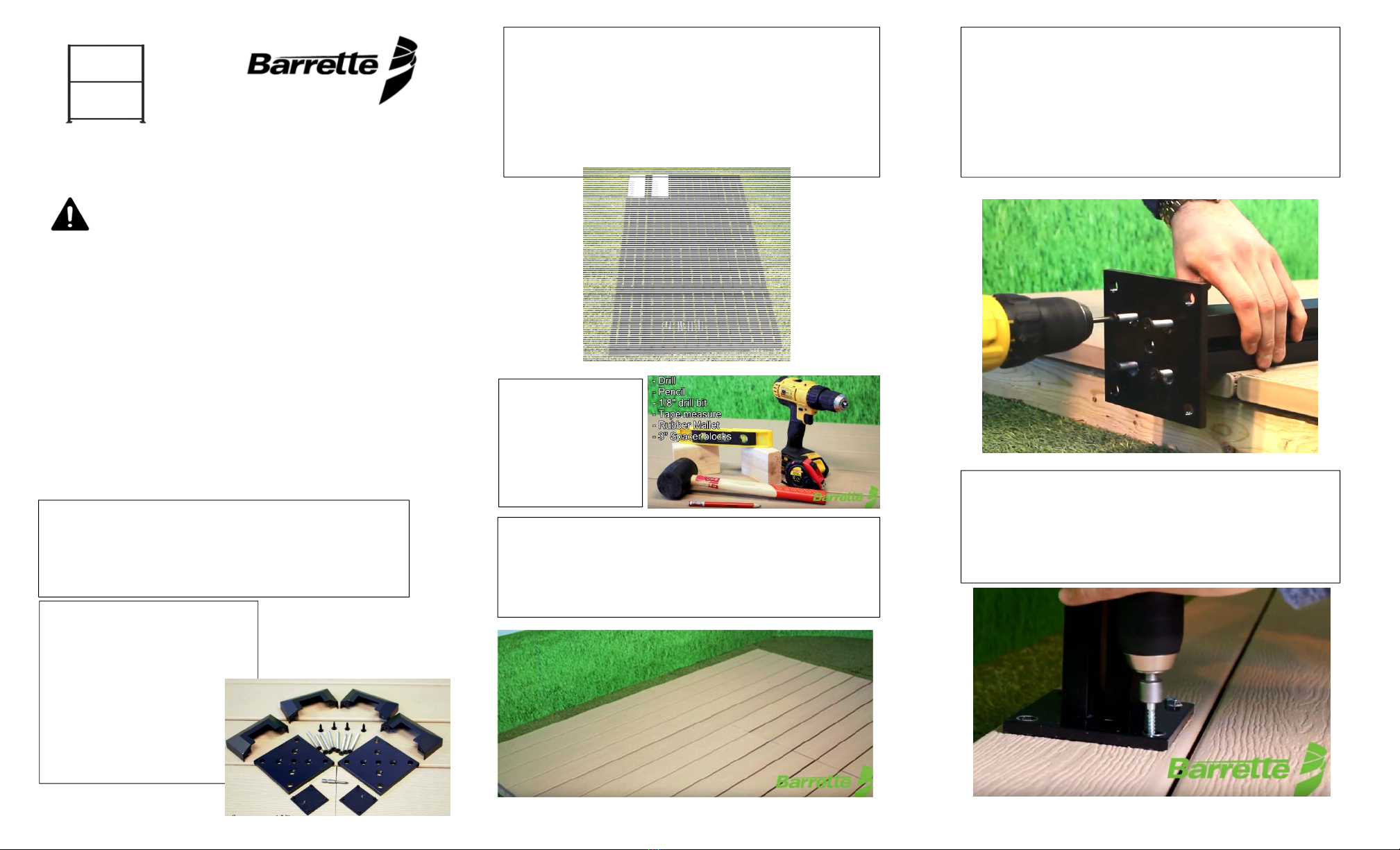
Étape4:
Placerlesdeuxblocsd'espacementde3poafindesupporterla
traverseinférieure.Prendrelatraverseinférieure,laglisserdansla
rainuredupremierpoteauetladéposersurlesblocs
d'espacements.Remarque:cetteétapesertàdéfinirladistance
entreles
oteaux.
Étape5:
Prendreledeuxièmepoteauetyinsérerleboutopposédela
traverseinférieure.S'assurerquelatraverseestcomplètement
inséréedanslepoteau.Verrouillerledeuxièmepoteauenplaceen
répétantl'étape3.
Avis:Sivousdésirezconnecterd’autresjeuxdestructureau
cadreprincipal,desjeuxd’extensiondestructuredeligneoude
coinsontdisponibles(vendusséparément).
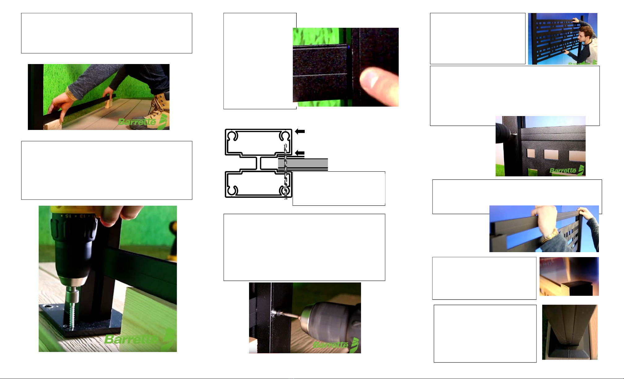
Étape6 :
Vérifierl’emplacementpourle
pré‐perçagedutrouautravers
dupoteauetdelatraversetel
quemontréci‐dessous.Les
trouspilotesdevraientêtre
localisésdirectementsur
l’intersectiondelapetite
rainuredupoteauetcelledela
traverseenprenantsoindene
pastranspercerlafaceopposée
du
oteau.
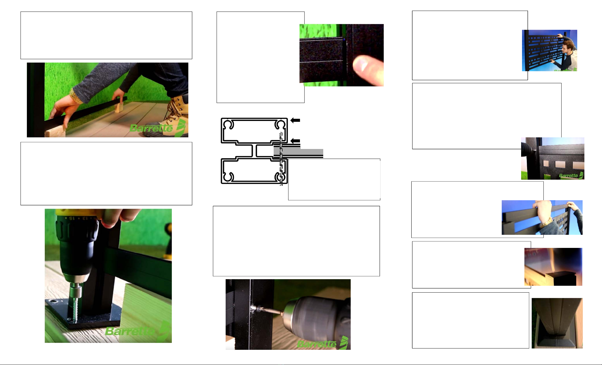
Étape7:
Unefoisquelesvissontbienfixéesdansles
deuxpoteaux,faireglisserlepanneau
décoratifentrelespoteauxdansles
rainuresduhautjusqu'àcequ'ilrepose
danslamoulureinférieureenU.
Conseil:S'assurerquelespanneauxsont
placésdansladirectiondésiréeavantle
monta
e.
Étape6‐ suite:
Àl’aideduforet1/8’’fourni,pré‐percerletroupilotetel
qu’indiqué.
Lavisdevraitêtreinstalléedirectementsurlapetiterainuredu
poteauetdelatraverse.
Àl'aidedel'emboutdetournevisàtêtecarrée#2fournidans
l'ensemble,insérerlavisdanslesdeuxpoteaux,verrouillantles
poteauxetlestraversesensemble.
Retirerlesblocsd’espacement.
Étape8:
GlisserlamoulureenHdanslarainureàpartirduhaut,
ladéposantsurledessusdupanneaudécoratif.Soulever
lamoulureenHde1/8popourpermettrel'expansionet
lacontraction,puispré‐perceruntrouensuivantle
mêmeprocédéqu’àl’étape6.Lavisdoitêtreinstallée
directementsurlapetiterainuredupoteau,enraccord
aveclamoulureenH.
Étape11 :
Assemblerl'anneaudécoratifsurlaplaque.
Prendreuncôtédel'anneauetenfoncerles
bouchonsdanslestroussituésendessous.
Prendreladeuxièmemoitiédel'anneauet
pousserensemble.Glissersurlaplaque
pouruneapparencefinie.
VousDEVEZpré‐percerautraversde
cettesurface.
Poteaudefinmontré.S’assurerde
nepastranspercerlafaceopposée
dupoteau.
VousDEVEZpré‐percerautraversdela
facedupoteau,desdeuxcôtésdela
traverseetdumurintérieurdupoteautel
quemontré.Lemanquementàcette
obligationcauseradesproblèmespendant
l’installation.
Étape9:
Répéterlesétapes7et8pourlepanneauduhaut.
Remarque:Toujoursutiliserun
rubanàmesurerpourvérifierque
lestraversessontàégaledistance
l'unedel'autreetqu'ellessontde
niveau.
Étape10:
Placerlescapuchonssurlespoteauxen
alignantleslanguettessouslestrousdu
poteau.Àl'aided'unmailletencaoutchouc,
poussercomplètementlecapuchonsurle
oteau.