BARSTOW 20519 User manual

9139 • 112415
52” BARSTOW
CEILING FAN
Owner’s Manual
Models #20519
Turn of the CenturyTM
1
If a problem cannot be remedied or you are experiencing diculty with installation,
please contact the Service Department: 1-877-459-3267, 9 a.m.- 5 p.m. Central time.
TM
Turn of the Century
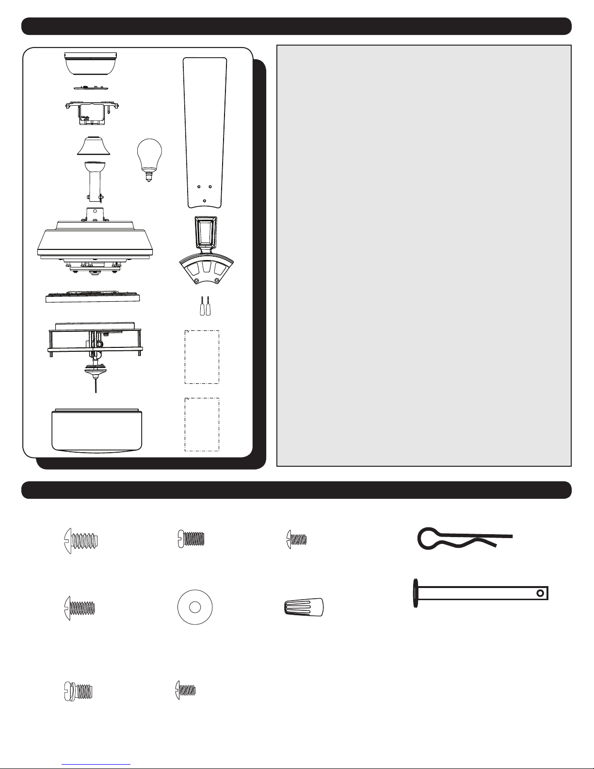
PACKAGE CONTENTS
2
HARDWARE CONTENTS
19
20
21
22 25
24
23 26 28
27
1. Canopy
2. Canopy Cover
3. Mounting Bracket
4. Yoke Cover
5. Downrod
6. Motor Assembly
7. Fitter Plate
8. Light Pan
9. Light Kit
10. Finial Cap
11. Finial
12. Glass Bowl
13. Bulb (x 3)
14. Blade (x 5)
15. Blade Arm (x 5)
16. Pull Chain Extension (x 2)
17. Hardware Kit
18. Owner’s Manual
19. Mounting Bracket
Screw (x 4)
20. Blade Screw (x 15)
21. Closemount Screw (x 3)
22. Downrod Set Screw (x 2)
23. Blade Washer (x 15)
24. Fitter Plate Screw (x 3)
25. Light Pan Screw (x 3)
26. Wire Connector (x 3)
27. Downrod Clip
28. Downrod Pin
Unpack your fan and check the contents. You should
have the following items:
PACKAGE CONTENTS
HARDWARE CONTENTS
Note: Some extra hardware has been included. The quantity
listed above is the number required for installation.
Hardware Kit
Owner’s
Manual
1
2
3
4
5
6
7
8
9
10 11
12
13 14
15
16
17
18

TM
Turn of the Century
MOUNTING OPTIONS
3
Closemount
Downrod Mount
Angled Ceiling Mount (Up to 16 degrees)
A. 17.89 in. B. 12.41 in. C. 10.67 in. D. 11.06 in. E. 5.08 in.
DIMENSION REFERENCE
C
D
A
B
Choose one of the following mounting options:
Closemount Installation is best suited for ceilings lower than 8 feet. It does not utilize the downrod.
Downrod Mount is best suited for ceilings 8 ft. or higher. For taller ceilings you may want to use a longer downrod
(not included).
Angled Ceiling Mount is best suited for angled or vaulted ceilings. A longer downrod is sometimes necessary to
ensure proper blade clearance from the ceiling. If using the angle mount, check to ensure the ceiling angle is not
steeper than 16 °.

TM
Turn of the Century
WARNING
READ ALL SAFETY INFORMATION AND INSTALLATION INSTRUCTIONS BEFORE YOU BEGIN INSTALLING THE
FAN AND SAVE INSTRUCTIONS.
Check set screws and re-tighten where necessary before installation.
To reduce the risk of personal injury, do not bend the blade arms when installing the blade arms, balancing
the blades or cleaning fan. Do not insert foreign objects in between rotating fan blades.
Before changing the fan direction, turn o the fan and wait for the fan blades to stop completely.
NOTE: The safeguards provided by these safety instructions and by the separate installation instructions
are not meant to cover all possible conditions and situations that may occur. It must be understood that
common sense, caution and care are factors which can not be built into this product. These factors must be
supplied by the person(s) installing, caring for and operating the fan.
TO AVOID RISK OF ELECTRIC SHOCK, BE SURE TO SHUT OFF POWER AT THE MAIN FUSE OR CIRCUIT
BREAKER BOX BEFORE INSTALLING OR SERVICING THIS FIXTURE. TURNING OFF THE ELECTRICAL POWER
BY USING THE LIGHT SWITCH IS NOT SUFFICIENT TO PREVENT ELECTRICAL SHOCK.
TO REDUCE THE RISK OF INJURY, INSTALL THE FAN SO THAT THE BLADES ARE AT LEAST 7 FEET (2.1
METERS) ABOVE THE FLOOR AND AT LEAST 30 INCHES (0.5 METERS) FROM THE TIP OF THE BLADES TO
THE WALL.
TO REDUCE THE RISK OF FIRE, ELECTRIC SHOCK, OR PERSONAL INJURY, MOUNT TO OUTLET BOX MARKED
“ACCEPTABLE FOR FAN SUPPORT” AND USE MOUNTING SCREWS PROVIDED WITH THE OUTLET BOX.
THE INSTALLATION HAS TO BE IN ACCORDANCE WITH THE NATIONAL ELECTRICAL CODE, ANSI/NFPA
70-1999 AND LOCAL CODES. IF YOU ARE UNFAMILIAR WITH THE METHODS OF INSTALLING ELECTRICAL
WIRING, SEEK THE SERVICES OF A QUALIFIED LICENSED ELECTRICIAN.
SAFETY INSTRUCTIONS
IMPORTANT:
Before you begin installing or using the fan, carefully read the entire manual. If unsure about any part of the
installation, contact a qualied electrician.
Save all instructions.
NOTE: The fan weight is Net Weight: 16.9 lb (7.68 kg). Be sure the outlet box (not included) is securely attached
to the building structure and is marked “Acceptable For Fan Support”. Failure to do so may cause the fan to fall,
which could result in serious injury or death.
4
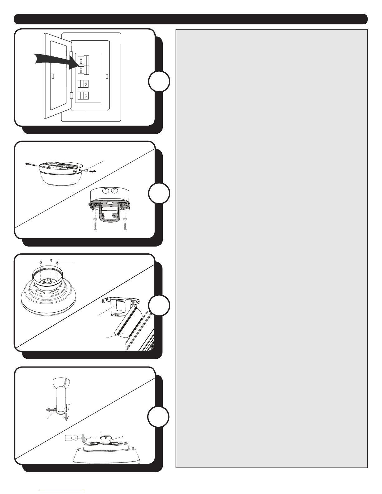
Turn of the CenturyTM
Downrod
Clip
Set Screw
Yoke
Downrod
Pin
5
ASSEMBLY INSTRUCTIONS
2
1
1. Turn OFF the electrical power at the main fuse or circuit
breaker.
2. Loosen all four mounting bracket screws and
completely remove the two mounting bracket screws
from the round holes in the canopy. Save screws for later
use. Secure the mounting bracket to the outlet box (not
included) using the screws and washers provided with
the outlet box.
Warning: To reduce the risk of re electric shock,
or personal injury, mount to the outlet box marked
“acceptable for fan support” and use the mounting
screws and washers provided with the outlet box.
4
3. CLOSEMOUNT INSTALLATION (OPTIONAL)
a. Remove the canopy cover from the bottom of the
canopy.
b. Remove the three Phillips-head closemount screws from
the top of the motor assembly.
c. Align the holes in the bottom of the canopy with the
screw holes in the top of the motor assembly. The larger
holes in the canopy will encompass the three pre-installed
screws.
d. Secure the canopy to the top of the motor with the
closemount screws that were previously removed.
e. Hang the fan on the hook of the mounting bracket to
free hands during wiring process.
Proceed to Step 9.
Closemount
Screw
Canopy
Mounting
Bracket
Mounting
Bracket Screw
3
4. DOWNROD MOUNT - Remove the downrod clip and
downrod pin from the downrod. Then, loosen but don’t
remove the two set screws in the yoke.

6Turn of the CenturyTM
8 in.
ASSEMBLY INSTRUCTIONS
7
5
6
5. Feed the wires coming from the yoke through the yoke
cover, canopy and out through the top of the downrod.
7. Depending on the length of the downrod, you
may choose to shorten the lead wires to simplify
wiring. If so, measure 8 inches of lead wire extending
from the top of the downrod, then use wire cutters (not
included) to remove the excess wire. Strip 1/2 in. from the
end of the shortened wires.
6. Insert the downrod into the yoke and reinstall the
downrod pin and downrod clip. Then re-tighten the two
set screws.
8. Lift the downrod into the mounting bracket. Rotate the
downrod until the tab in the mounting bracket is seated in
the slot in the downrod ball.
WARNING: The fan and/or downrod should not rotate in
the mounting bracket if installed correctly. Failure to align
the slot in the downrod ball with the tab on the mounting
bracket may result in fan falling, causing serious injury or
death.
Downrod
Yoke Cover
Canopy
Downrod Pin
Yoke
Downrod
Downrod Clip Set Screw
Yoke
Tab
Slot
Downrod
Mounting
Bracket
8
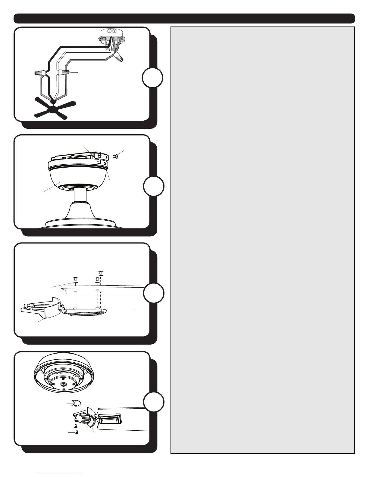
7Turn of the CenturyTM
Black (Hot)
White (Neutral)
Bare/Green (Ground)
Black
Blue
White
Green
Blade Screw
Blade
Washer
Blade Arm
Blade
ASSEMBLY INSTRUCTIONS
11
10. Raise the canopy, ensure the two loosened mounting
bracket screws are aligned with the J-shaped slots in
the canopy. Then turn the canopy clockwise until the
mounting bracket screws are completely engaged in
the J-shaped slots. Install the two previously removed
mounting bracket screws in the round holes. Securely
tighten all four mounting bracket screws.
10
9
Canopy
Round
Hole
Wire Connector
Mounting
Bracket Screw
J-shaped Slot
11. Partially insert three blade screws, along with the
blade washers, through the blade and into the blade arm.
Tighten each blade screw, starting with the one in the
middle. Repeat this step for the remaining blades and
blade arms.
12
12. Remove the ten motor screws from the underside
of the motor assembly. Secure the blade arms to the
underside of the motor using motor screws. Secure each
blade arm to motor before moving to the next.
9. Use wire connectors to connect the fan wires to the
power supply wires according to the wiring diagram and
the following instructions:
• Connect the white wire from the fan to the white (neutral)
supply wire.
• Connect the black and blue wires from the fan to the
black (hot) supply wire.
• Connect the green wire from the mounting bracket to the
bare/green (ground) supply wire.
Note: If there is a second hot/power supply wire coming
from the outlet box, connect it to the blue (light power) fan
wire for separate light and fan control.
Important: After the connections have been made, the
wires should be turned upward and pushed carefully
up into the outlet box. Place the black and white wire
connections on opposite sides of the outlet box.
Blade Arm
Motor Screw
Blade Isolator

8Turn of the CenturyTM
ASSEMBLY INSTRUCTIONS
15
14. Remove one light pan screw and its washer from
the light pan and loosen but do not remove the other
two screws. Then, connect the 9-pin from the fan to the
9-pin connector from the light kit. Lift the light kit up
and align the two key hole slots in the light kit with the
previously loosened light pan screws. Turn the light kit in
a clockwise direction. Re-install the previously removed
light pan screw and its washer. Then, tighten all three
screws securely.
13. Remove one tter plate screw and its washer from
the tter plate and loosen, but do not remove the other
three. Feed the 9-pin connector through the center hole
in the light pan. Then, align the two key hole slots in the
light pan with the previously loosened tter plate screws.
Turn the light pan in a counterclockwise direction.
Re-install the previously removed tter plate screw and
tighten all three screws securely.
14
13
15. Remove the nial cap and nial from the threaded
rod at the bottom of the light kit. Then, install the
candelabra-base bulbs in the sockets of the light kit.
16. Feed the pull chains through the holes in the glass
bowl and then lift the center hole in the glass bowl over
the threaded rod on the light kit. Then, place the nial cap
over the threaded rod and secure with nial.
16
Finial Cap
Finial Cap
Light Kit
9-pin
Connector
9-pin
Connector
Light Pan
Screw
Fitter Plate
Screw
Washer
Washer
Glass Bowl
Finial
Finial
Bulb

9Turn of the CenturyTM
ASSEMBLY INSTRUCTIONS
17
17. Attach the pull chain extensions to the pull chains.
OPERATING INSTRUCTIONS
1. Using a ceiling fan will allow you to raise your
thermostat setting in summer and lower your thermostat
setting in winter without feeling a dierence in your
comfort. To access the reverse switch, located on the light
kit, the glass bowl must be removed.
Note: Wait for the fan to stop before moving the reverse
switch.
In warmer weather, push the reverse switch left which
will result in downward airow creating a wind chill eect.
In cooler weather, push the reverse switch right which
will result in upward airow that can help move stagnant,
hot air o the ceiling area.
2. The fan pull chain has four positions to control fan
speed. One pull is HIGH, two is MEDIUM, three is LOW
and four turns the fan OFF.
The light pull chain has two positions to control the light,
ON and OFF.
Reverse Switch 1
2
Light Pull Chain
Reverse Switch
Pull Chain Extension
Fan Pull Chain

TM
Turn of the Century
10
If you have diculty operating your new ceiling fan, it may be the result of incorrect assembly, installation or
wiring. In some cases, these installation errors may be mistaken for defects. If you experience any faults, please
check the Troubleshooting section below. If a problem cannot be remedied or you are experiencing diculty in
installation, please contact the Service Department: 1-877-459-3267, 9 a.m.- 5 p.m. Central time.
PROBLEM SUGGESTED REMEDY
1. Fan does not start 1. Turn on wall switch, and check fuses or circuit breakers.
2. Check power supply wire connections to fan and switch wire connections in switch
housing.
CAUTION: Make sure main power is turned o before entering canopy.
3. Make sure forward/reverse switch pushed completely up or down. Fan will not
operate when switch is in the middle.
4. Make sure that the wall switch is turned ON.
1. Make sure all screws in motor housing are snug, but not overtightened.
2. Make sure the motor screws which attach the blade arm to the motor are tight.
3. Make sure wire connectors in switch housing are not rattling against each other or
against the interior wall of the switch housing.
CAUTION: Make sure main power is turned o before entering switch housing.
4. Using a full-range dimmer to control fan speed will cause humming noise from
the fan. To reduce risk of re or electrical shock, do NOT use a full range dimmer to
control fan.
1. Ensure all blades are screwed rmly into blade arms.
2. Ensure all blade arms are tightened securely to motor.
3. Ensure canopy and mounting bracket are tightened securely to outlet box and
outlet box is mounted rmly to ceiling joist.
4. Switch one blade with a blade from the opposite side. Or balance the fan using the
balancing kit.
5. If blade wobble is still noticeable, interchanging two adjacent (side by side) blades
can redistribute the weight and possibly result in smoother operation.
1. Ensure the 9-pin connector from the fan is securely connected to the 9-pin
connector from the light kit.
2. Check for loose or disconnected wires in fan switch housing.
3. Check for loose or disconnected wires in light kit.
4. Check for faulty light bulbs.
CAUTION: Make sure main power is turned o before entering switch housing.
2. Fan is noisy
3. Fan wobbles
4. Light does not work
TROUBLESHOOTING

TM
Turn of the Century
LIMITED LIFETIME WARRANTY
To obtain Service, please contact the Service Department:
1-877-459-3267, 9 a.m.- 5 p.m. central time.
Model Name: 52” Barstow Ceiling Fan
Model No: 20519 - Oil Rubbed Bronze (SKU: 355-7053)
The limited lifetime warranty covers this ceiling fan, for residential use by the original purchaser, against
defects in material or workmanship as follows:
If your Turn of the Century Ceiling Fan motor fails at any time during the lifetime of the original purchaser
due to defects in material or workmanship, we will provide a replacement part free of charge.
If your fan motor fails at any time within one year after the original date of sale to the original purchaser
due to defects in material or workmanship, we will provide labor to repair the defect, with the exception
of take down/reinstallation, free of charge. The original purchaser will be responsible for all labor costs
after this one year period.
If no replacement parts are provided for any part of your fan motor that fails at any time during your
lifetime due to defects in material or workmanship, we will refund the original purchase price of your fan.
If your fan blades, pull chain switch, reverse switch, or any accessory, except glass globes and light
bulbs, fails at any time within one year after the original date of purchase due to a defect in material and
workmanship, we will repair or, if we choose, replace the defective blades, switch, or accessory free of
charge, with the exception of take down/reinstallation services.
If the original purchaser ceases to own the fan, this warranty and any implied warranty, including but not
limited to any implied warranty of merchantability or tness for a particular purpose, become void. This
warranty and any implied warranty, including but not limited to any implied warranty of merchantability
or tness for a particular purpose, do not cover glass globes, light bulbs, or nish on any metal portions
of the fan.
This warranty is in lieu of express warranties. The duration of any implied warranty of merchantability or
tness for a particular purpose, with respect to any Turn of Century Ceiling Fan motor, blades, switch,
or accessories, is expressly limited to the period of the express warranty set forth above for such motor,
blades, switch, or accessories.
This warranty excludes defects, malfunctions, or failures of any Turn of Century Fan that are caused by
repairs by persons not authorized by us, use of parts or accessories not authorized by us, mishandling,
improper installation, modications or damage to the fan while in your possession, or unreasonable use,
including failure to provide necessary maintenance.
To obtain service, contact the service department. You will be responsible for all insurance and freight or
other transportation charges to our factory or service center. A copy of sales receipt is required in order
to obtain service. We will return your fan freight prepaid. Your fan should be properly packed to avoid
damage in transit, for we will not be responsible for any such damages.
In no event shall Turn of Century Fan be liable for consequential or incidental damages.
Some states do not allow the exclusion or limitation of consequential or incidental damages, in which
case the above limitation or exclusion may not apply.
This warranty gives you specic legal rights and you may also have other rights which vary from state
to state.
11
Table of contents
Popular Fan manuals by other brands

Soltronics
Soltronics LTG-CF5002 Installation instruction

Fandis
Fandis GF Series Mounting instructions

Monte Carlo Fan Company
Monte Carlo Fan Company 5FWR52XXD Series installation instructions

Craftmade
Craftmade Leeward LW52 installation guide

Bosch
Bosch DHI62 Series operating instructions

J&D MAnufacturing
J&D MAnufacturing BARNSTORMER quick start guide


Munters
Munters EM52 Assembly manual

Modine Manufacturing
Modine Manufacturing Atherion MPR INSTALLATION AND SERVICE MANUAL SUPPLEMENT

Humhold
Humhold HDFSD -A01 owner's manual

Honeywell
Honeywell PERFECT WINDOW HR150 Product data

Kampmann
Kampmann WZA Assembly instructions

Fakir
Fakir VC 40 S Prestige operating instructions