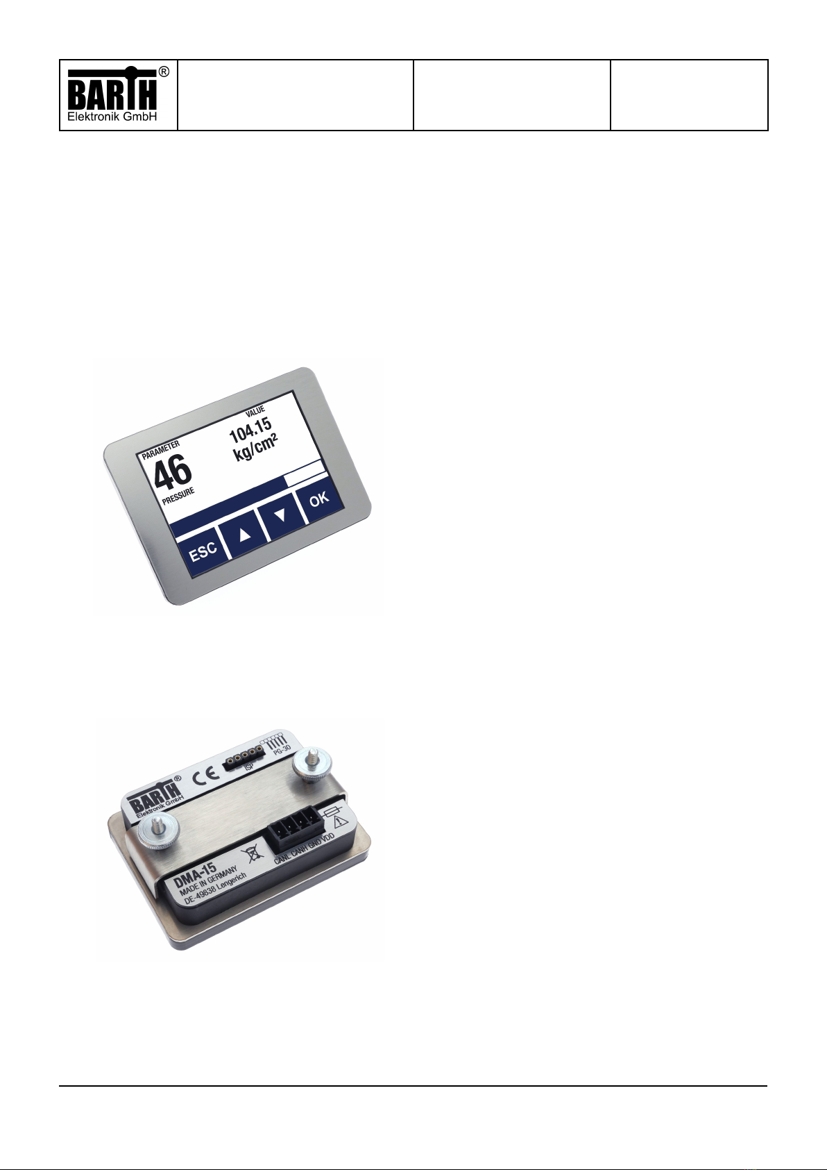
CAN Display lococube
DMA-15
MANUAL
Page/of:
Document:
Date:
4/23
9021-0028-D
11.12.2023
© 2023 BARTH Elektronik GmbH | Im Depot 1-3 | D-49838
engerich | www.barth-elektronik.de |
[email protected]® BARTH and lococube are registered trademarks of BARTH Elektronik GmbH. All rights reserved to make changes without prior notice.
3Requirements for Operation
To operate the DMA-15 CAN display you ill need the
follo ing items:
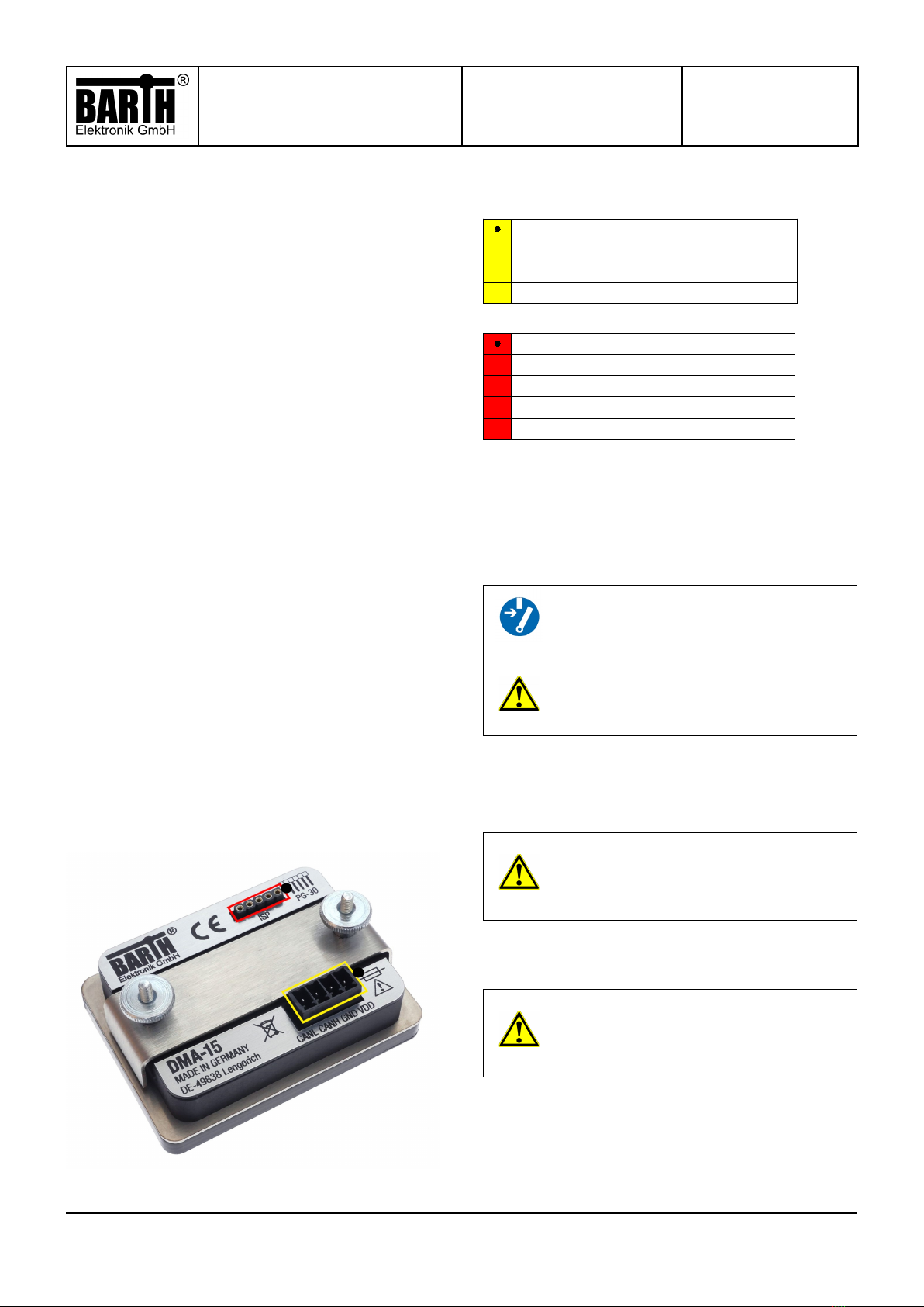
1. The lococube® CAN Display DMA-15.
2. A mini-PLC ith a CAN interface (the lococube®
STG-800 is a good choice to get started and ill be
used in all our upcoming examples:
lococube® mini-SPS STG-800
3. A VK-16 cable is needed to connect the mini-PLC to
your computer:
Verbindungskabel VK-1 6
4. A cable to connect the CAN-Bus of the mini-PLC to the
one of the DMA-15. A KS-85 wiring harness, hich has
those connections already included can be found here:
Wiring harness KS-85
5. A resistor of 60Ω needs to be placed bet een the
CANH and the CANL connector of the DMA-15 and the mi-
ni-PLC. (You can omit this step if you‘re using a KS-85
wiring harness since it already includes those resistances).
6. A po er adapter to po er the mini-PLC and the
DMA-15 that supplies a voltage bet een 7 - 32 VCD.
(If you‘re using a KS-85 wiring harness you can plug in a
hollo plug ith these dimensions: Ø 5,5 mm / 2,1 mm).
7. A computer ith a Windo s operating system installed.
8. The miCon-L soft are hich can be do nloaded here:
miCon-L
9. The template programs hich can be do nloaded here:
Template Programs
4 Operation with miCon-L
4.1 Connecting the mini-PLC
Connect the mini-PLC to your computer. We‘ll be
using the loco-cube® STG-800. Plug the USB
connector of the VK-16 cable into your computer and plug
the other end into the mini-PLC into the TTL232 slot.
The orientation of the connector matters! Please orient the
connector, ith the little bump, facing left, as sho n belo .
Connect the CANH terminal of the mini-PLC to the CANH
terminal of the DMA-15 and connect the CANL terminal
of the mini-PLC to the CANL terminal of the DMA-15.
If you are using our KS-85 wiring harness, this can be
done simply by plugging the X1 connector into the mini-
PLC and the X2 connector into the DMA-15 or vice versa. If
you are not using a KS-85 wiring harness, make sure to
put a resistor of 60Ω bet een the CAN terminals! Plug in
the po er adapter and po er the mini-PLC
and the DMA-15.
1.4 Using miCon-L
Do nload and install the miCon-L soft are on your
computer. Do nload the template programs for the
DMA-15 here and place them at a location of your chosing:
After the STG-800 and the DMA-15 have been properly
ired up and connected, start the miCon-L soft are.
It‘s vital that you choose the correct serial port before you
continue into the actual programming environment!
No use the „folder icon“ in the top left hand corner to na-
vigate to the folder you have placed the template projects
in.
Navigate to the location you chose to put the template fol-
der in and open one of the projects using the .MDL le.
After you have succesfully opened the project of your
choice, there is one additional step that you must al ays
do hen creating or opening a ne project!
Go to Extras -> COM-Port Parameter.