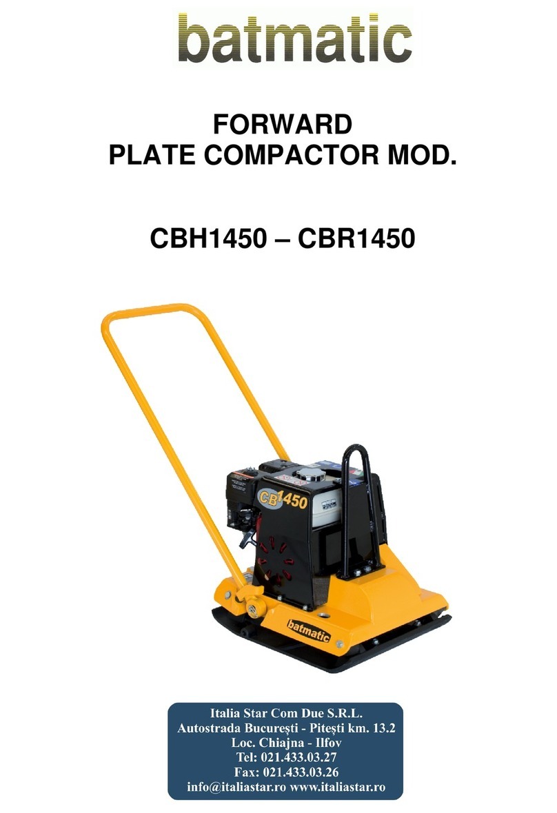
Batmatic CR5560 User manual

CR5560 / CR5570 / CR5585
PLATE COMPACTOR

CR5560 / CR5570 / CR5585 R02
- 2 -

CR5560 / CR5570 / CR5585 R02
FOREWORD
We thank You to have chosen a Batmatic plate
compactor. Your ne machine is a useful and safety
job’s tool.
Observing the safety regulations and the instructions
in this book, there ill not be any physical injury and
the plate ill be al ays in good condition.
Worn-out machine parts have to be replaced as soon
as possible. You could find the code numbers to
order the spare parts in the chapter “Exploded
Vie s” in this instruction book.
- 3 -

CR5560 / CR5570 / CR5585 R02
TABLE OF CONTENTS
SAFETY INSTRUCTIONS FOR PLATE COMPACTORS................................................................5
GENERAL INSTRUCTIONS........................................................................................................................ 5
OPERATION................................................................................................................................................ 5
SAFETY....................................................................................................................................................... 5
TRANSPORT............................................................................................................................................... 6
MAINTENANCE........................................................................................................................................... 6
PERIODIC MAINTENANCE......................................................................................................................... 6
TECHNICAL DATA..........................................................................................................................7
SOUND MEASUREMENTS......................................................................................................................... 7
VIBRATION MEASUREMENTS................................................................................................................... 7
DIMENSIONS............................................................................................................................................... 8
CLIMBING ABILITY.........................................................................................................................9
FUNCTION....................................................................................................................................... 9
OPERATION.................................................................................................................................. 10
TO CHECK BEFORE STARTING..............................................................................................................10
ENGINE STARTING (MANUAL)................................................................................................................ 10
ENGINE STOPPING (MANUAL)................................................................................................................ 10
ENGINE STARTING (ELECTRIC STARTER)............................................................................................10
ENGINE STOPPING (ELECTRIC STARTER)........................................................................................... 10
ENGINE OIL............................................................................................................................................... 11
AIR FILTER (DRY)..................................................................................................................................... 11
AIR FILTER (OIL BATH)............................................................................................................................ 11
HYDRAULIC PUMP................................................................................................................................... 11
LUBRIFICANTS......................................................................................................................................... 12
ENGINE / EXCITER REVS........................................................................................................................ 12
MAINTENANCE.............................................................................................................................13
TROUBLESHOOTING...................................................................................................................1
EXPLODED VIEWS....................................................................................................................... 15
WARRANTY..................................................................................................................................30
EC DECLARATION OF CONFORMITY.........................................................................................31
- 4 -

CR5560 / CR5570 / CR5585 R02
SAFETY INSTRUCTIONS FOR PLATE COMPACTORS
GENERAL INSTRUCTIONS
1. Plate compactors must only be operated by person ho:
is at least 18 years old;
is physically and mentally fit for this job;
may be expected to carry out the job he’s charged ith carefully.
The employer must directly assign people ho guide plate compactor.
2. Plate compactors must only be used for compaction jobs observing safety and operating
instructions.
3. People ho ork ith plate compactors must kno everything regarding safety
instructions.
4. Al ays ear appropriate protective clothes (ear protections, gloves, protecting shoes and
helmet).
OPERATION
1. When You use recoil starter it is important to stand in a proper position near to the engine
and to hold tight the handle.
WARNING
Pull hand crank until it starts, in order to avoid counterblows.
2. Do not alterate the operation devices of the plate compactor.
3. Do not leave control elements during compaction.
4. Store the compactor in a safe place out of the reach of children.
5. Al ays refill fuel tank hen the engine is stopped. Do not allo fuel to come into contact
ith the hot parts of the compactor.
6. Do not smoke near the machine. Do not run the engine near open flames.
7. Al ays check fuel tank cap. If there is a fuel cock, shut it off hen the machine is stopped.
WARNING
If fuel tank leaks, replace it immediately: Do not run the machine if fuel tank
leaks.
8. Do not use the compactor in places here there are gaseous exhalations.
9. Do not use the machine indoors or in an enclosed area unless inadequate ventilation.
10. Al ays ear appropriate protective clothes.
11. When the ork area is near slopes, the compactor could turn over.
12. When you use compactor in reverse and in a narro place, the operator must be
side ays from the handle in order to avoid stumbling.
13. Al ays operate in safe conditions in order to avoid accidents.
14. Al ays operate in maximum stability conditions.
15. Use transport heels only for movements in yard. In all the other situations are to be
removed.
SAFETY
1. Plate compactors have to be used observing all safety regulations.
2. Al ays check all controls and safety devices.
3. If there are any problems, stop immediately the machine and inform the person
responsible of the yard.
- 5 -

CR5560 / CR5570 / CR5585 R02
TRANSPORT
1. For loading and unloading the compactor appropriate lifting-gear are necessary hich
have to be used on the lifting points.
2. Be sure that the ramps are fixed and check the tolerable eight in order to avoid
turnovers.
3. Tie the machine on vehicle to prevent sliding or tipping over.
4. For long transports, empty the fuel tank and close it completely.
WARNING
Do not lift or hook the plate compactor by the handle.
MAINTENANCE
1. Use only original spare parts.
2. Do not alterate the operation devices of the plate compactor.
3. Do not change the engine rpm.
WARNING
Modifications in this machine are subject to the express approval of Batmatic
hich in case of non observance ill refuse all liabilities.
4. Check the compactor hen the engine is s itched off.
5. As soon as maintenance and repair jobs have been completed, all safety devices have to
be properly reinstalled.
PERIODIC MAINTENANCE
Regular maintenance is required for a good performance of the compactor.
Please also observe regulations valid in Your yard.
- 6 -

CR5560 / CR5570 / CR5585 R02
TECHNICAL DATA
Item CR5560 CR5570 CR5585
Operating eight 400 kg
Size of base plate (W x L) 600 x 955 mm 700 x 955 mm 850 x 955 mm
Frequency 70 Hz
Po er transmission
Centrifugal force
Centrifugal clutch - Belt
55 kN
Engine
BH39 DL DH 0 DH50
Honda
GX 390
Lombardini
15LD440
Hatz
1 B40
Hatz
1 D50
Displacement 389 cm3441 cm3462 cm3517 cm3
Max Po er 9,6 kW
13,0 Hp
8,1 kW
11,0 Hp
7,4 kW
10,0 Hp
7,9 kW
10,7 Hp
Fuel Petrol Diesel Diesel Diesel
Travel speed 25 m/min
SOUND MEASUREMENTS
The product has been produced in accordance ith the standard 2000/14/CE, procedure I annex
VI.
Measured sound po er level 106 [dB(A)] and guaranteed sound po er level 108 [dB(A)] on a
significant equipment.
VIBRATION MEASUREMENTS
Products are tested for hand/arm vibration level in accordance ith annex D prEN500-4:2001
The hand/harm vibration level is ,5 m/s2
The plate compactor has been tested on a “macadam” surface, produced ith not cleaned stone
crusher grit, ith 16 mm medium diameter ( ith components hich have diameter that goes from
10 to 20 mm).
- 7 -

CR5560 / CR5570 / CR5585 R02
DIMENSIONS
- 8 -

CR5560 / CR5570 / CR5585 R02
CLIMBING ABILITY
FUNCTION
The vibration required for tamping is produced by the exciter hich is on the compacting plate.
The engine starts the exciter and the torque is transmitted by the centrifugal clutch and by the belt.
In order to allo the idling of the drive engine, the centrifugal clutch, at lo engine speeds,
interrupts the flo of po er to exciter. The compactor must al ays be used ith the gas handle in
the operative position.
The engine supporting and the compacting plates are connected by 4 shockmount, hich are
mounted to avoid that vibrations reach the operator.
Plate compactor is equipped ith hydraulic system that allo s to change gradually the for arding
speed.
The direction of plate compactor depends on the position of control levers on the handle.
- 9 -

CR5560 / CR5570 / CR5585 R02
OPERATION
TO CHECK BEFORE STARTING
1. Engine oil level
Check oil level using the proper dipstick. If it is necessary refill ith SAE 15 W 40 oil.
2. Air filter
Check if air filter is clean and in good condition. If it is necessary clean or replace it.
3. Fuel
Never use oil/gasoline mixture or dirty fuel. Avoid getting dirt, dust or ater into fuel tank.
Refuel avoiding leaks on engine.
ENGINE STARTING (MANUAL)
1. Open the fuel valve.
2. Move the throttle lever to 3/4 position.
3. Turn the choke lever (if present).
4. Turn the engine s itch on the ON position.
5. Pull the starter grip lightly until resistance is felt, then pull briskly.
6. As the engine arms up, gradually move the choke lever (if present).
7. Warm up the engine at the minimum speed for some minutes.
8. The compactor ill begin to move hen the throttle lever ill be in operative position.
ENGINE STOPPING (MANUAL)
1. Move the throttle lever to the minimum position. Let the engine turn at the minimum speed
for some minutes.
2. Turn the engine s itch on the OFF position.
WARNING
Never operate the engine switch when the engine is at the ma imum speed.
3. Turn the fuel valve to the OFF position.
ENGINE STARTING (ELECTRIC STARTER)
1. Insert the key into the dashboard.
2. Turn the key on the ON position and after on the START position until the engine starts.
ENGINE STOPPING (ELECTRIC STARTER)
1. Move the throttle lever to the minimum position. Let the engine turn at the minimum speed
for some minutes.
2. Turn the key on the OFF position.
WARNING
Never operate the engine switch when the engine is at the ma imum speed.
3. Turn the fuel valve to the OFF position.
- 10 -

CR5560 / CR5570 / CR5585 R02
ENGINE OIL
1. Check oil level using the proper dipstick, if necessary refill ith SAE 15 W 40 oil.
Oil change
1. Drain oil at arm engine.
2. Refill ith SAE 15W40 oil.
WARNING
Only use oil with characteristics advised to the manufacturer engine (see
engine book).
AIR FILTER (DRY)
Regularly clean the air filter in order to avoid carburettor damages especially hen
operating in dusty areas.
1. Open air cleaner and remove element.
2. Lightly and repeatedly tap the element on a hard surface to eliminate all excess dirt.
3. Clean the element.
4. Refit the air filter. Do not run the engine ithout the air filter.
AIR FILTER (OIL BATH)
Regularly clean the air filter in order to avoid carburettor damages especially hen
operating in dusty areas.
1. Open air cleaner and remove upper element.
2. Wash the upper filtering element ith soap and ater.
3. Clean the upper bo l.
4. Remount the upper filtering element.
5. Remove the lo er filtering element.
6. Clean and dry filtering element.
7. Drain and clean bo l.
8. Fill ith engine oil up to level mark.
9. Reassemble air cleaner.
WARNING
Never use gasoline or low flash point solvents for cleaning the air filter to
avoid fire and e plosions.
HYDRAULIC PUMP
1. Set handle in horizontal position.
2. Open handle cover.
3. Take off the pump cap
4. Check oil level, refill if it is necessary until it goes out.
5. Close the pump
6. Move the control levers repeatedly in order to let the air go out.
Repeat point 3 to 6 until there is no air in the pump
- 11 -

CR5560 / CR5570 / CR5585 R02
LUBRIFICANTS
Modello Quantità Tipo
Exciter CR 55 0,80 kg Pontonic FDL
75W90
Pump CR 55 0,20 kg T68
Engine All models See engine
instructions SAE 15W40
ENGINE / EXCITER REVS
MODEL ENGINE EXCITER
CR55 (2800 – 3000)* 4150 – 4200
(*) To set the RPM please refer to the exciter revs
Do not disperse oil, batteries, fuel and dangerous substances in the ambient,
as they have high pollution po er.
- 12 -

CR5560 / CR5570 / CR5585 R02
MAINTENANCE
PARTS MAINTENANCE INTERVAL
Air filter
Fuel tank
Engine
Engine
Exciter
Check filter, clean or replace if it is necessary
Check filter oil level (only oil bath models)
Check fuel tank and fuel cap lid. If necessary
replace.
Check oil level, refill if it is necessary
Check engine RPM
Check exciter lid
daily
Engine First oil change After 20 h
Engine Clean spark plug Monthly
V-Belt Check V-belt tension Monthly
Fuel Tank
Engine
Check fuel filter, replace if necessary
Oil change
After 100 h
Exciter Check oil level, refill if necessary After 150 h
Exciter Oil change After 250 h
- 13 -

CR5560 / CR5570 / CR5585 R02
TROUBLESHOOTING
TROUBLE POSSIBLE CAUSE SOLUTION
Reduced speed or not for ard
motion
Lo oil level. Check the oil level
in the hydraulic pump located in
the handle
Top the oil until the level. Move
the command lever for several
times (this operation helps
blo ing the air out from the oil
circuit)
The machine goes only
back ard
The lip packing is broken or
eared Replace the lip packing
Lo back ard speed or not
speed at all
There’s too much oil in the
hydraulic pump located on the
handle
Fill out the oil in excess and
restore the level
The pump oil level decreases
during the time
There’s some air under
pressure in the pump
Open the pump’s cap to blo
the exceeding air out
The oil pipe leaks Replace the leaking parts
The engine’s revs are regular
but the machine does not
vibrate
The seal of vibrating cylinder is
broken or eared and spilling
the oil inside the vibrator Replace the seal and top up the
oil level (pump and exciter)
Replace the belt
The transmission belt is broken
The ear and tear has caused
the belt to loosen up Replace the centrifugal clutch
The engine’s revs are lo but
the exciter does not stop
The centrifugal clutch has
broken
The centrifugal clutch has
broken
Repair or replace the centrifugal
clutch
Repair or replace the centrifugal
clutch
Reduced or irregular speed The engine revs are not correct
Verify that during compaction
gas lever is at the max position
Reset the engine revs ith
proper instrument
The engine orks and the
exciter makes vibration but the
machine doesn’t ork or ork
in irregular ay
Mechanical failure or dismissing
of eccentrical eight
Open the exciter and remove
the cause of failure
- 14 -

CR5560 / CR5570 / CR5585 R02
EXPLODED VIEWS
CENTRIFUGAL CLUTCH
POS DESCRIPTION PART. NO Q.TY
10 HOUSING 1
20 BALL BEARING 2
30 SEEGER 1
40 SEEGER 1
50 WASHER 2
60 HUB 1
70 CENTRIFUGAL FLY WEIGHT 2
80 CLUTCH LINING 151995 2
90 SPRING 2
100 COVER DISK 2
110 SCREW 4
120 PULLEY 1
130 CENTRIFUGAL FLY WEIGHT 3
140 COVER PLATE 1
150 SCREW 6
- 15 -

CR5560 / CR5570 / CR5585 R02
PUMP
- 16 -

CR5560 / CR5570 / CR5585 R02
PUMP
POS PART NO. DESCRIPTION Q.TY
1 530001 PISTON 1
2 132057 LIP PACKING SD.32X40X5.8 1
3 530000 PUMP HOUSING 1
4 132079 PLOUGH SA 32 SCRAPING 1
5 132090 GUIDE RING FI.32 2
6 151137 NIPPLE 1/4" 1
7 151209 COPPER WASHER 1/4" 1
8 151093 FORK D8 1
9 151138 STRAIN BOLT M8X40 1
10 151315 NUT M8 UNI 5588 ZN 1
11 151032 CAP 3/8 M 1
12 151033 GEAR DOWN M1/2-F3/8 1
13 151034 COPPER WASHER 1/2" 1
14 151086 COPPER WASHER 3/8" 1
- 17 -

CR5560 / CR5570 / CR5585 R02
HANDLE
- 18 -

CR5560 / CR5570 / CR5585 R02
HANDLE
POS PART NO. DESCRIPTION Q.TY
1 530035 PUMP CRANCK 1
2 530029 LEVER HANDLE PIN 1
3 530034 CONTROL PUMP LEVER 2
4 530037 PUMP CONNECTING ROD 1
5 530262 HANDLE SHOCKMOUNT CONNECTION 2
6 570014 HANDLE SHOCKMOUNT D 2
7 132011 O RING 6162 1
8 530008 PUMP 1
9 151978 GAS HANDLE 1
10 131174 HANDLE GRIP MOD.1030/F D45 M8 1
11 530003 RETENTION BOLT PIN (CR) 1
12 530017 SPRING PR F.2/22/33 TDM C.85 1
13 151830 SCREW TCEI M 8x 45 8.8 UNI 5931 ZN 4
14 152137 SCREW TCEI M 8x 40 8.8 UNI 5931 ZN 4
15 151836 SCREW TE M10x20 8.8 UNI 5739 ZN 2
16 151791 CONTACT WASHER 10(10.2x22x1.6) 2
17 ----- FORK CONNECTION 1
18 152036 SCREW TE M 8x20 8.8 UNI 5739 ZN 4
19 151807 CONTACT WASHER 8(8.2x18x1.4)ZN 4
20 151395 SCREW TCEI M 8x 16 8.8 UNI 5931 ZN 10
21 151207 GROWER WASHER M 8 UNI 1751 10
22 152298 SCREW TCEI M 6x 25 8.8 UNI 5931 ZN 2
23 151198 WASHER M 6 UNI 6592 ZN 4
24 530045 SHEATH (cm 200+reg. M10x1) 1
25 131244 PLASTIC CAP D25 2
26 152061 PIN D.8 L=30 1
27 152082 SEEGER E. 8x0.8 DIN 471 2
28 151378 ACCELERATOR WIRE D1,9 ACC. ZINC. L= 2400 mm 1
29 151082 LOCKNUT M 8 DIN 982 1
30 151199 WASHER M 8 UNI 6592 ZN 1
31 152033 SCREW TCEI M 8x 30 8.8 UNI 5931 ZN 1
32 151015 PAP AXLE BOX 30x20 P10 2
33 131032 COLLAR C3 D16 1
34 SCREW TCEI M 6x28 UNI 5931 2
35 550024 SPRING TR F.3-22-CM.88-1G.LAT. BLOCKSPLITTER 2
36 530064 PIPE HANDLE RAL 2002 1
37 530331 HANDLE COVER RAL 2002 1
38 151016 STRAIN BOLT M6x50 UNI5925 1
39 151003 NUT M6 UNI 5588 ZN 4
40 152002 SEEGER E. 30 UNI 7435 2
- 19 -

CR5560 / CR5570 / CR5585 R02
EXCITER
- 20 -
This manual suits for next models
2
Table of contents
Other Batmatic Power Tools manuals
