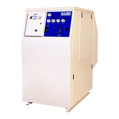
Bauer Compressors Mini Verticus ImVT 120 II Manual

Instruction Manual and Replacement Parts List
BAUER Compressors, Inc. Phone: (757) 855-6006
1328 Azalea Garden Road Fax: (757) 855-6224
Norfolk, Virginia 23502-1944 www.bauercomp.com
June 11, 2009 1st Edition, Rev. 0 Chg. 10 MNL-0408
© 2009 Bauer Compressors, Inc.
Mini Verticus
High Pressure Air Compressor Unit
ImVT 120 II (AP)

ImVT 120 II Mini Verticus
Page i 1st Edition, Rev. 0 Chg. 10
This information is believed to be accurate by Bauer Compressors, Inc., as of it’s date of publication,
but Bauer offers NO WARRANTY regarding the accuracy, or continuing accuracy, of the information
set forth herein. Bauer shall not be liable for inaccuracies in, or consequences resulting from, your use
of this information. All information supplied is in connection with sales of Bauer’s products, and is thus
subject to Bauer’s standard terms and conditions of sale. Bauer reserves the right to change this infor-
mation and has no obligation to update these materials. This information is © 2009 Bauer Compressors,
Inc., and Bauer reserves to itself all rights to this publication. Bauer’s customers have no right to repro-
duce, rewrite, modify, license or permit anyone else’s use of this information, without the express writ-
ten permission of Bauer Compressors, Inc.
EDITIONS, REVISIONS AND CHANGES
• An Edition is the original or a complete rewriting of the entire Manual.
• A Revision occurs whenever a complete Section or Appendix is rewritten or added.
• A Change occurs when individual pages, drawings or tables are changed.
^WARNING
This Instruction Manual and Replacement Parts List contains safety information and instructions for
the ImVT 120 II Mini Verticus High Pressure Air Compressor Unit.
You must read, understand and follow all safety precautions and instructions.
1st Edition January 25, 2006
Rev Chg Date Notes Auth
0 1 Feb. 16, 2006 Changed to PMV setting JD
0 2 Mar. 1, 2006 Changed Fig 8-3 item 5 P/N SWT-0257 to SWT-0256 JD
0 3 Mar. 16, 2006 Added Digital Pressure Switch to Chapter 8 JD
0 4 May 8, 2006 Changed Figure 1-2 to Digital pressure Switch JD
0 5 June 6, 2006 Replace Solenoid Valve N16382 with P/N N27009 & N27288 JD
0 6 Nov. 1, 2006 Changed DGM-2279 to DGM-2280 & P/N from N20320 to N02320 JD
07
Jan. 2, 2007 Changed 1st Stage Valve Head Assembly P/N to 080688
& Corrected 1st Stage Valve Head Illustrations JD
0 8 Mar. 22, 2007 Change to Separator P/N 079416 Life Span JD
0 9 May 21, 2007 Edited for Active Powers 460 V, 3 phase JD
0 10 June 11, 2009 Corrected 1st Stage Piston P/Ns SS

MNL-0408
June 11, 2009 Page ii
Table of Contents
CHAPTER 1:- - - - - - - - - - - - - - - - - - - - - INTRODUCTION
1.1 HOW TO USE THIS MANUAL.........................................................................................................................................1
1.1.1 Manual Safety Notices.......................................................................................................................................................1
1.2 HOW TO USE THE REPLACEMENT PARTS LIST....................................................................................................2
1.3 HOW TO USE THE APPENDIX.......................................................................................................................................3
1.4 COMPRESSOR UNIT DESIGN........................................................................................................................................4
1.4.1 Compressor Unit Major Assemblies..................................................................................................................................4
1.5 TECHNICAL SPECIFICATIONS.....................................................................................................................................6
1.5.1 Compressor Block..............................................................................................................................................................6
1.5.2 Compressor Drive Motor ...................................................................................................................................................6
1.5.3 Purification System Applicability......................................................................................................................................6
CHAPTER 2:- - - - - - - - PLC CONTROLLED UNIT OPERATIONS
2.1 PRE-START CHECKS.......................................................................................................................................................7
2.2 START-UP PROCEDURE .................................................................................................................................................7
2.3 POST START PROCEDURES ..........................................................................................................................................7
2.4 NORMAL OPERATIONS..................................................................................................................................................7
2.5 SHUTDOWN PROCEDURES ...........................................................................................................................................7
2.6 ELECTRIC PANEL COMPONENTS .............................................................................................................................8
2.6.1 Emergency Stop Switch.....................................................................................................................................................8
2.6.2 Starter Reset .......................................................................................................................................................................8
2.6.3 Compressor Control Switch...............................................................................................................................................9
2.6.3.1 2-Position (Standard)......................................................................................................................................................9
2.6.4 Indicator Lamps..................................................................................................................................................................9
2.6.4.1 PLC Warning and Alarm Lamps....................................................................................................................................9
2.6.4.1.1 Warning Lamp - Amber..................................................................................................................................................9
2.6.4.1.2 Alarm Lamp - Red..........................................................................................................................................................9
2.6.5 Hourmeter...........................................................................................................................................................................9
2.6.6 PLC Control .......................................................................................................................................................................9
2.7 WARNINGS ........................................................................................................................................................................9
2.7.1 One Flash - Final Separator Warning.................................................................................................................................9
2.7.2 Two Flashes - Securus Monitor (Optional)......................................................................................................................10
2.8 ALARMS............................................................................................................................................................................10
2.8.1 One Flash - Compressor High Temperature ....................................................................................................................10
2.8.2 Two Flashes - Compressor Low Oil Pressure..................................................................................................................10
2.8.3 Three Flashes - Compressor Overtime.............................................................................................................................10
2.8.4 Four Flashes - Securus Monitor.......................................................................................................................................10
2.8.5 Five Flashes - Carbon Monoxide Monitor (Optional) .....................................................................................................11
2.8.6 Six Flashes - Final Separator Shutdown ..........................................................................................................................11
2.8.7 Seven Flashes - Condensate Fault (OPT).........................................................................................................................11
2.8.8 On Steady - Motor Starter Overload Trip ........................................................................................................................11

ImVT 120 II Mini Verticus
Page iii 1st Edition, Rev. 0 Chg. 10
CHAPTER 3:- - - - - - - - - - - - - - MAINTENANCE AND PARTS
3.1 COMPRESSOR BLOCKS - IK120 II..............................................................................................................................12
3.1.1 Description .......................................................................................................................................................................12
3.1.2 Component Location........................................................................................................................................................12
3.1.3 Air Flow Diagram.............................................................................................................................................................13
3.1.4 Compressor Lubrication...................................................................................................................................................13
3.1.4.1 Description....................................................................................................................................................................13
3.1.4.2 Type of Oil....................................................................................................................................................................14
3.1.4.3 Oil Level Check............................................................................................................................................................15
3.1.4.4 Oil Change....................................................................................................................................................................16
3.1.5 Venting the Oil Pump.......................................................................................................................................................16
3.1.6 Intake Filter. .....................................................................................................................................................................17
3.1.6.1 Description....................................................................................................................................................................17
3.1.7 Intermediate Separator......................................................................................................................................................18
3.1.7.1 Maintenance..................................................................................................................................................................18
3.1.8 Cooling.............................................................................................................................................................................19
3.1.8.1 General..........................................................................................................................................................................19
3.1.9 Valves and Heads.............................................................................................................................................................19
3.1.9.1 Functional Description..................................................................................................................................................19
3.1.9.2 General Instructions for Changing the Valves..............................................................................................................20
3.1.9.3 Changing the IK120 II 1st Stage Valves ......................................................................................................................20
3.1.9.4 IK120 II 2nd Stage Valves............................................................................................................................................22
3.1.9.4.1 Removing the Valves of the 2nd Stage.........................................................................................................................22
3.1.9.4.2 Reassembling the Valves of the 2nd Stage...................................................................................................................23
3.1.9.5 IK120 II 3rd Stage Valves ............................................................................................................................................24
3.1.9.5.1 Removing the Valves of the 3rd Stage .........................................................................................................................24
3.1.9.5.2 Reassembling the Valves of the 3rd Stage....................................................................................................................25
3.1.10 Replacement Parts List.....................................................................................................................................................26
3.1.11 Troubleshooting................................................................................................................................................................44
3.1.11.1 Troubleshooting Table..................................................................................................................................................44
3.2 THREE STAGE AUTOMATIC CONDENSATE DRAIN SYSTEM...........................................................................45
3.2.1 Description .......................................................................................................................................................................45
3.2.1.1 Normal Operation .........................................................................................................................................................46
3.2.1.2 Condensate Drain..........................................................................................................................................................46
3.2.1.3 Start Unloading.............................................................................................................................................................46
3.2.1.4 Standstill Drainage........................................................................................................................................................47
3.2.2 ACD Maintenance............................................................................................................................................................47
3.2.3 ACD Replacement Parts List............................................................................................................................................48
3.3 CONDENSATE COLLECTOR .......................................................................................................................................52
3.3.1 Condensate Collector Replacement Parts List .................................................................................................................53
CHAPTER 4:- - - - - - - - - - IK120 II MAINTENANCE SCHEDULE
4.1 IK120 II MAINTENANCE INTERVALS.......................................................................................................................54
4.1.1 Maintenance Records .......................................................................................................................................................54
CHAPTER 5:- - - - - - - - - - - - - - - AIR PROCESSING SYSTEM
5.1 GENERAL..........................................................................................................................................................................55
5.1.1 General Purification System Procedures..........................................................................................................................55

MNL-0408
June 11, 2009 Page iv
5.1.2 Chamber Safety Bore.......................................................................................................................................................55
5.1.3 Manual Condensate Drainage ..........................................................................................................................................56
5.1.4 Model, Serial Number and Part Number Identification...................................................................................................56
5.1.4.1 Compressor Dataplate...................................................................................................................................................56
5.1.4.2 Purification System Dataplate ......................................................................................................................................56
5.1.4.3 Cartridge Installation Dataplate....................................................................................................................................56
5.1.4.4 Air Processing Cartridge Operating Hours Form.........................................................................................................57
5.2 P2S PURIFICATION SYSTEM MAJOR COMPONENTS .........................................................................................58
5.3 COMPONENT DESCRIPTION ......................................................................................................................................59
5.3.1 Oil and Water Separator ...............................................................................................................................................59
5.3.2 Chamber...........................................................................................................................................................................60
5.3.3 Cartridge...........................................................................................................................................................................60
5.3.3.1 Cartridge Construction..................................................................................................................................................60
5.3.3.2 Cartridge Handling .......................................................................................................................................................60
5.3.4 Condensate Drain Valve...................................................................................................................................................61
5.3.5 Check Valves....................................................................................................................................................................61
5.3.6 Bleed Valve......................................................................................................................................................................61
5.3.7 Pressure Maintaining Valve.............................................................................................................................................61
5.3.8 Safety Valve.....................................................................................................................................................................61
5.3.9 Securus®Electronic Moisture Monitor System................................................................................................................61
5.3.9.1 Securus®Cartridge........................................................................................................................................................61
5.3.9.2 Securus®Indicator ........................................................................................................................................................61
5.4 MAINTENANCE...............................................................................................................................................................62
5.4.1 Oil and Water Separator...................................................................................................................................................62
5.4.2 Cartridge Replacement.....................................................................................................................................................63
5.4.2.1 Leaking at the Safety Bore ...........................................................................................................................................64
5.5 REPLACEMENT PARTS LIST......................................................................................................................................65
CHAPTER 6:- - - - - - - - - - - - - - -COMPRESSOR UNIT DRIVE
6.1 VERTICAL SELF TENSIONING....................................................................................................................................70
6.2 MAINTENANCE OF THE V-BELT AND SHEAVES..................................................................................................70
6.2.1 Check the Flywheel and Sheave.......................................................................................................................................70
6.2.2 Check the V-belt...............................................................................................................................................................70
CHAPTER 7:- - - - - - - - - - - ELECTRICAL PANEL ASSEMBLY
7.1 OVERVIEW.......................................................................................................................................................................71
7.2 OPTIONS ...........................................................................................................................................................................72
7.3 AC POWER REQUIREMENTS......................................................................................................................................72
7.3.1 Transformer and Fuses.....................................................................................................................................................74
7.4 ELECTRIC PANEL COMPONENTS ...........................................................................................................................74
7.4.1 Motor Starter....................................................................................................................................................................74
7.4.2 Overload Relay.................................................................................................................................................................74
7.4.3 Emergency Stop Switch...................................................................................................................................................75
7.4.4 Starter Reset .....................................................................................................................................................................75
7.4.5 Compressor Control Switches..........................................................................................................................................76
7.4.5.1 2-Position (Standard)....................................................................................................................................................76
7.4.5.2 3-Position Compressor Control Switch (Factory Installed Option). ...........................................................................76
7.4.5.2.1 For Breathing Air Units................................................................................................................................................76

ImVT 120 II Mini Verticus
Page v 1st Edition, Rev. 0 Chg. 10
7.4.5.2.2 For Industrial Units.......................................................................................................................................................76
7.4.6 Indicator Lamps................................................................................................................................................................76
7.4.6.1 PLC Warning and Alarm Lamps..................................................................................................................................76
7.4.6.1.1 Warning Lamp - Amber................................................................................................................................................76
7.4.6.1.2 Alarm Lamp - Red........................................................................................................................................................76
7.4.7 Hour meter........................................................................................................................................................................76
7.4.8 PLC Control......................................................................................................................................................................76
7.4.8.1 PLC LED’s ...................................................................................................................................................................77
7.4.9 Compressor PLC Program Versions ................................................................................................................................78
7.4.10 PLC Inputs and Outputs ...................................................................................................................................................78
7.5 WARNINGS ......................................................................................................................................................................79
7.5.1 One Flash - Final Separator Warning...............................................................................................................................79
7.5.2 Two Flashes - Securus Monitor Warning.........................................................................................................................80
7.6 ALARMS ............................................................................................................................................................................80
7.6.1 One Flash - Compressor High Temperature.....................................................................................................................81
7.6.2 Two Flashes - Compressor Low Oil Pressure..................................................................................................................81
7.6.3 Three Flashes - Compressor Overrun Timer....................................................................................................................81
7.6.4 Four Flashes - Securus Monitor .......................................................................................................................................81
7.6.5 Five Flashes - Carbon Monoxide Monitor Alarm............................................................................................................82
7.6.6 Six Flashes - Final Separator Shutdown...........................................................................................................................82
7.6.7 Seven Flashes - Condensate Fault....................................................................................................................................83
7.6.8 On Steady - Motor Starter Overload Trip.........................................................................................................................84
7.7 INSTALLING A NEW PROGRAM................................................................................................................................84
7.7.1 Installing a new program using an EEPROM cartridge...................................................................................................85
7.8 OVERRUN TIMER...........................................................................................................................................................86
7.8.1 Adjusting the Overrun Timer ...........................................................................................................................................86
7.9 WIRE HARNESS CONNECTIONS ...............................................................................................................................87
7.10 REPLACEMENT PARTS LIST ......................................................................................................................................88
7.11 TROUBLE SHOOTING GUIDE......................................................................................................................................89
7.11.1 Compressor Will Not Start...............................................................................................................................................89
7.11.2 Compressor Is Shutdown, Alarm Code Flashing Sequence.............................................................................................89
7.11.2.1 One Flash - Compressor High Temperature.................................................................................................................89
7.11.2.2 Two Flashes - Compressor Low Oil Pressure ..............................................................................................................89
7.11.2.3 Three Flashes - Compressor Overtime .........................................................................................................................89
7.11.2.4 Four Flashes - Securus®Alarm.....................................................................................................................................90
7.11.2.5 Five Flashes - Carbon Monoxide Monitor Alarm ........................................................................................................90
7.11.2.6 Six Flashes - Final Separator Shutdown.......................................................................................................................90
7.11.2.7 Seven Flashes -Condensate Fault .................................................................................................................................90
7.11.2.8 On Steady - Motor Over load Trip................................................................................................................................91
7.11.2.9 Eight Flashes - High Inlet Pressure (Gas Compressors Only)......................................................................................91
7.11.2.10 Nine Flashes - Low Inlet Vacuum (Gas Compressors Only) .......................................................................................91
7.12 CHECK COMPRESSOR ROTATION DIRECTION...................................................................................................92
7.13 PLC INDUSTRIAL COMPRESSOR WIRING DIAGRAM .......................................................................................93
CHAPTER 8:- - - - - - - - PNEUMATIC VALVES AND CONTROLS
8.1 NONADJUSTABLE VALVES .........................................................................................................................................94
8.2 PRESSURE MAINTAINING VALVE.............................................................................................................................94
8.3 SAFETY VALVES.............................................................................................................................................................95

MNL-0408
June 11, 2009 Page vi
8.4 DIGITAL PRESSURE SWITCH.....................................................................................................................................96
8.5 PROGRAMMING THE PRESSURE SWITCH. ...........................................................................................................96
8.5.1 Selecting The Display Units.............................................................................................................................................97
8.5.2 Selecting The Unit Display..............................................................................................................................................97
8.5.3 Selecting The On Point For The Pressure Switch............................................................................................................97
8.5.4 Selecting The Off Point For The Pressure Switch. ..........................................................................................................98
8.5.5 locking And Unlocking The Switch.................................................................................................................................98
8.6 REPLACEMENT PARTS LIST......................................................................................................................................99
CHAPTER 9:- - - - - - - - - - - - - - - - - - - - - - - - APPENDIX
9.1 SAFETY............................................................................................................................................................................100
9.1.1 General Safety Precautions ............................................................................................................................................100
9.1.2 Safety Warning Labels...................................................................................................................................................102
9.2 UNPACKING, HANDLING AND INSTALLATION .................................................................................................103
9.2.1 Unpacking and Handling................................................................................................................................................103
9.2.2 Installation of the Compressor Unit...............................................................................................................................104
9.2.2.1 General........................................................................................................................................................................104
9.2.2.2 Ventilation ..................................................................................................................................................................104
9.2.2.2.1 Outdoor Installation....................................................................................................................................................104
9.2.2.2.2 Indoor Installation.......................................................................................................................................................105
9.2.2.2.3 Natural Ventilation .....................................................................................................................................................105
9.2.2.2.4 Forced Ventilation......................................................................................................................................................106
9.2.2.3 Electrical Installation..................................................................................................................................................106
9.2.2.3.1 Electric Drive..............................................................................................................................................................106
9.2.2.3.2 Electrical Supply.........................................................................................................................................................106
9.3 LONG TERM STORAGE...............................................................................................................................................109
9.3.1 General...........................................................................................................................................................................109
9.3.2 Preparations....................................................................................................................................................................109
9.3.2.1 Units Equipped with a Filter System..........................................................................................................................109
9.3.3 Preserving the Compressor.............................................................................................................................................109
9.3.4 Preventive Maintenance During Storage........................................................................................................................110
9.3.5 Lubrication Oils for Preservation...................................................................................................................................110
9.3.6 Reactivating the Compressor Unit .................................................................................................................................110
9.4 REPRODUCIBLE FORMS............................................................................................................................................111
9.4.1 Scheduled Maintenance Form........................................................................................................................................111
9.4.2 Record of Operating Hours............................................................................................................................................114
9.5 REFERENCE DATA.......................................................................................................................................................115
9.5.1 Tightening Torque Values..............................................................................................................................................115
9.5.2 Torque Sequence Diagrams ...........................................................................................................................................115
9.5.3 Conversion Formulas .....................................................................................................................................................115
9.5.4 Approved Lubricants Chart............................................................................................................................................116
9.5.5 Glossary of Abbreviations and Acronyms.....................................................................................................................116
9.6 ADDITIONAL DOCUMENTS ......................................................................................................................................117
9.6.1 Diagrams and Drawings.................................................................................................................................................117
9.6.2 Other Documents............................................................................................................................................................117

ImVT 120 II Mini Verticus
Page vii 1st Edition, Rev. 0 Chg. 10
List of Figures
CHAPTER 1:- - - - - - - - - - - - - - - - - - - - - INTRODUCTION
Figure 1-1 Compressor Identification Plate ..............................................................................................................................2
Figure 1-2 ImVT 120 II (AP) Front Panel.................................................................................................................................4
Figure 1-3 ImVT 120 II (AP) Rear View..................................................................................................................................5
CHAPTER 2:- - - - - - - - PLC CONTROLLED UNIT OPERATIONS
Figure 2-1 Electrical Panel Front ..............................................................................................................................................8
CHAPTER 3:- - - - - - - - - - - - - - MAINTENANCE AND PARTS
Figure 3-1 IK120 II Compressor Block...................................................................................................................................12
Figure 3-2 Air Flow Diagram..................................................................................................................................................13
Figure 3-3 Lubrication Oil Circuit ..........................................................................................................................................14
Figure 3-4 Oil Sight Glass.......................................................................................................................................................15
Figure 3-5 Oil Filler Cap.........................................................................................................................................................15
Figure 3-6 Removing the Oil Filter Cover ..............................................................................................................................15
Figure 3-7 Replacing the Oil Filter .........................................................................................................................................15
Figure 3-8 Intake Filter............................................................................................................................................................17
Figure 3-9 Intermediate Separator...........................................................................................................................................18
Figure 3-10 Valve Operation.....................................................................................................................................................19
Figure 3-11 IK120II Plate Valve...............................................................................................................................................19
Figure 3-12 IK120 II 1st Stage Valve .......................................................................................................................................21
Figure 3-13 IK120 II 2nd Stage Valves ....................................................................................................................................22
Figure 3-14 Using the Special Tool, P/N 082048 .....................................................................................................................23
Figure 3-15 Securing the Intake Valve......................................................................................................................................23
Figure 3-16 IK120 II 3rd Stage Valves.....................................................................................................................................24
Figure 3-17 Removing the 3rd Stage Pressure Valve ...............................................................................................................25
Figure 3-18 Crankcase Assembly..............................................................................................................................................26
Figure 3-19 Piston and Cylinder, 1st Stage, IK120 II...............................................................................................................28
Figure 3-20 Piston and Cylinder, 2nd Stage..............................................................................................................................29
Figure 3-21 Piston and Cylinder, 3rd Stage ..............................................................................................................................30
Figure 3-22 Piston and Sleeve, 3rd Stage..................................................................................................................................31
Figure 3-23 1st Stage Valve Head and Valve, IK120 II............................................................................................................32
Figure 3-24 2nd Stage Valves and Valve Head.........................................................................................................................34
Figure 3-25 3rd Stage Valves and Valve Head.........................................................................................................................36
Figure 3-26 Flywheel ................................................................................................................................................................37
Figure 3-27 Intermediate Separator...........................................................................................................................................38
Figure 3-28 Intake Filter............................................................................................................................................................39
Figure 3-29 IK120 II Cooling System.......................................................................................................................................40
Figure 3-30 Lubrication System Assembly...............................................................................................................................42
Figure 3-31 Automatic Condensate Drain.................................................................................................................................45
Figure 3-32 ACD Operation Diagrams .....................................................................................................................................46
Figure 3-33 ACD System..........................................................................................................................................................48

MNL-0408
June 11, 2009 Page viii
Figure 3-34 ACD Manifold Assembly......................................................................................................................................49
Figure 3-35 Condensate Drain Valve Assembly.......................................................................................................................50
Figure 3-36 Condensate Collector.............................................................................................................................................52
Figure 3-37 Condensate Collector.............................................................................................................................................53
CHAPTER 4:- - - - - - - - - -IK120 II MAINTENANCE SCHEDULE
There are no Figures in this Chapter
CHAPTER 5:- - - - - - - - - - - - - - - AIR PROCESSING SYSTEM
Figure 5-1 Cartridge Safety Venting.......................................................................................................................................55
Figure 5-2 Purification System Dataplates (typical)...............................................................................................................56
Figure 5-3 P2S Purification System........................................................................................................................................58
Figure 5-4 Oil and Water Separator........................................................................................................................................59
Figure 5-6 Cartridge................................................................................................................................................................60
Figure 5-5 Oil and Water Separator Labels ............................................................................................................................60
Figure 5-7 Oil and Water Separator........................................................................................................................................63
Figure 5-8 Sintered Metal Filter Assembly.............................................................................................................................63
Figure 5-9 Cartridge Replacement..........................................................................................................................................63
Figure 5-10 P2S Purification System........................................................................................................................................65
Figure 5-11 Oil and Water Separator........................................................................................................................................66
Figure 5-12 Securus®Electronic Moisture Monitor System.....................................................................................................68
CHAPTER 6:- - - - - - - - - - - - - - -COMPRESSOR UNIT DRIVE
Figure 6-1 Vertical Motor Mount (typical).............................................................................................................................70
CHAPTER 7:- - - - - - - - - - - ELECTRICAL PANEL ASSEMBLY
Figure 7-1 Electrical Panel Assembly.....................................................................................................................................71
Figure 7-2 Electrical Panel Label............................................................................................................................................73
Figure 7-3 Transformer and Fuses ..........................................................................................................................................73
Figure 7-4 Motor Starter and Overload Relay ........................................................................................................................74
Figure 7-5 Electrical Panel Assembly.....................................................................................................................................75
Figure 7-6 PLC CNT-0052 .....................................................................................................................................................77
Figure 7-7 Status Lights..........................................................................................................................................................77
Figure 7-8 Securus®System....................................................................................................................................................80
Figure 7-9 High Temperature Switch......................................................................................................................................81
Figure 7-10 Low Oil Pressure Switch.......................................................................................................................................81
Figure 7-11 CO Monitor ...........................................................................................................................................................82
Figure 7-12 Condensate Level Float Switch.............................................................................................................................83
Figure 7-13 PLC Programming Port.........................................................................................................................................84
Figure 7-14 PLC EEPROM.......................................................................................................................................................85
Figure 7-15 Overrun Timer Adjustment ...................................................................................................................................86
Figure 7-16 Electrical Panel......................................................................................................................................................88
Figure 7-17 Checking Compressor Rotation Direction.............................................................................................................92

ImVT 120 II Mini Verticus
Page ix 1st Edition, Rev. 0 Chg. 10
CHAPTER 8:- - - - - - - - PNEUMATIC VALVES AND CONTROLS
Figure 8-1 Pressure Maintaining Valve...................................................................................................................................94
Figure 8-2 Safety Valve...........................................................................................................................................................95
Figure 8-3 Digital Pressure Switch..........................................................................................................................................96
Figure 8-4 Switches and Valves..............................................................................................................................................99
CHAPTER 9:- - - - - - - - - - - - - - - - - - - - - - - - -APPENDIX
Figure 9-1 Lifting Devices ....................................................................................................................................................103
Figure 9-2 Incoming Power Wiring Label ............................................................................................................................107
Figure 9-3 6 Bolt and 4 Bolt Torque Sequence.....................................................................................................................115

MNL-0408
June 11, 2009 Page 1
CHAPTER 1: INTRODUCTION
1.1 How To Use This Manual
This manual contains the operating and maintenance instructions for the Bauer Compressors, Inc. prod-
ucts listed on the front cover.
All instructions in this manual should be observed and carried out as written to prevent damage or prema-
ture wear to the product or the equipment served by it.
If your unit is equipped with nonstandard accessories and or options, supplemental information is nor-
mally included in other documentation; i.e. OEM Manuals or additional Bauer Manuals.
While every effort is made to ensure the accuracy of the information contained in this manual, Bauer
Compressors, Inc. will not, under any circumstances be held accountable for any inaccuracies or the con-
sequences thereof.
1.1.1 Manual Safety Notices
Important instructions concerning the endangerment of personnel, technical safety or operator safety will
be specially emphasized in this manual by placing the information in the following types of safety
notices.
^DANGER
DANGER indicates an imminently hazardous situation which, if not avoided, will result in death or seri-
ous injury. This is limited to the most extreme situations.
^WARNING
WARNING indicates a potentially hazardous situation which, if not avoided, could result in death or
injury.
^CAUTION
CAUTION indicates a potentially hazardous situation which, if not avoided, may result in minor or mod-
erate injury. It may also be used to alert against unsafe practices.
NOTICE
NOTE advise of technical requirements that require particular attention by the operator or the mainte-
nance technician for proper maintenance and utilization of the equipment.

ImVT 120 II Mini Verticus
Page 2 1st Edition, Rev. 0 Chg. 10
1.2 How to Use the Replacement Parts List
• A lozenge ♦in the Item Number column indicates the part number for a complete assembly.
• a dagger (†) in the Qty column with or without an ellipse (…) in the Part Number column means the
part is illustrated for assembly purposes only and is not available for sale as an individual component.
This part can be obtained by ordering the complete assembly.
• AR in the Qty column means that the item is cut or manufactured to the size which the customer spec-
ifies.
• A dash (—) in the Item Number column indicates that there is more than one part number applicable
to the preceding Item Number.
• The letters in the columns labeled Kit indicate the number of operating hours when the part is to be
replaced; a = replaced every 1,000 hours, b = replaced every 2,000 hours and c= replaced every 4,000
hours.
• NS in the Item Number column indicates the part is not illustrated but is available.
When placing an order for spare parts, please provide the following information to ensure delivery of the
correct parts. The model number, date of manufacture and serial number can be found of the compressor
unit identification plate on the compressor unit frame.
Information Example
Model Number TCom-25
Serial Number 32165
Date of Manufacture 02/2005
Quantity required 2
Part Number N04860
Part Description Valve
Figure 1-1 Compressor Identification Plate
BAUER
COMPRESSORS
BAUER COMPRESSORS, INC.
NORFOLK, VIRGINIA U.S.A
LBL-004
MODEL NO.
BLOCK NO.
CAPACITY
CFM
CHG. RATE
CFM
MOTOR HP
SPEED
RPM
SERIAL NO.
PRESSURE
PSIG
VOLTS
PH
HZ AMPS
DATE OF MANUFACTUREDATE OF MANUFACTURE

MNL-0408
June 11, 2009 Page 3
1.3 How to Use the Appendix
Information contained in the Appendix to this manual includes the following.
• The safety instructions applicable to this product. They must be read, understood and complied with
prior to operating the product.
• The instructions for installing this product. They must be read, understood and complied with prior to
operating the product.
• The instructions for long term storage (over 90 days) of this product.
• Reproducible Forms
• Reference Data
• Torque Values
• Torque Sequence
• Conversion Formulas
• Approved Lubricants
• Glossary of Abbreviations & Acronyms
• Additional Documents
^WARNING
The use of repair parts other than those included in the Bauer Replacement Parts Lists may create unsafe
conditions over which Bauer has no control. Such unsafe conditions can lead to accidents that may be
life-threatening, cause substantial bodily injury, and/or result in damage to the equipment. Therefore,
Bauer Compressors, Inc. can bear no responsibility for equipment in which unapproved repair parts are
installed.

ImVT 120 II Mini Verticus
Page 4 1st Edition, Rev. 0 Chg. 10
1.4 Compressor Unit Design
The ImVT 120 II Mini Verticus high pressure compressor unit is used for applications in the high
pressure range, up to 5000 psig (350 bar). The compressor units of this series are manufactured with a
standard type frame with enclosure panels. Standard equipment includes an automatic condensate drain
system, instrument panel with oil pressure and interstage pressure, hourmeter, and a P2 purification sys-
tem with Securus®moisture monitoring system. The approximate weight of the ImVT 120 II Mini Ver-
ticus compressors is 700 to 750 lbs.
1.4.1 Compressor Unit Major Assemblies
The compressor unit is comprised of the following major assemblies.
Compressor Block Drive Motor Base and Frame Assembly
Automatic Condensate Drain System Electric Control System Enclosure Panels
Figure 1-2 ImVT 120 II (AP) Front Panel
1. Compressor Control Switch
2. Warning Lamp
3. Alarm Lamp
4. Hourmeter
5. Motor Reset Button
6. Emergency Stop Switch
7. Compressor Oil Pressure Gauge
8. Interstage Air Pressure Gauges
1
2
3
4
5
6
7
8

MNL-0408
June 11, 2009 Page 5
Figure 1-3 ImVT 120 II (AP) Rear View
1. Securus®Monitor
2. Securus®Chamber
3. Final Pressure Switch
4. Pressure Maintaining Valve
5. Air Outlet
6. Check Valves
7. Purification Chamber Vent Valve
8. Final Pressure Gauge
9. Securus®Chamber Wrench Holder
1
2
3
4
5
6
9
6
7
8

ImVT 120 II Mini Verticus
Page 6 1st Edition, Rev. 0 Chg. 10
1.5 Technical Specifications
All technical data is subject to change without prior notice.
Medium Air
Free Air Delivery 7.0 scfm ((198 l/min)1
Inlet pressure atmospheric
Operating pressure, max. 5,000 psig (350 bar)
Ambient temperature range 41 to 113 °F (5 to 45 °C)
1.5.1 Compressor Block
IK120 II Mod. 7
No. of stages 3
No. of cylinders 3
Cylinder bore, 1st stage 3.46 in. (88 mm)
Cylinder bore, 2nd stage 1.42 in. (36 mm)
Cylinder bore, 3rd stage 0.55 in. (14 mm)
Piston Stroke 1.57 in.(40 mm)
Intermediate pressure, 1st stage 87 - 102 psig (6 - 7 bar)
Safety valve setting, 1st stage 131 psig (9 bar)
Intermediate pressure, 2nd stage 464 -711 psig (40 - 49 bar)
Safety valve setting, 2nd stage 870 psig (60 bar)
Direction of rotation when facing flywheel CCW
Compressor speed 1,385 RPM
Oil capacity 2.96 qts.(2.8 liters)
Oil Pressure 58 - 87 psig (4 - 6 bar)
Recommended oil BAUER OIL-0024
Maximum Inclination 10° in all directions
1.5.2 Compressor Drive Motor
1.5.3 Purification System Applicability
The purification system supplied with this order is the P2 system with the Securus®Moisture Monitor-
ing System.
1. Referenced to standard inlet conditions of 68°F and 60% humidity at sea level.
Model Voltage, Phase, Frequency Power RPM Type Part No.
-E3 208-460 VAC, 3Φ, 60 Ηz 7.5 Hp 3,600 ODP MTR-0033

MNL-0408
June 11, 2009 Page 7
CHAPTER 2: PLC CONTROLLED UNIT OPERATIONS
2.1 Pre-start Checks
1. Ensure that all scheduled maintenance is completed.
2. Check compressor oil level. Refer to Chapter 3.
3. Check Emergency Stop Switch is pulled out.
2.2 Start-up Procedure
(See Figure 2-1)
1. Verify that all connections downstream of the compressor are secure.
2. Apply electric power to the unit.
3. Pull out Emergency Shop Switch.
4. Turn the Compressor Control Switch to the ON position.
2.3 Post Start Procedures
1. Allow the compressor to build up pressure. Monitor the pressure gauge.
2. Listen to the unit as it operates. If excessive knocking or vibrations are observed shut down the unit.
3. Allow the compressor to reach full pressure.
2.4 Normal Operations
The compressor will operate automatically as needed while the Control Switch is in the ON position,
The Emergency Stop Switch is pulled out, power is applied to the control circuit and there are no fault
conditions.
2.5 Shutdown Procedures
1. Verify all bottle valves and fill valves are closed.
2. Turn the Compressor Control Switch to the OFF position.
3. Leave Emergency Stop Switch pulled out for at least 8 hours every 30 days to maintain the charge
on the internal PLC battery and preserve the PLC operating memory.
4. If the compressor is to remain idle for six months or longer, refer to the Appendix titled, Long Term
Storage for preservation instructions.

ImVT 120 II Mini Verticus
Page 8 1st Edition, Rev. 0 Chg. 10
2.6 Electric Panel Components
See Figure 2-1
2.6.1 Emergency Stop Switch.
The Emergency Stop Switch is a switch with a large, red mushroom head. The button must be pulled
out for the unit to operate. In an emergency, depress the push button, which will shutdown the electric
motor and all other periphery devices. Do not use the Emergency Stop Switch for securing the equip-
ment under normal operation, use the Compressor Control Switch. The PLC operating memory is main-
tained by a internal battery in the PLC. Removing all power from the compressor will allow the battery
to discharge over a 30 day period. To recharge the PLC battery apply power to the unit, put the Control
Switch in the OFF position, pull out the Emergency Stop Switch, and allow the battery to charge for at
least 8 hours every 30 days.
2.6.2 Starter Reset
The Starter Reset is a blue push button with the letter “R” at its center. Pushing this button will reset the
thermal overload relay on the motor starter. Should the electric motor have overloaded and tripped out
Figure 2-1 Electrical Panel Front
1. Compressor Control Switch
2. Warning Light
3. Alarm Light
4. Hourmeter
5. Starter Reset
6. Emergency Stop Switch
1
2
3
4
5
6

MNL-0408
June 11, 2009 Page 9
during normal operation, then depressing this button after giving the motor starter some time to cool,
will reset the overload relay portion of the motor starter. An Overload Fault is indicated by the red
Alarm Light on steady (not flashing).
2.6.3 Compressor Control Switch
2.6.3.1 2-Position (Standard)
OFF Position - The Compressor Control Switch switch must be in the OFF position when securing the
compressor system.
ON Position - The Compressor Control Switch switch must be in the ON position to operate the com-
pressor system. When positioning the switch to the ON position, it will illuminate Green. The compres-
sor will start and stop automatically based on the status of the pressure switch.
2.6.4 Indicator Lamps
2.6.4.1 PLC Warning and Alarm Lamps
2.6.4.1.1 Warning Lamp - Amber
The Warning Lamp is a LED lamp for long trouble free life. This lamp will flash a code IAW the logic
of the PLC. See Paragraph 2.7.
2.6.4.1.2 Alarm Lamp - Red
The Alarm Lamp is a LED lamp for long trouble free life. This lamp will flash a code IAW the logic of
the PLC. See Paragraph 2.8.
2.6.5 Hourmeter
The panel is supplied with an hourmeter. The hourmeter is not resettable and used to monitor the run
hours of the compressor. It is powered with a 120 VAC signal supplied from the auxiliary contact on
the motor starter.
2.6.6 PLC Control
This panel will be controlled with a Telemecanique 16 I/O Twido Programmable Logic Controller. This
unit will provide logical operations to the overall system that includes the high pressure compressor,
purification systems, and other accessories.
2.7 Warnings
The amber Warning Lamp located on the control panel flashes warning codes with a 0.5 second on, 0.5
second off sequence with a distinct pause between sequences. In addition the light will illuminate on
initial start up for a period of 5 seconds, to serve as a lamp test function. The lamp is a LED lamp for
long trouble free life.
2.7.1 One Flash - Final Separator Warning
The compressor unit is equipped with a final separator. To prevent fatigue failure of this pressure ves-
sel, the PLC program monitors the pressurization, de-pressurization cycles of the separator and will
first issue a Warning, and then an Alarm. The program is set up to provide the warning at 90% of the
maximum recommended number of cycles. The program is configured to reflect these values when it is
built. When the warning is illuminated, the unit will still continue to function properly, but will prompt
the operator to contact Bauer Compressors for making arrangements to replace the Final Separator.
When the Alarm level has been achieved, the compressor will no longer function, and will require the
replacement of the Final Separator. Once the Final Separator is replaced, the unit can be re-activated by
making adjustments to the PLC. Please contact Bauer Product Support for detailed instructions on this
procedure.

ImVT 120 II Mini Verticus
Page 10 1st Edition, Rev. 0 Chg. 10
2.7.2 Two Flashes - Securus Monitor (Optional)
The compressor purification system may be equipped with an optional Securus®Electronic Moisture
Monitor. This consists of a control module and cable connected to the purification chamber. It functions
as a capacitive sensor, sensing the moisture in the purified air. When the chemicals in the purification
cartridges have reached the point where they retain a set level of moisture, the Securus®monitor will
issue a warning via the amber Warning Light. On a Securus®Warning condition, the compressor will
run normally, the PLC I7 lamp will illuminate, and the warning code will flash. This warning is meant
to prompt the operator to schedule replacement of the purification cartridge.
2.8 Alarms
The red Warning Light located on the control panel flashes warning codes with a 0.5 second on, 0.5
second off sequence with a distinct pause between sequences.In addition the light will illuminate on ini-
tial start up for a period of 5 seconds, to serve as a lamp test function. The lamp is a LED lamp for long
trouble free life.
2.8.1 One Flash - Compressor High Temperature
The compressor high temperature switch is located on the compressor block, third, fourth or fifth stage
head, depending on model. Under normal operating conditions, the switch is closed and the I1 lamp on
the PLC is illuminated. On a high temperature condition, the compressor will shutdown, the I1 lamp
will extinguish, and the alarm code will flash.
2.8.2 Two Flashes - Compressor Low Oil Pressure
The compressor oil pressure switch is located on the back of the compressor block, mounted with the
oil pressure gauge. The switch is N.O., Normally Open, and is connected to the PLC on terminal I2.
During startup of the compressor, the oil pressure switch is bypassed for a period of 45 seconds to allow
the oil pressure to stabilize, then the switch will close. Then should the compressor lose oil pressure, the
compressor will shutdown, the I2 lamp will extinguish, and the alarm code will flash.
2.8.3 Three Flashes - Compressor Overtime
The compressor has an overtime function, where if the compressor runs continuously for 5 hours, then
the compressor will shutdown, and the alarm code will flash. This is done to secure the equipment if it
were to be started and left unattended.
2.8.4 Four Flashes - Securus Monitor
The compressor purification system is equipped with a Securus®Electronic Moisture Monitor. This
consists of a control module and cable connected to the purification chamber. It functions as a capaci-
tive sensor, sensing the moisture in the purified air. When the chemicals in the purification cartridge has
reached the point where it retains a set level of moisture, the Securus®monitor will issue an alarm via
the red Alarm Light. On a Securus®ALARM condition, the compressor will shutdown, the PLC I5
lamp will be illuminated, and the alarm code will flash.
^WARNING
Do not attempt to override the Separator Shutdown Warning.
This feature is provided to protect personnel from injury or death.
Table of contents
Other Bauer Compressors Air Compressor manuals
Popular Air Compressor manuals by other brands

Tecumseh
Tecumseh AG installation instructions

Armour & Danforth
Armour & Danforth SYSTEM SILENT-ONE SY092 manual

Blitz
Blitz VARIS operating instructions

ABAC
ABAC Pro A29B/50 CM3 manual

Bostitch
Bostitch BTFP02040 Operation and maintenance manual

Campbell Hausfeld
Campbell Hausfeld VT6333 operating instructions