Bauer Compressors MAXI VERTICUS Manual
BAUER
BAUER
COMPRESSORS
Instruction Manual and Replacement Parts List
BAUER Compressors, Inc. Phone: (757) 855-6006
1328 Azalea Garden Road Fax: (757) 855-6224
Norfolk, Virginia 23502-1944 www.bauercomp.com
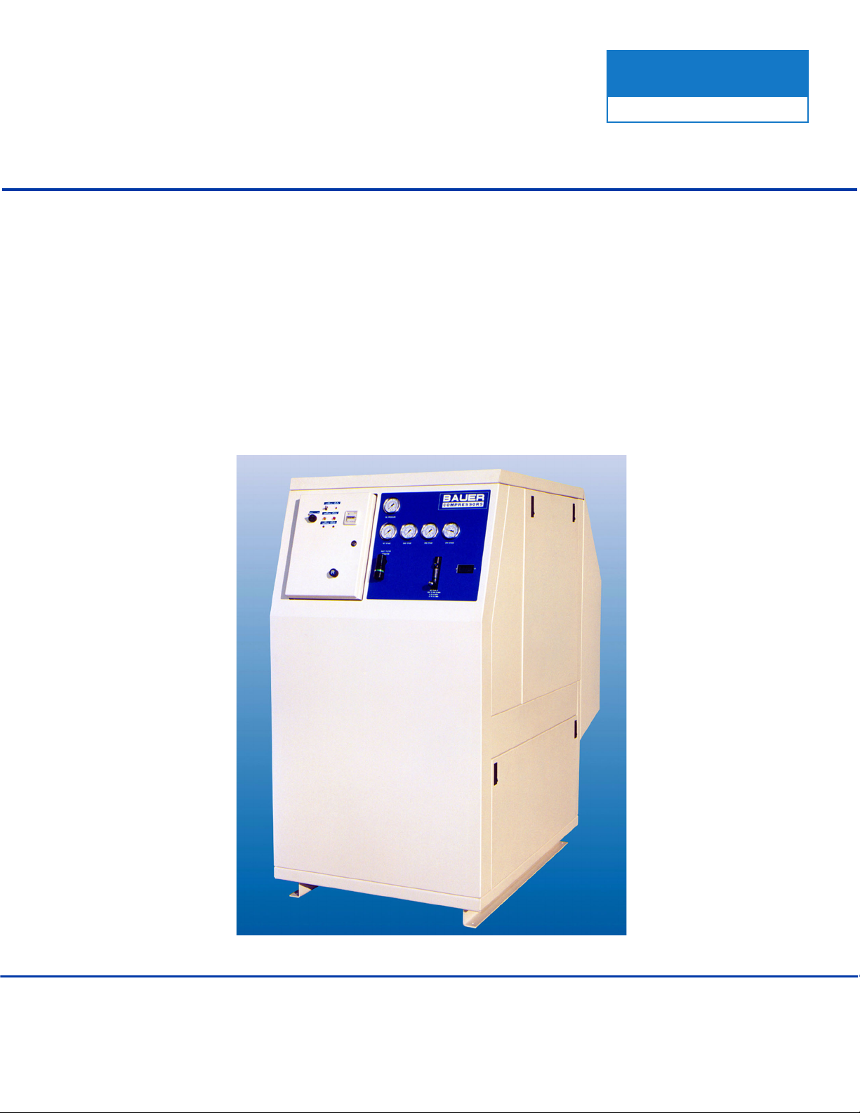
MAXI VERTICUS
High Pressure Breathing Air Compressor
MVT26
October 2003 MNL- 0345

MVT26
October 2003 Section 1 Page 1
SECTION 1: INTRODUCTION
1.1 General
1.1.1 How To Use This Manual
This manual contains the operating and maintenance instructions for the Bauer Compressors, Inc. product
listed on the front cover.
All instructions in this manual should be observed and carried out as written to prevent damage or prema-
ture wear to the product or the equipment served by it.
If these operating instruction are not followed or changes are made to the product without prior written
authorization, including the use of parts not supplied by Bauer Compressors, Inc., any claims under war-
ranty shall be void. Please contact our customer service department at the number listed on the front of
this manual for assistance.
The instructions for installing this product are contained in Section A.4 of this manual. They must be
read, understood and complied with prior to operating the product.
The safety instructions applicable to this product are contained in Section A.2. They must be read, under-
stood and complied with prior to operating the product.
The instructions for long term storage (over 90 days) of this product are contained in Section A.3
Section A.5 is a set of forms which may be reproduced as needed to record operating hours, purification
cartridge adjusted operating hours, scheduled maintenance actions or suggested corrections to this man-
ual.
If your unit is equipped with nonstandard accessories and/or options, supplemental information is nor-
mally included in other documentation; i.e. OEM Manuals or additional Bauer Manuals.
Important instructions concerning the endangerment of personnel, technical safety or operator safety will
be specially emphasized in this manual by placing the information in the following types of safety notices
WARNING
Data contained in this notice must be adhered to exactly in order to avoid endangering personnel
CAUTION
Data contained in this notice must be complied with in order to avoid damage to or destruction of
the machine or its associated equipment.
NOTE
Data contained in this notice advises of technical requirements that require particular attention by
the operator or the maintenance technician

MNL- 0345
Page 2 Section 1 Base Edition
While every effort is made to ensure the accuracy of the information contained in this manual, Bauer
Compressors, Inc. will not, under any circumstances be held accountable for any inaccuracies or the con-
sequences thereof.
1.1.2 How to Use the Replacement Parts List
• The use of repair parts other than those included in the Bauer Replacement Parts Lists may create
unsafe conditions over which Bauer has no control. Such unsafe conditions can lead to accidents
that may be life-threatening, cause substantial bodily injury, and/or result in damage to the equip-
ment. Therefore, BAUER Compressors, Inc. can bear no responsibility for equipment in which
non-approved repair parts are installed.
• A lozenge ◊in the Item Number column indicates the part number for a complete assembly.
• a dagger (†) in the Qty column with or without an ellipis (…) in the Part Number column means
the part is illustrated for assembly purposes only and is not available for sale as an individual
component. This part can be obtained by ordering the complete assembly.
• AR in the Qty column means that the item is cut or manufactured to the size which the customer
specifies.
• A dash (—) in the Item Number column indicates that there is more than one part number appli-
cable to the preceding Item Number.
When placing an order for spare parts, please provide the following information to ensure delivery of the
correct parts.
Model Number Date of Manufacture
Serial Number Quantity required
Part Number Part Description
Example: Junior-E3; manufactured 1998; Serial number 32165; requiring 2 reed valves, p/n N04860.
The model number, date of manufacture and serial number can be found of the compressor unit identifi-
cation plate on the compressor unit’s frame.
Figure 1-1 Compressor Unit Identification Plate
BAUER
COMPRESSORS
BAUER COMPRESSORS, INC.
NORFOLK, VIRGINIA U.S.A
LBL-004
MODEL NO.
BLOCK NO.
CAPACITY
CFM
CHG. RATE
CFM
MOTOR HP
SPEED
RPM
SERIAL NO.
PRESSURE
PSIG
VOLTS
PH
HZ AMPS
DATE OF MANUFACTURE
DATE OF MANUFACTURE

MVT26
October 2003 Section 1 Page 3
1.1.3 Revisions and Changes
Ed.\Rev.\Change Date Notes Approval
1st Edition October 2003 JD
Ed\Rev\Change Effected Pages Ed\Rev\Change Effected Pages

MNL- 0345
Page 4 Section 1 Base Edition
1.2 Table of Contents
No. Title Page
SECTION 1: INTRODUCTION
1.1 General .......................................................................................................................................................................................1
1.1.1 How To Use This Manual......................................................................................................................................................1
1.1.2 How to Use the Replacement Parts List.................................................................................................................................2
1.1.3 Revisions and Changes ..........................................................................................................................................................3
1.2 Table of Contents .......................................................................................................................................................................4
1.3 List of Figures ............................................................................................................................................................................8
1.4 Description and Specifications.................................................................................................................................................12
1.4.1 Unit Description...................................................................................................................................................................12
1.4.2 Unit Specifications...............................................................................................................................................................13
1.4.2.1 MVT26-E3 .......................................................................................................................................................................13
1.4.2.1.1 Compressor Block, IK180II ..............................................................................................................................................13
1.4.2.1.2 Compressor Drive .............................................................................................................................................................13
1.4.2.1.3 Purification System Applicability .....................................................................................................................................13
No. Title Page
SECTION 2: OPERATIONS
2.5 Electric Motor Driven Units ....................................................................................................................................................14
2.5.1 Pre-start Checks ...................................................................................................................................................................14
2.5.2 Start-up Procedure................................................................................................................................................................14
2.5.3 Post Start Procedures ...........................................................................................................................................................14
2.5.4 Shutdown Procedures...........................................................................................................................................................14
No. Title Page
SECTION 3: MAINTENANCE AND PARTS
3.1 IK150 II and IK180 II Compressor Blocks..............................................................................................................................15
3.1.1 Description ...........................................................................................................................................................................15
3.1.1.1 Air Flow Diagram .............................................................................................................................................................15
3.1.1.2 Component Location.........................................................................................................................................................16
3.1.2 Lubrication System ..............................................................................................................................................................17
3.1.2.1 Description. .......................................................................................................................................................................17
3.1.2.2 Oil Level Check ................................................................................................................................................................18
3.1.2.3 Oil Change Interval ...........................................................................................................................................................18
3.1.2.4 Oil Capacity ......................................................................................................................................................................18
3.1.2.5 Oil Change ........................................................................................................................................................................18
3.1.2.6 Venting the Oil Pump........................................................................................................................................................19
3.1.3 Intake Filter ..........................................................................................................................................................................20
3.1.3.1 Description ........................................................................................................................................................................20
3.1.3.2 Maintenance ......................................................................................................................................................................20
3.1.4 Intermediate Separators........................................................................................................................................................22
3.1.4.1 Description ........................................................................................................................................................................22
3.1.4.2 Maintenance ......................................................................................................................................................................22

MVT26
October 2003 Section 1 Page 5
3.1.4.2.1 2nd Stage Intermediate Separator .................................................................................................................................... 22
3.1.4.2.2 3rd Stage Intermediate Separator..................................................................................................................................... 22
3.1.5 Compressor Valves and Valve Heads.................................................................................................................................. 23
3.1.5.1 Functional Description...................................................................................................................................................... 23
3.1.5.2 Initial Operational Check of the Valves............................................................................................................................ 23
3.1.5.3 General Instructions for Changing the Valves.................................................................................................................. 23
3.1.5.4 Changing the 1st Stage Valves. ........................................................................................................................................ 24
3.1.5.4.1 Removal Procedure........................................................................................................................................................... 24
3.1.5.4.2 Installation Procedure ....................................................................................................................................................... 24
3.1.5.5 Changing the 2nd and 3rd Stage Valves ........................................................................................................................... 25
3.1.5.5.1 Removal Procedure ........................................................................................................................................................... 25
3.1.5.5.2 Installation Procedure ....................................................................................................................................................... 25
3.1.5.6 Changing the 4th Stage Valves ......................................................................................................................................... 26
3.1.5.6.1 Discharge Valve Removal Procedure .............................................................................................................................. 26
3.1.5.6.2 Discharge Valve Installation Procedure........................................................................................................................... 26
3.1.5.6.3 Inlet Valve Removal and Installation .............................................................................................................................. 27
3.1.6 Repair and Troubleshooting................................................................................................................................................. 27
3.1.6.1 Repair ................................................................................................................................................................................ 27
3.1.6.2 Troubleshooting ................................................................................................................................................................ 28
3.1.7 Replacement Parts List ........................................................................................................................................................ 30
3.2 4 Stage Automatic Condensate Drain System ......................................................................................................................... 58
3.2.1 Description........................................................................................................................................................................... 58
3.2.1.1 Compressor Operating ...................................................................................................................................................... 59
3.2.1.2 Condensate Draining......................................................................................................................................................... 59
3.2.1.3 Start Unloading ................................................................................................................................................................. 60
3.2.1.4 Standstill Drainage............................................................................................................................................................ 60
3.2.1.5 Condensate Drain Piping .................................................................................................................................................. 60
3.2.1.6 Electrical Connections ...................................................................................................................................................... 60
3.2.1.7 ACD Timer ...................................................................................................................................................................... 60
3.2.1.8 Condensate Drain Separator ............................................................................................................................................. 61
3.2.1.9 ACD Maintenance ............................................................................................................................................................ 61
3.2.2 Replacement Parts List ........................................................................................................................................................ 62
3.2.3 Trouble shooting .................................................................................................................................................................. 68
No. Title Page
SECTION 4: SCHEDULING MAINTENANCE
4.1 Maintenance Schedules............................................................................................................................................................ 69
4.1.1 Initial start-up or after maintenance..................................................................................................................................... 69
4.1.2 Calendar intervals ................................................................................................................................................................ 69
4.1.3 Operating hours.................................................................................................................................................................... 70
4.1.4 Maintenance Records........................................................................................................................................................... 71
No. Title Page
SECTION 4: PURIFICATION SYSTEMS
4.1 General..................................................................................................................................................................................... 72
4.1.1 System Configurations......................................................................................................................................................... 72
4.1.2 General Purification System Procedures ............................................................................................................................. 72
4.1.3 Chamber Safety Bore........................................................................................................................................................... 73

MNL- 0345
Page 6 Section 1 Base Edition
4.1.4 Manual Condensate Drainage ..............................................................................................................................................73
4.1.5 Model, Serial Number and Part Number Identification.......................................................................................................73
4.1.5.1 Compressor Dataplate .......................................................................................................................................................73
4.1.5.2 Purification System Dataplate...........................................................................................................................................73
4.1.5.3 Cartridge Installation Dataplate ........................................................................................................................................74
4.1.6 Cartridge Operating Life......................................................................................................................................................74
4.1.6.1 Calculating the Maximum Cartridge Operating Hours.....................................................................................................75
4.1.6.2 Calculating the Adjusted Cartridge Operating Hours .......................................................................................................75
4.1.7 Air Purification Cartridge Operating Hours.........................................................................................................................77
4.2 P5 Purification System............................................................................................................................................................78
4.2.1 Component Description .......................................................................................................................................................78
4.2.1.1 Chamber ............................................................................................................................................................................78
4.2.1.2 Cartridge............................................................................................................................................................................79
4.2.1.2.1 Cartridge Construction .....................................................................................................................................................79
4.2.1.2.2 Cartridge Handling............................................................................................................................................................79
4.2.1.3 Coalescing Oil/Water Separator........................................................................................................................................79
4.2.1.4 Condensate Drain Valve ...................................................................................................................................................79
4.2.1.5 Check Valves ....................................................................................................................................................................79
4.2.1.6 Bleed Valve.......................................................................................................................................................................79
4.2.1.7 Pressure Maintaining Valve ..............................................................................................................................................79
4.2.1.8 Safety Valve ......................................................................................................................................................................80
4.2.1.9 Securus®Electronic Air Purification Monitoring System................................................................................................80
4.2.1.9.1 Securus®Cartridge ............................................................................................................................................................80
4.2.1.9.2 Securus®Indicator ............................................................................................................................................................80
4.2.2 Maintenance .........................................................................................................................................................................80
4.2.2.1 Coalescing Oil/Water Separator........................................................................................................................................80
4.2.2.2 Cartridge Replacement......................................................................................................................................................82
4.2.2.3 Leaking at the Safety Bore................................................................................................................................................82
No. Title Page
SECTION 5: COMPRESSOR UNIT DRIVE
5.1 Vertical Compressor Drive ......................................................................................................................................................88
5.1.1 Maintenance of the V-belt and Sheaves...............................................................................................................................89
5.1.1.1 Check The Sheaves. ..........................................................................................................................................................89
5.1.1.2 Check the V-belt ...............................................................................................................................................................89
No. Title Page
SECTION 6: MISCELLANEOUS
6.1 Pneumatic Valves and Controls ...............................................................................................................................................90
6.1.1 Nonadjustable Valves ..........................................................................................................................................................90
6.1.2 Pressure Maintaining Valve .................................................................................................................................................90
6.1.3 Safety Valves .......................................................................................................................................................................91
6.2 Electrical Controls and Indicators............................................................................................................................................92
6.2.1 Pressure Switch ....................................................................................................................................................................92
6.2.1.1 Operating Set Point Adjustment........................................................................................................................................92
6.2.1.1.1 Switch characteristics........................................................................................................................................................92
6.2.1.2 Indicators...........................................................................................................................................................................93
6.2.1.3 Replacement Parts List......................................................................................................................................................94

MVT26
October 2003 Section 1 Page 7
6.2.1.3.1 Electrical Parts .................................................................................................................................................................. 94
6.2.1.3.2 Indicators........................................................................................................................................................................... 95
No. Title Page
SECTION A: APPENDICES
A.1 Reference Data......................................................................................................................................................................... 96
A.1.1 Tightening Torque Values.................................................................................................................................. 96
A.1.2 Torque Sequence Diagrams ............................................................................................................................... 96
A.1.3 Conversion Formulas ......................................................................................................................................... 96
A.1.4 Approved Lubricants Chart................................................................................................................................ 97
A.1.5 Glossary of Abbreviations and Acronyms ......................................................................................................... 97
A.2 Safety ....................................................................................................................................................................................... 98
A.2.1 General Safety Precautions ................................................................................................................................ 98
A.2.2 Safety Warning Labels..................................................................................................................................... 100
A.3 Long Term Storage ................................................................................................................................................................ 101
A.3.1 General ............................................................................................................................................................. 101
A.3.2 Preparations...................................................................................................................................................... 101
A.3.2.1 Units Equipped with a Filter System ................................................................................................................................. 101
A.3.3 Preserving the Compressor .............................................................................................................................. 101
A.3.4 Preventive Maintenance During Storage ......................................................................................................... 101
A.3.5 Lubrication Oils for Preservation..................................................................................................................... 102
A.3.6 Reactivating the Compressor Unit ................................................................................................................... 102
A.4 Unpacking, Handling and Installation ................................................................................................................................... 103
A.4.1 Unpacking and Handling.................................................................................................................................. 103
A.4.2 Installation of the Compressor Unit ................................................................................................................. 103
A.4.2.1 General............................................................................................................................................................................... 103
A.4.2.2 Ventilation ......................................................................................................................................................................... 104
A.4.2.2.1Outdoor Installation......................................................................................................................................................... 104
A.4.2.2.2Indoor Installation............................................................................................................................................................ 104
A.4.2.2.3Natural Ventilation .......................................................................................................................................................... 104
A.4.2.2.4Forced Ventilation ........................................................................................................................................................... 105
A.4.2.3 Electrical Installation ......................................................................................................................................................... 106
A.4.2.3.1Electric Drive................................................................................................................................................................... 106
A.4.2.3.2Electrical Supply.............................................................................................................................................................. 106
A.5 Reproducible Forms............................................................................................................................................................... 108
A.5.1 Scheduled Maintenance Form ......................................................................................................................... 108
A.5.2 Record of Operating Hours ............................................................................................................................. 111
A.5.3 Purifier Cartridge Adjusted Operating Hours. ................................................................................................. 112
A.6 Additional Documents ........................................................................................................................................................... 113
A.6.1 Diagrams and Drawings................................................................................................................................... 113
A.6.2 Other Documents ............................................................................................................................................. 113

MNL- 0345
Page 8 Section 1 Base Edition
1.3 List of Figures
No. Title Page
Section 1: Introduction
Figure 1-1 Compressor Unit Identification Plate ....................................................................................................................2
No. Title Page
Section 2: Operations
There are no Figures in this Section
No. Title Page
Section 3: Maintenance and Parts
Figure 3.1-1 Four Stage Compressor Air Flow ........................................................................................................................15
Figure 3.1-2 Compressor Block (Front View)..........................................................................................................................16
Figure 3.1-3 Lubrication Oil System ........................................................................................................................................17
Figure 3.1-4 Oil Filler Sight Gauge..........................................................................................................................................18
Figure 3.1-5 Removing the Oil Filter Cover ............................................................................................................................19
Figure 3.1-6 Replacing the Oil Filter........................................................................................................................................19
Figure 3.1-7 Intake Filter..........................................................................................................................................................20
Figure 3.1-8 2nd Stage Intermediate Separator ........................................................................................................................21
Figure 3.1-9 3rd Stage Intermediate Separator.........................................................................................................................21
Figure 3.1-10 Valve Function.....................................................................................................................................................23
Figure 3.1-11 1st Stage Valve and Head ....................................................................................................................................24
Figure 3.1-12 2nd and 3rd Stages Valve Heads and Valves .....................................................................................................25
Figure 3.1-13 4th Stage Valve and Head....................................................................................................................................26
Figure 3.1-14 4th Stage Discharge Valve Removal ...................................................................................................................26
Figure 3.1-15 Assembly Tool.....................................................................................................................................................27
Figure 3.1-16 Using Special Tool...............................................................................................................................................27
Figure 3.1-17 Crankcase Assembly............................................................................................................................................30
Figure 3.1-18 Complete Crankshaft Assembly ..........................................................................................................................32
Figure 3.1-19 K150II 1st Stage Piston and Cylinder..................................................................................................................33
Figure 3.1-20 K180II 1st Stage Piston and Cylinder..................................................................................................................34
Figure 3.1-21 2nd Stage Piston and Cylinder Assembly............................................................................................................36
Figure 3.1-22 3rd Stage Piston and Cylinder .............................................................................................................................38
Figure 3.1-23 4th Stage Piston and Cylinder Assembly.............................................................................................................40
Figure 3.1-24 4th Stage Piston and Sleeve Assembly ................................................................................................................41
Figure 3.1-25 K180 1st Stage Valve Head .................................................................................................................................42
Figure 3.1-26 2nd Stage Valve Head..........................................................................................................................................43
Figure 3.1-27 3rd Stage Valve Head Assembly .........................................................................................................................44
Figure 3.1-28 4th Stage Valve Head Assembly .........................................................................................................................45
Figure 3.1-29 Flywheel Drive Assembly ...................................................................................................................................46
Figure 3.1-30 Intake Filter Assembly.........................................................................................................................................47
Figure 3.1-31 2nd Stage Interfilter Assembly ............................................................................................................................48
Figure 3.1-32 3rd Stage Interfilter Assembly.............................................................................................................................49
Figure 3.1-33 K150-180 II Cooling System Assembly ..............................................................................................................50
Figure 3.1-34 2nd Stage Intercooler ...........................................................................................................................................53
Figure 3.1-35 3rd Stage Intercooler............................................................................................................................................54

MVT26
October 2003 Section 1 Page 9
Figure 3.1-36 K180 1st Stage Auxiliary Cooler......................................................................................................................... 55
Figure 3.1-37 Lubricating System Assembly............................................................................................................................. 56
Figure 3.1-38 Lubricating System.............................................................................................................................................. 57
Figure 3.2-1 4 Stage Automatic Condensate Drain System..................................................................................................... 58
Figure 3.2-2 ACD Operation Diagrams ................................................................................................................................... 59
Figure 3.2-3 ACD Timer .......................................................................................................................................................... 61
Figure 3.2-4 4 Stage ACD System ........................................................................................................................................... 62
Figure 3.2-5 ACD Manifold and Valves .................................................................................................................................. 63
Figure 3.2-6 3rd Stage Condensate Drain Valve...................................................................................................................... 64
Figure 3.2-7 Oil and Water Separator Condensate Drain Valve.............................................................................................. 66
No. Title Page
Section 4: Scheduling Maintenance
There are no Figures in this Section
No. Title Page
Section 4: Purification Systems
Figure 4.1-1 Cartridge Safety Venting ..................................................................................................................................... 73
Figure 4.1-2 Compressor Unit Identification Plate .................................................................................................................. 73
Figure 4.1-3 Purification System Dataplate (typical)............................................................................................................... 74
Figure 4.1-4 Cartridge Installation Dataplate (typical) ............................................................................................................ 74
Figure 4.1-5 Correction Factor for Cartridge Operating Hours ............................................................................................... 76
Figure 4.1-6 Example Record of Adjusted Operating Hours................................................................................................... 76
Figure 4.2-1 P5 Purification System ........................................................................................................................................ 78
Figure 4.2-2 Oil and Water Separator ...................................................................................................................................... 81
Figure 4.2-3 Cartridge Replacement ....................................................................................................................................... 82
Figure 4.2-4 Oil and Water Separator ..................................................................................................................................... 83
Figure 4.2-5 27” Chamber Assembly....................................................................................................................................... 84
Figure 4.2-6 Securus®Electronic Air Purification Monitoring System ..................................................................................86
No. Title Page
Section 5: Compressor Unit Drive
Figure 5.1-1 Vertical Motor Mount (typical) ........................................................................................................................... 88
No. Title Page
Section 6: Miscellaneous
Figure 6.1-1 Pressure Maintaining Valve................................................................................................................................. 90
Figure 6.1-2 Safety Valves ....................................................................................................................................................... 91
Figure 6.2-1 Pressure Switch.................................................................................................................................................... 92
Figure 6.2-2 Electrical Parts ..................................................................................................................................................... 94
Figure 6.2-3 Indicators ............................................................................................................................................................. 95

MNL- 0345
Page 10 Section 1 Base Edition
No. Title Page
Section A: Appendices
Figure A.1-1 6 Bolt and 4 Bolt Torque Sequence .....................................................................................................................96
Figure A.1-2 Lifting Devices ..................................................................................................................................................103

MNL- 0345
Page 12 Section 1 Base Edition
1.4 Description and Specifications
1.4.1 Unit Description
The BAUER MVT26 model has an electric motor drive as the prime mover.
Standard features - 6000 psig
• BAUER Breathing Air Purification System
• Securus®Electronic Moisture Monitoring System
• Air Storage System
• Containment Fill Station
• Air Control Panel
• Carbon Monoxide Monitor
• Air-cooled Interstage Coolers and Aftercooler
• Interstage and Final Separator with Manual Drains
• Interstage and Final Relief Valves
• Belt Guard designed to meet OSHA guidelines
• Inlet Filter
• High Temperature Switch with Indicating Light
• Hourmeter
• Low Oil Pressure Switch with Indicating Light

MVT26
October 2003 Section 1 Page 13
1.4.2 Unit Specifications
All specifications are subject to change without prior notice.
1.4.2.1 MVT26-E3
Medium air
Charging Rate 25.1 scfm1
Free Air Delivery 21.0 scfm2
Inlet pressure atmospheric
Operating pressure, max. 6,000 psig
Ambient temperature range 32° to 105° F
Weight Approximately 6950 lb.
1.4.2.1.1 Compressor Block, IK180II
No. of stages 4
No. of cylinders 4
Cylinder bore, 1st stage 5.07 in. (130mm)
Cylinder bore, 2nd stage 2.367 in. (60mm)
Cylinder bore, 3rd stage 1.26 in. (32mm)
Cylinder bore, 4th stage 0.55 in. (14mm)
Piston Stroke 1.97 in.(50mm)
Intermediate pressure, 1st stage 30 - 45 psig(2 - 3 bar)
Safety valve setting, 1st stage 80 psig (5.5 bar)
Intermediate pressure, 2nd stage 200 - 230 psig (14 - 16 bar)
Safety valve setting, 2nd stage 260 psig (18 bar)
Intermediate pressure, 3rd stage 950 - 1,000 psig (65 - 70 bar)
Safety valve setting, 3rd stage 1,160 psig (80 bar)
Direction of rotation when facing flywheel CCW
Compressor speed 900 - 1350 RPM
Oil capacity 4.25 qts.(4l)
Oil Pressure 870 psig (60 bar)
Recommended oil BAUER OIL-0024
Maximum Inclination 20° in all directions
1.4.2.1.2 Compressor Drive
1.4.2.1.3 Purification System Applicability
The MVT26 is equipped with the Bauer P5 Purification System with Securus®Electronic Moisture Mon-
itoring System.
1. Based on recharging an 80 cubic foot tank from 500 to 3000 PSIG
2. Referenced to standard inlet conditions of 68°F and 36% humidity at 14.70 psia.
Voltage Frequency Phase Power RPM Type
-E3 208 - 460 VAC 60Hz 3 Φ20 Hp 3600 ODP

MNL- 0345
Page 14 Section 2 Base Edition
SECTION 2: OPERATIONS
2.5 Electric Motor Driven Units
The safety instructions applicable to this product are contained in Appendix A.2. They must be read,
understood and complied with prior to operating the product.
2.5.1 Pre-start Checks
1. Ensure that all scheduled maintenance is completed.
2. Check compressor oil level. Refer to Section 3.1.
2.5.2 Start-up Procedure
1. Complete all Pre-start checks.
2. Verify that all connections downstream of the compressor are secure.
3. Open the condensate drain valves to relieve any remaining pressure.
4. Close the condensate drain valves.
5. Apply electric power to the unit.
6. Immediately check the direction of motor rotation (CCW when viewed from the flywheel side}.
7. If rotation is incorrect, remove electrical power and refer to the Troubleshooting Section.
2.5.3 Post Start Procedures
1. Allow the compressor to build up pressure. Monitor the pressure gauge.
2. Listen to the unit as it operates. If excessive knocking or vibrations are observed shut down the unit.
3. Allow the compressor to reach full pressure.
4. Attach regulating/filling device to the fill hose assembly. Use only devices approved for the intended
service.
5. Adjust the fill pressure regulator to the proper fill pressure.
2.5.4 Shutdown Procedures
1. Verify all bottle valves and fill valves are closed.
2. Remove electrical power.
3. After the compressor drive stops, open the condensate drain valves to relieve any remaining pressure
and drain any moisture from the intermediate separators and the oil and water separator.
4. Close the condensate valves.
5. If the compressor is to remain idle for six months or longer, refer to the Appendix titled, Long Term
Storage for preservation instructions.
CAUTION
Minimum bend radius for the fill hose is 1½ inches. Less than this will cause damage to or failure
of the fill hose. Place the bottle so that the bend radius of the hose is greater than 1½ inches.
MVT26
October 2003 Section 3 Page 15
SECTION 3: MAINTENANCE AND PARTS
3.1 IK150 II and IK180 II Compressor Blocks
3.1.1 Description
The IK150 II and IK180 II compressors are used to compress air up to 5000 psi.
Both compressors are four cylinder, four stage air cooled, oil lubricated reciprocating compressors. The
4th stage cylinder is lubricated by means of the forced feed lubrication system, while the other cylinders
are splash lubricated. The cylinders are arranged 90° apart, with the 1st and 2nd stage, and the 3rd and 4th
stage opposite each other. These compressor blocks are particularly suitable for continuous operation
because of their rugged design and corrosion resistant intermediate filter and cooler assemblies.
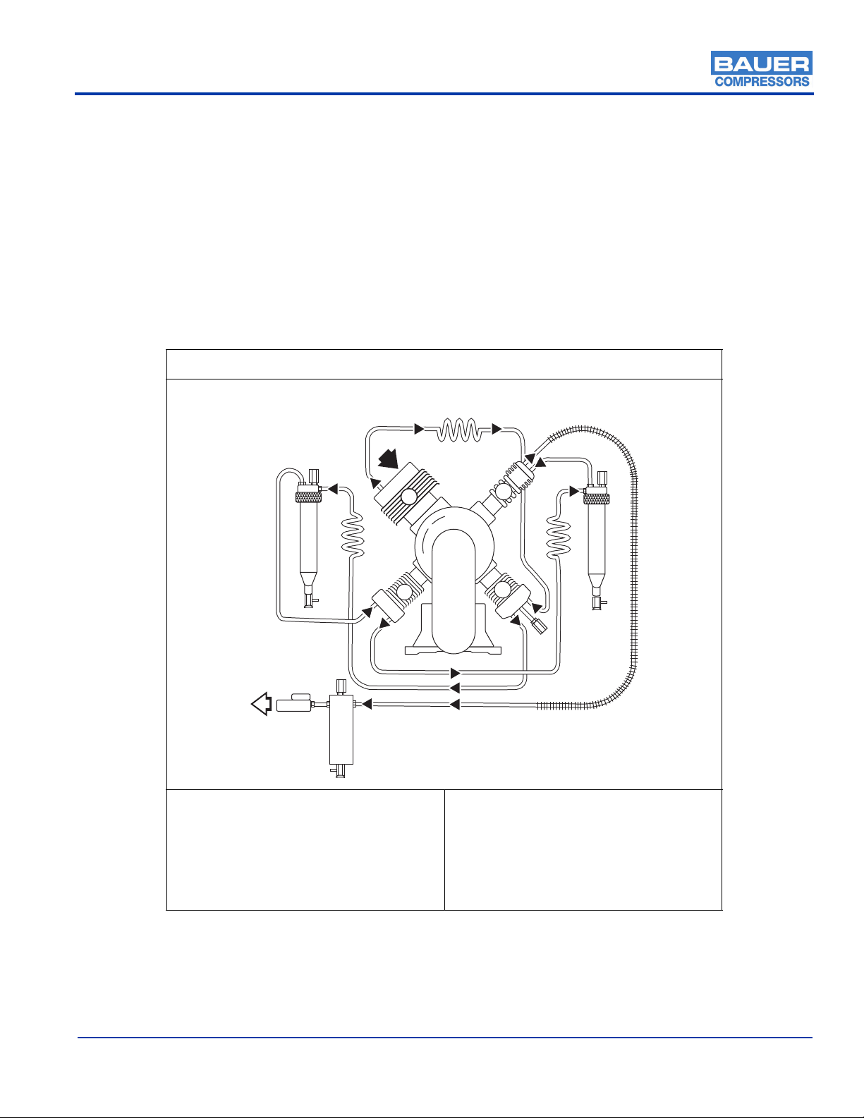
3.1.1.1 Air Flow Diagram
Figure 3.1-1 Four Stage Compressor Air Flow
1. Intake Manifold
2. 1st Stage Cooler
3. 2nd Stage Cooler
4. 3rd Stage Cooler
5. Aftercooler
6. 2nd Stage Separator
7. 3rd Stage Separator
8. Final Separator
9. Manual Condensate Drain Valve
10. Safety Valves
11. Pressure Maintaining Valve (PMV)
12. Compressed Air Outlet
I
III
IV
II
1
2
34
10
6
9
1011
1
28
9
5
7
10
9
10
MNL- 0345
Page 16 Section 3 Base Edition
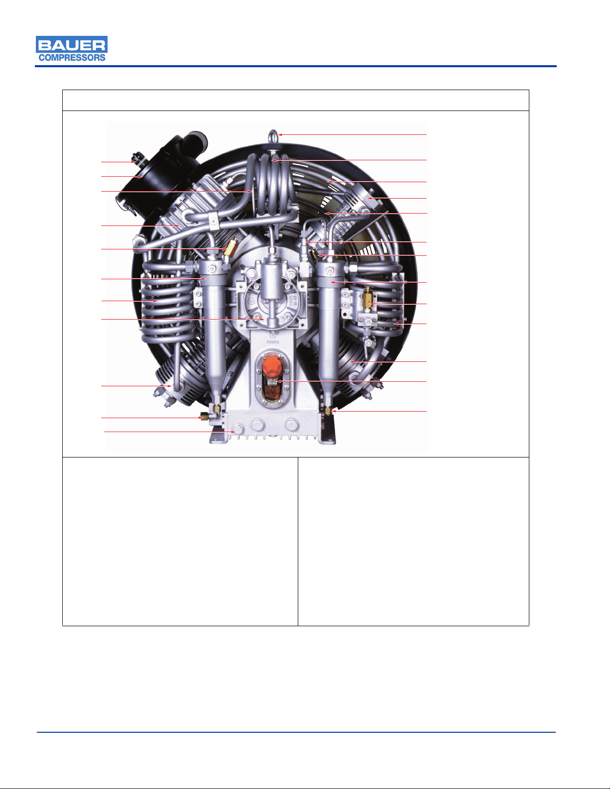
3.1.1.2 Component Location
Figure 3.1-2 Compressor Block (Front View)
1. Service Indicator
2. Intake Filter
3. Crankcase Vent Feedback Line
4. 1st Stage Cylinder
5. 2nd/3rd Inter Stage Pressure Valve
6. 2nd Stage Separator
7. 2nd Stage Cooler
8. Oil Pump Housing
9. 3rd Stage Cylinder
10. Compressed Air Outlet
11. Oil Drain Plug
12. Lifting Eyebolt
13. 1st Stage Auxiliary Cooler (IK180II Only)
14. 1st Stage Inter Cooler
15. 4th Stage Cylinder
16. 4th Stage After Cooler
17. Oil Pressure Regulating Valve
18. 3rd/4th Inter Stage Pressure Valve
19. 3rd Stage Separator
20. 1st/2nd Inter Stage Pressure Valve
21. 3rd Stage Cooler
22. 2nd Stage Cylinder
23. Oil Filler with Sight Glass
24. Condensate Outlet
1
2
3
4
5
6
7
8
9
10
12
11
13 (IK180II Only)
14
15
16
17
18
19
20
21
22
23
24

MVT26
October 2003 Section 3 Page 17
3.1.2 Lubrication System
3.1.2.1 Description.
The compressor is provided with forced-feed lubrication. The oil pressure is produced by a low revving
gear pump. The oil pressure is between 44 psi and 87 psi (3 to 6 bar).
(See Figure 3.1-3). The oil pump (1) is coupled to and driven by the crankshaft. It pumps oil from the
crankcase through an oil filter (2) and the oil pressure regulating valve (3) to the 4th stage cylinder. The
oil is then distributed by the guide piston of the 4th stage and lubricates all the moving parts of the com-
pressor block. The oil pressure sensor (5) allows mounting for an optional oil pressure gauge or electronic
pressure monitoring.
CAUTION
This oil pump must be operated in the correct direction of rotation, other wise no oil pressure will
be built up and the compressor may be damaged.
Figure 3.1-3 Lubrication Oil System
1. Oil Pump
2. Oil Filter
3. Oil Pressure Regulating Valve
4. Injection Line to 4th Stage
5. Oil Pressure Sensor
1
2
3
4
5

MNL- 0345
Page 18 Section 3 Base Edition
3.1.2.2 Oil Level Check
(See 3.1-4). Check the oil level at the oil filler sight gauge on the compressor block every day before put-
ting the compressor into operation. Oil level must never be below the minimum mark molded into the
sight gauge as this will cause severe damage due to lack of lubrication.Overfilling is prevented by the
design of the filler neck; i.e. oil should be filled right to the edge of the opening
3.1.2.3 Oil Change Interval
The synthetic oil should be changed every 2,000 operating hours or biennially, whichever is reached first.
3.1.2.4 Oil Capacity
The oil capacity is approximately 6.5 quarts (6.0 liters). The amount of oil between the minimum and
maximum marks is approximately 1.7 quarts (1.6 liters).
3.1.2.5 Oil Change
1. Run the compressor until it is warm.
2. Remove cap from Oil Filler Sight Gauge.
3. (See 3.1-2) Open the Oil Drain Plug. (11)
4. (See Figure 3.1-5). Remove two bolts (1) with a 13mm wrench. Remove cover (2).
5. (See Figure 3.1-6). Remove the Oil Filter (1) from the rubber gasket at the cover.
6. Mount a new filter element and replace and fasten cover.
7. Fill new oil through filler neck to the Maximum mark on the Oil Fill Sight Gauge.
8. Pour oil in slowly, wait a few minutes until the level settles then replace cap in the Oil fill Sight
Gauge.
9. Return the unit to operation.
Figure 3.1-4 Oil Filler Sight Gauge
CAUTION
Replace the oil filter at every oil change, otherwise when the filter becomes clogged a bypass valve
opens and the oil circulates without being filtered.
Ma
x
Min
MVT26
October 2003 Section 3 Page 19
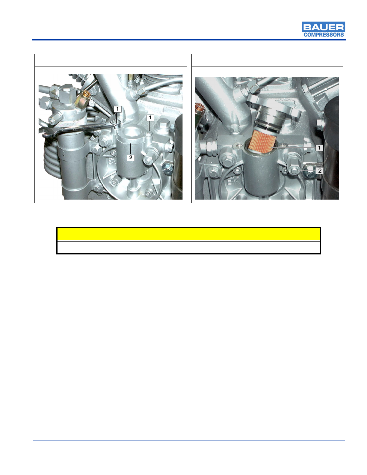
3.1.2.6 Venting the Oil Pump
(See 3.1-6). If after the start of the compressor no oil pressure builds up, venting the oil pump may be
necessary, especially after maintenance and repair work. It may also be necessary if the unit has been
operated in the wrong direction of rotation.
1. With the unit running, open the condensate drain valves.
2. Open Oil Pump Vent Plug (2) and wait until oil comes out bubble free.
3. Replace Oil Vent Plug.
Figure 3.1-5 Removing the Oil Filter Cover Figure 3.1-6 Replacing the Oil Filter
CAUTION
To avoid damage after maintenance the following measures should be strictly adhered to.
This manual suits for next models
1
Table of contents
Other Bauer Compressors Air Compressor manuals


Popular Air Compressor manuals by other brands


DeWalt
DeWalt D55270-1 instruction manual

Parkside
Parkside PKZ 180 B2 Translation of the original instructions

Hitachi
Hitachi WHP09500AEDPC9EQ instruction manual

Champion
Champion CCE10 Operation maintenance manual & parts list

Mangar
Mangar Airflo 12 User instructions

GreenWorks
GreenWorks 4101302 user manual


