Baxi SB-4X Series User manual

6%; 6%;
6%; 6%;
6%; 6%;
6%; 6%;
6%; 6%;
4 232 637-Ed.01/2019-04

Fig. 1: Fig. 2:
Fig. 3: Fig. 4:

Fig. 5: Fig. 6:
Fig. 7a: Fig. 7b:

Fig. 7c: Fig. 7d:
Fig. 7e: Fig. 8:

English
1 Safety
1.1
About these instructions
Read through these instructions completely before installa-
tion. Non-observance of these instructions can result in
injury to persons and damage to the pump/unit.
Once installation work is complete, pass the instructions on
to the end user.
Keep the instructions near the pump. They can be used as
a reference if problems occur later.
We accept no liability for damages resulting from failure to
follow these instructions.
1.2
CE Declaration of Conformity
The design and operation of this product conform to the
applicable European directives and supplementary national
requirements. Conformity has been demonstrated.
The Declaration of Conformity can be viewed at
www.baxi.es or alternatively can be requested from
your local BAXI sales office.
1.3
Safety information
Important safety information is indicated as follows:
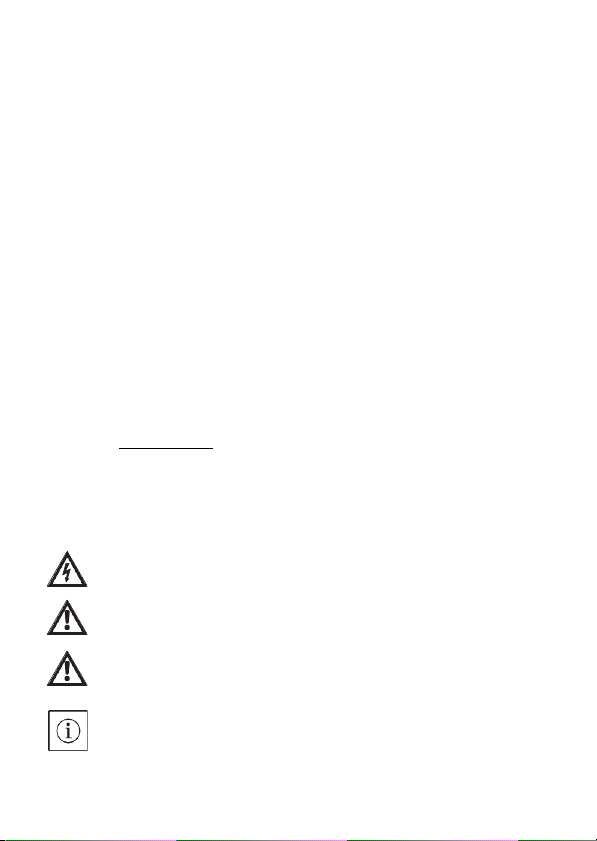
DANGER: Indicates a danger to life due to electrical current.
WARNING: Indicates a possible danger to life or injury.
CAUTION: Indicates possible risks to the pump or other
items.
NOTE: Highlights tips and information.
11

English
1.4
Qualification
The pump may only be installed by qualified personnel.
This product may not be commissioned or operated by per-
sons with insufficient accountability (including children) or
who do not possess the relevant specialist knowledge.
Exceptions are only permitted on appropriate instruction
from safety-responsible persons. The electrical connection
may only be established by a qualified electrician.
1.5
Regulations
The current versions of the following regulations must be
observed when installing the equipment:
•
Accident prevention regulations
•
Worksheets
•
Other local regulations
1.6
Conversion, spare parts
The pump must not be technically modified or converted. It
is not permitted to open the pump motor by removing the
plastic lid. Only use original spare parts.
1.7
Transport
Unpack and check the pump and all accessories upon
receipt. Report any damage sustained in transit immedi-
ately.
Dispatch the pump in the original packing only.
1.8
Electrical current
There is a danger of an electric shock when working with
electrical current. Therefore:
12

English
•
Switch off the power before beginning work on the pump
and make sure that it cannot be switched on again acciden-
tally.
•
Do not kink or nip the power cable or allow it to come into
contact with heat sources.
•
The pump is protected against drips in accordance with
protection class IP 42. Protect the pump against water
spray. Do not immerse in water or other fluids
2 Technical Data
2.1
Type key
SB-4X Series:
Standard secondary hot water circulation pump, glandless
pump with check valves
2.2
Connections (Fig. 1)
SB-4X
Screwed connection: 15 (Rp ½") and check valves
13

English
2.3
Data
SB-4X
Mains voltage
1 ~ 230 V / 50 Hz
Protection class
IP 42
Nominal diameter of connecting
pipes
R ½
Installation length
84 mm (Type A/C: 138 mm)
Max. permissible operating pres-
sure
10 bar
Permitted fluid temperature
range
+2°C to +65 °C
in short-term operation to 2 hours 70 °C
Max. ambient temperature +40 °C
Max. permitted hardness in sec-
ondary hot water circulation sys-
tems
36° fH
See name plate or catalogue for further information.
2.4
Scope of delivery
•
Pump
•
Thermal insulation shell
•
Sealing rings
•
Connector
•
Installation and operating instructions
3 Principle of operation
3.1
Application
This circulator is suitable for drinking water only.
14

English
3.2
Functions (Fig. 2)
Valves
The SB-4X is equipped with a non-return valve (1) on the
pressure side and with a stop valve (2) on the suction side.
When exchanging the motor head (3), it is sufficient to cut
the power by unplugging the connector (5) and to close the
stop valve at the rotating slot (4). The motor head can then
be simply unscrewed → Page 16.
4 Installation and electrical connection
4.1
Mechanical Installation
DANGER: Before starting work, make sure that the pump
has been disconnected from the power supply.
Installation site (Fig. 3)
Provide a weatherproof, frost-free, dust-free and well-venti-
lated room for the installation.
Choose an installation site that is easily accessible.
CAUTION: Dirt can cause the pump to fail. Flush the pipe
system before installation.
NOTE: The stop valve and non-return valve are pre-
installed.
1.
Prepare the installation site so that the pump can be
installed without being exposed to mechanical
stresses.
15

English
2.
Choose the right installation position - only as shown in
(Fig. 3 A). The arrow on the back of the housing indi-
cates the direction of flow.
Turn the motor head or remove it (Fig. 4)
3.
Release the union nut - unscrew it completely if neces-
sary.
CAUTION: Do not damage the housing seal.
Replace damaged seals.
4.
Turn the motor head so that the connector points down-
wards.
CAUTION: If the position is wrong, water can penetrate and
destroy the pump.
5.
Tighten the union nut again.
Open the stop valve (Fig. 5)
6.
Turn slot (1) with a screwdriver so that it is parallel to
the direction of flow.
NOTE: To close, turn the slot so that it is across the direc-
tion of flow.
7.
Fit the thermal insulation shell.
CAUTION: The plastic parts of the motor may not be heat-
insulated in order to protect the pump from overheating.
Connecting (Fig. 6)
8.
Connect the pipework.
16

English
CAUTION: For the versions with stop and non-return
valves, these are already pre-installed and sealed with a
tightening torque of 15 Nm (hand-tight). Screwing with
excessive tightening torque destroys the valve screw con-
nection and the O ring. When installing the valve, use a
fixed spanner to prevent twisting.
4.2
Electrical connection
DANGER: Only a qualified electrician is allowed to work on
the electrical connection. Before establishing the connec-
tion, make sure that the connecting cable is dead.
Establish the electrical connection as follows:
(Fig. 7a - Fig. 7e)
Open the connector as follows: (Fig. 8)
4.3
Filling and venting
1.
Fill the system
2.
The pump rotor space vents automatically after a short
time in operation. This may cause noises. If necessary,
switch off and on repeatedly to accelerate the bleeding.
Dry running for short periods will not harm the pump.
17

English
5 Maintenance/faults
Cleaning
Clean the outside of the pump with a slightly damp cloth
only. Do not use detergents.
Replacing the motor head
WARNING: When removing the motor head or pump, hot
fluid may spurt out under high pressure. Allow the pump to
cool down beforehand.
Close the stop valves before removing the pump
→ Page 16.
NOTE: When the motor is removed and running, noises
and a change in rotation may occur. This is normal for this
situation.
Faultless operation can only be guaranteed when the pump
is operated in fluid.
Replacing the motor head → Page 16.
Order the service motor from a specialist retailer.
18

English
Faults
Causes
Remedies
Pump does not
start.
Interruption in the power
supply, short- circuit or
defective fuses.
Have the power supply
checked by a qualified
electrician.
Motor is blocked, e.g. by
deposits from the water
mains.
Have the pump
removed by a qualified
technician → Page 16.
Check that the impeller
can move by turning it
and rinse out the dirt
that has accumulated.
Pump is mak-
ing noises.
Motor scraping, e.g.
through deposits from
the
water mains.
Running dry, too little
water.
Check the check
valves, they must be
fully open.
Air in the pump.
Switch the pump on/off
5 times for 30 s in each
case.
NOTE: If you cannot remedy the fault, contact a specialist
retailer.
6 Disposal
Damage to the environment and risks to personal health
are avoided by the proper disposal and appropriate recy-
cling of this product.
•
Use public or private disposal organisations when dispos-
ing of the entire product or part of the product.
•
For more information on proper disposal, please contact
your local council or waste disposal office or the supplier
from whom you obtained the product.
19

Français
1 Sécurité
1.1
A propos de cette notice
Lire cette notice dans son intégralité avant l'installation. Le
non-respect de cette notice peut provoquer des blessures
graves ou des dommages au niveau de la pompe.
Transmettre la notice à l'utilisateur final après le montage.
Conserver la notice à proximité de la pompe. Elle sert de
référence en cas de problèmes ultérieurs.
Nous déclinons toute responsabilité en cas de dommages
dus au non-respect de cette notice.Signalisation des
consignes de la notice.
1.2
Déclaration CE de conformité
La construction et le fonctionnement de ce produit répon-
dent aux directives européennes correspondantes ainsi
qu'aux conditions nationales complémentaires.
La conformité a été prouvée. La déclaration de conformité
est disponible sur Internet à l 'adresse www.baxi.es ou
auprès de votre agence BAXI compétente.
1.3
Consignes d'avertissement
Les consignes importantes de sécurité sont représentées
comme suit :
DANGER : Indique un danger de mort dû au courant élec-
trique.
AVERTISSEMENT : Indique un risque potentiel de mort ou
de blessures.
ATTENTION : Indique des dangers potentiels pour la
pompe ou d'autres objets.
REMARQUE : Donne des conseils et des informations.
20

Français
1.4
Qualification
Le montage de la pompe doit être effectué uniquement par
du personnel qualifié. Ce produit ne doit pas être mis en
marche ni être utilisé par des personnes dont la responsa-
bilité de leurs actes est limitée (enfants compris) ou sans
connaissances techniques correspondantes.
Des exceptions sont permises uniquement en suivant les
instructions correspondantes des personnes responsables
de la sécurité. Le branchement électrique doit uniquement
être effectué par un électricien qualifié.
1.5
Prescriptions
Respecter lors de l'installation les dernières prescriptions
en vigueur :
•
Prescriptions de prévention des accidents
•
Fiche du travail
•
Autres prescriptions locales
1.6
Modification, pièces de rechange
La pompe ne doit pas être modifiée ni transformée d'un
point de vue technique. Il est interdit d'ouvrir le moteur de
la pompe en retirant le couvercle en plastique. Utiliser uni-
quement des pièces de rechange d'origine.
1.7
Transport
Dès réception de la pompe, déballer et contrôler toutes les
pièces des accessoires. Signaler immédiatement les dom-
mages dus au transport. Envoyer la pompe uniquement
dans son emballage d'origine.
1.8
Courant électrique
L'utilisation d'électricité peut provoquer un choc électrique.
En conséquence :
21

Français
•
Couper le courant avant toute manipulation avec la pompe
et la sécuriser contre toute remise sous tension.
•
Ne pas plier ni coincer le câble électrique ou éviter qu'il ne
rentre en contact avec des sources de chaleur.
•
La pompe est protégée contre les gouttes d'eau selon
l'indice de protection IP 42. Protéger la pompe contre les
projections d'eau et ne pas la plonger dans l'eau ou
d'autres liquides.
2 Caractéristiques techniques
2.1
Dénomination
SB-4X Gamme :
Circulateur d'eau chaude sanitaire standard, pompe à rotor
noyé avec vannes d'arrêt
2.2
Raccordements (Fig. 1)
SB-4X
Raccord fileté : 15 (Rp ½") et vannes d'arrêt
22

Français
2.3
Données
SB-4X
Tension d'alimentation
monophasé 230 V / 50 Hz
Indice de protection
IP 42
Diamètre nominal des tuyaux de
raccordement
R ½
Longueur de construction
84 mm (type A/C: 138 mm)
Pression de service max. autorisée 10 bars
Plage de température admissible
du fluide
+2°C à +65 °C, en service temporaire
jusqu'à 2 heures +70 °C
Température ambiante max. +40 °C
Dureté d'eau max. dans les sys-
tèmes de bouclage d'eau chaude
sanitaire
36° fH
Pour d'autres données, cf. la plaque signalétique ou le catalogue.
2.4
Etendue de la fourniture
•
Pompe
•
Coquille d'isolation thermique
•
Bagues d'étanchéité
•
Connecteur
•
Notice de montage et de mise en service
3 Mode de fonctionnement
3.1
Application
Ce circulateur convient seulement pour l'eau potable.
23

Français
3.2
Fonctions (Fig. 2)
Soupapes
Le SB-4X sont équi- pées côté refoulement d'un clapet
anti-retour (1) et côté aspiration d'une vanne d'arrêt (2).
Pour remplacer la tête du moteur (3), il suffit de débrancher
le Connector (5) en le retirant et de fermer la vanne d'arrêt
au niveau de l'orifice rotatif (4). La tête du moteur peut
ensuite être dévissée simplement → Page 25.
4 Installation
4.1
Installation mécanique
DANGER : S'assurer avant le début des travaux que la
pompe a bien été séparée de l'alimentation électrique.
Lieu de montage (Fig. 3)
Pour le montage, prévoir une pièce bien ventilée, protégée
contre les intempéries, la poussière et le gel. Choisir un lieu
de montage facile d'accès.
ATTENTION : La saleté peut rendre la pompe inopération-
nelle. Avant le montage, rincer le circuit hydraulique.
REMARQUE : La vanne d'arrêt et le clapet anti-retour sont
prémontés.
1.
Préparer le lieu de montage de sorte que la pompe
puisse être montée sans tensions mécaniques.
2.
Choisir la bonne position de montage comme indiqué
sur la (Fig. 3 A). La flèche sur la face arrière du corps
indique le sens d'écoulement.
24

Français
Tourner ou retirer la tête du moteur (Fig. 4)
3.
Desserrer le manchon et le dévisser entièrement si
nécessaire.
ATTENTION : Ne pas endommager le joint du corps.
Remplacer les joints endommagés.
4.
Tourner la tête du moteur de sorte que le connector soit
placé vers le bas
ATTENTION : En cas de position incorrecte, de l'eau peut
s'infiltrer et détruire la pompe.
5.
Resserrer le manchon.
Ouvrir la vanne d'arrêt (Fig. 5)
6.
Tourner l'orifice (1) à l'aide d'un tournevis de sorte qu'il
soit parallèle au sens d'écoulement.
REMARQUE : Pour fermer, placer l'orifice en diagonale
par rapport au sens d'écoulement.
7.
Placer la coquille d'isolation thermique.
ATTENTION : Les pièces en plastique du moteur ne doi-
vent pas être équipées d'isolation thermique pour protéger
la pompe contre toute surchauffe.
Raccorder (Fig. 6)
8.
Raccorder les tuyaux.
ATTENTION : Pour les versions avec clapet anti-retour et
vanne d'arrêt, ils sont déjà prémontés de manière étanche
avec couple de serrage de 15 Nm (à la main). Un couple de
serrage trop élevé lors du vissage détruit le raccord fileté de
la soupape et le joint torique. Lors du montage, bloquer la
soupape avec une clé à fourche contre toute torsion !
25

Français
4.2
Raccordement électrique
DANGER : Des travaux sur le raccordement électrique doi-
vent uniquement être exécutés par un électricien qualifié.
S'assurer avant le branchement que la ligne de raccorde-
ment est hors tension.
Effectuer le raccordement électrique comme suit :
(Fig. 7a - Fig. 7e)
Ouvrir le connector comme suit : (Fig. 8)
4.3
Remplissage et purge
1.
Remplir l'installation.
2.
La chambre du rotor de la pompe se purge automati-
quement après une courte durée de fonctionnement. A
ce moment-là, des bruits peuvent survenir. Le cas
échéant, un démarrage et un arrêt répétés peut accé-
lérer la purge. Un fonctionnement à sec de courte
durée n'endommage pas la pompe.
26
Table of contents
Languages:
Other Baxi Water Pump manuals
Popular Water Pump manuals by other brands

Graco
Graco 226-249 Instructions-parts list

GÜDE
GÜDE GS 7502 PI Translation of the original instructions

BUSCH
BUSCH COBRA NC 1500 B Installation and maintenance instructions

Franklin Electric
Franklin Electric Little Giant WRS-8E manual

Graco
Graco Xtreme 24N976 Instructions - parts

Barnes
Barnes BAFEZ-1.25x2 Installation and operation manual