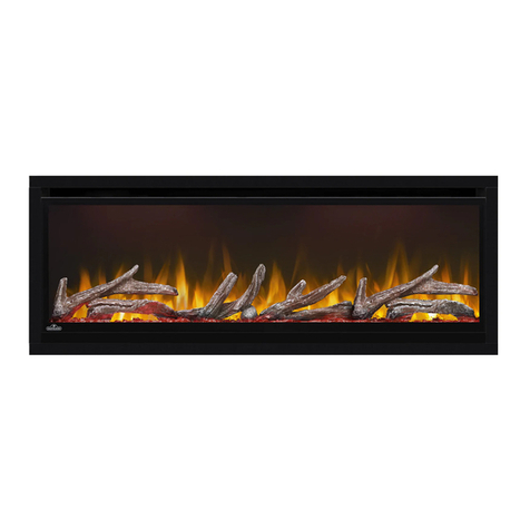
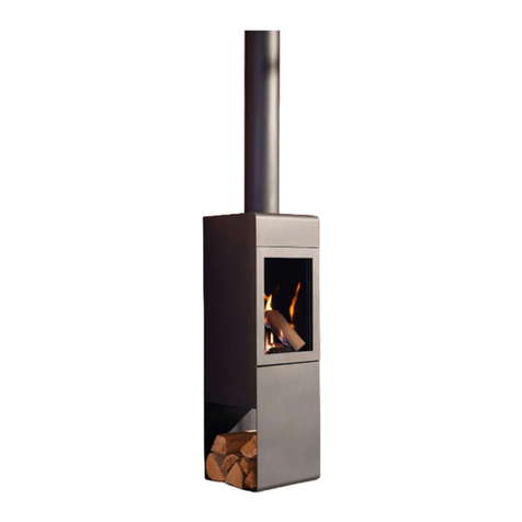
Bayside Furnishings WINWMFP User manual

THIS INSTRUCTION BOOKLET CONTAINS IMPORTANT SAFETY INFORMATION.
PLEASE READ AND KEEP FOR FUTURE REFERENCE.
Bayside Furnishings®Page 1 Factory No. 16366
Date 2014-08-30 Rev. 3 Factory: ZHOPAI
Wintercrest Wall Mount Fireplace
Model # WINWMFP
ADULT ASSEMBLY REQUIRED
If you have any questions regarding assembly or if parts are missing, DO NOT return this item to
the store where it was purchased. Please call our toll-free customer service number and have
your instructions and parts list ready to provide the model name, part name or factory number:
877-494-2536
Pacific Standard Time: 8:30 a.m. - 4:30 p.m., Monday - Friday
Or visit our website www.baysidefurnishings.com
Or e-mail your request to: parts@baysidefurnishings.com
LOT NUMBER:
DATE PURCHASED: / /

Bayside Furnishings®Page 2 Factory No. 16366
When using electrical appliances, basic precautions should always be followed to reduce
the risk of fire, electrical shock and injury to persons, including the following:
1. Read all instructions before using this fireplace.
2. This heater is hot when in use. To avoid burns, do not let bare skin touch hot surfaces. If
provided, use handles when moving this heater. Keep combustible material, such as furniture,
pillows, bedding, papers, clothes and curtains at least 3 feet (0.9 meters) from the front of the
heater and keep them away from the sides and rear.
3. Extreme caution is necessary when any heater is used by or near children or invalids and
whenever the heater is left operating and unattended.
4. Always unplug heater when not in use.
5. Do not operate any heater with a damaged cord or plug or after the heater malfunctions, has
been dropped or damaged in any manner. Return heater to authorized service facility for
examination, electrical or mechanical adjustment, or repair.
6. Do not use outdoors.
7. This heater is not intended for use in bathrooms, laundry areas and similar indoor locations.
Never locate heater where it may fall into a bathtub or other water container.
8. Do not run power cord under carpeting. Do not cover power cord with throw rugs, runners, or
the like. Arrange power cord away from traffic area and where it will not be tripped over.
9. To disconnect heater, turn controls to off, then remove plug from outlet.
10. Connect to properly grounded outlets only.
11. Do not insert or allow foreign objects to enter any ventilation or exhaust openings as this may
cause an electric shock or fire, or damage the heater.
12. To prevent a possible fire, do not block firebox air intakes or exhaust in any manner. Do not
operate firebox on soft surfaces, like a bed, where openings may become blocked.
13. A heater has hot and arcing or sparking parts inside. Do not use in areas where gasoline,
paint, or flammable liquids are used or stored.
14. There is a thermostat limiter inside the heater. When the inner temperature over heating or
occur abnormal heating, the thermostat protective device would cut off power supply to avoid
the fireplace damaged or risk of fire.
15. Use this heater only as described in this manual. Any other use not recommended by the
manufacturer may cause fire, electrical shock, or injury to persons.
16. Always plug heaters directly into a wall outlet/receptacle. Never use with an extension cord or
reloadable power tap (outlet/power strip).
IMPORTANT SAFETY INSTRUCTIONS
There are no user serviceable parts inside the fireplace/heater. If the
unit appears to malfunction, turn the unit off and unplug the unit from the wall immediately,
then contact our Customer Service at 877-494-2536 for assistance, or refer service to
q
ualified service
p
ersonnel.
SAVE THESE INSTRUCTIONS
While the heater is in use, the bottom center of the fireplace can get hot to the
touch, and may cause serious injury or burns. Always supervise small children
around the fireplace/heater. Do not place any cloth or decorations over the heater
outlet of the fireplace, or otherwise obstruct the heater outlet of the fireplace, as
this may cause a fire and serious injury may result.
CAUTION
HOT

Bayside Furnishings®Page 3 Factory No. 16366
This product must be grounded. If it should malfunction or breakdown, grounding provides a path
of least resistance for electric current to reduce the risk of electric shock. This product is
equipped with a cord having an equipment-grounding conductor and a grounding plug. The plug
must be plugged into an appropriate outlet that is properly installed and grounded in accordance
with all local codes and ordinances.
This heater is for use on 120 volts circuit and has a
grounded plug that looks like the one illustrated on
Figure 1. See Figure 1 for grounding instruction. An
adapter as shown at C is available for connecting
three-blade grounding type plugs to two-slot
receptacles. The green grounding lug extending
from the adapter must be connected to a permanent
ground such as a properly grounded outlet box. The
adapter should not be used if a three-slot grounded
receptacle is available.
NOTE: This equipment has been tested and found to comply with the limits for a Class B digital device,
pursuant to Part 15 of the FCC Rules. These limits are designed to provide reasonable protection against
harmful interference in a residential installation. This equipment generates, uses, and can radiate radio
frequency energy and, if not installed and used in accordance with the instructions, may cause harmful
interference to radio communications. However, there is no guarantee that interference will not occur in a
particular installation. If this equipment does cause harmful interference to radio or television reception,
which can be determined by turning the equipment off and on, the user is encouraged to try to correct the
interference by one or more of the following measures:
Reorient or relocate the receiving antenna.
Increase the separation between the equipment and the receiver.
Connect the equipment into an outlet on a circuit different from that to which the receiver is connected.
Consult the dealer or an experienced radio/TV technician for help.
This device complies with Part 15 of the FCC Rules. Operation is subject to the following two conditions:
1) This device may not cause harmful interference, and
2) This device must accept any interference received, including
interference that may cause undesired operation.
Modifications not approved by the party responsible for compliance could void user’s authority to operate
the equipment.
This Class B digital apparatus complies with Canadian ICES-003.
GROUNDING INSTRUCTIONS
Improper connection of the equipment-grounding conductor can result in a
risk of electric shock. Check with qualified electrician or serviceman if you are in doubt as to
whether the product is properly grounded. Do not modify the plug provided with the product – If
it will not fit the outlet; have a proper outlet installed by qualified electrician.
FCC/IC STATEMENT

Bayside Furnishings®Page 4 Factory No. 16366
ELECTRICAL SPECIFICATIONS
HARDWARE LIST
(1) 1/4” x 1-1/4” Bolt (2) Large Lock Washer (3) Large Flat Washer
(6+1 extra) (6+1 extra) (6+1 extra)
(4) 5/32” x 1” Bolt (5) Small Lock Washer (6) Small Flat Washer (7) M3.5 x 20 mm Screw
(4+1 extra) (4+1 extra) (4+1 extra) (8+1 extra)
(8) M4 x 8 mm Screw (9) Large Wall Anchor (10) Small Wall Anchor
(10+1 extra) (4+1 extra) (8+1 extra)
(11) M5 x 50 mm Screw (12) M4 x 20 mm Screw Touch-up Pen
(4+1 extra) (8+1 extra) (1)
Tools required: Phillips screwdriver, Power Drill, Masonry Drill Bit, Hammer and Pencil (not provided).
Model No. WINWMFP
Voltage 120 V
Frequency 60 Hz
Watts 1400 W
Pre-Installation

Bayside Furnishings®Page 5 Factory No. 16366
PARTS LIST
Please read completely through the instructions and verify that all listed parts are present before
beginning assembly.
C- Left Side Rail (1)
A- Wood Front Frame (1) B- Top Rail (1) D- Right Side Rail (1)
E- Left Metal Bracket (1) F- Right Metal Bracket (1) G- Table Top Base (1)
H- Electric Firebox (1) I- Mounting Bracket (1) J- Table Top Support (1)
(Pre-attached on the Firebox H)
K- Front Brace (1) L- Deflector (1) M- Log Set (1)
(Pre-attached on the Firebox H)
N- ‘L’-shaped Bracket (1) O- Decorative Rocks (1) P- Decorative Glasses (1)
(For Flat Wood Frame only)
Q- Cable Channel (2) R- Remote Control with Batteries (1) S- Glass Front (1)
Pre-Installation
(
continued
)

Bayside Furnishings®Page 6 Factory No. 16366
1. Unpack the unit and confirm that you have all the hardware and required parts.
2. Remove the Mounting Bracket (I) from Electric Firebox (H) by unscrewing the two screws that secure
the Mounting Bracket to the top of the Electric Firebox, using a Phillips screwdriver. As shown above.
3. Find the optimal place to mount your Wall-mounted Fireplace. Consider the proper position relative to
your room, placement of furniture and windows.
4. Hold the Mounting Bracket (I) up to the wall to verify the correct location and ensure that the Mounting
Bracket is level. Use a pencil to mark the four mounting holes on the wall at the desired mounting
location, using the Mounting Bracket (I) as a template.
5. With an electric drill (not included) on its low setting, drill 5/16 inch diameter holes to at least 2 inch
deep on the marked points. NOTE: If installing the Mounting Bracket (I) to a wall stud, there is no
need to drill the holes in the wood and no need for the plastic wall anchors. It is recommended to
install the mounting bracket to at least one wooden stud.
Installation – Wall Mount
H
H
I
I

Bayside Furnishings®Page 7 Factory No. 16366
6. Tap 4 Large Wall Anchors (9) into the pre-drilled holes with a Hammer until they are flush with the
wall.
7. Secure the Mounting Bracket (I) to the wall by using four M5 x 50 mm Screws (11). As shown.
8. Hang the Electric Firebox (H) on the hooks at the bottom of the Mounting Bracket (I), and push the
top of the Electric Firebox (H) into the Mounting Bracket. As shown.
9. Ask a friend to hold the Electric Firebox (H) into place and secure it to the Mounting Bracket (I) by
refitting the two small screws which were removed in step 2. As shown.
Installation – Wall Mount
(
continued
)
1
2
I
H
H
H
I
I
9
9
9
9
11
11
11
11

Bayside Furnishings®Page 8 Factory No. 16366
NOTE: We provided the optional Decorative
Rocks (O) and Decorative Glasses (P) for the
ember bed. If the Log Set (M) is not to your
liking, you will need to replace it by following the
steps below.
10. Remove the Log Set (M) from the inset window
ledge at the front of the Electric Firebox (H). As
shown.
11. Arrange the desired Decorative Rocks (O) or
Decorative Glasses (P) along the inset window
ledge.
NOTE: If you choose the Glass Front (S) configuration, continue to step 12. For Wood Front
configuration, skip ahead to the next page.
12. Lift the Glass Front (S) into place, making sure the 2 hooks on the top back of the Glass Front (S) fit
securely into the slots on the top of the Electric Firebox (H). As shown.
NOTE: It is recommended that you use two people at this stage to prevent to the Glass Front (S) or
the Electric Firebox (H).
13. Secure the Glass Front (S) to the Electric Firebox (H) by fastening two M4 x 8 mm Screws (8) on both
sides. As shown.
Installation – Wall Mount
(
continued
)
1
2
1H
S
1
S
H
1
2
H
S
8
HS
or
H
O
P
1
M
2

Bayside Furnishings®Page 9 Factory No. 16366
NOTE: If you have installed the Glass Front (S) on the firebox, disregard the following steps.
14. Locate the Wood Front Frame (A) on a flat and protective surface with the holes facing up.
15. Attach Left and Right Metal Brackets (E and F) over the pilot holes on the wood supports of the Wood
Front Frame (A), using four 20 mm Screws (7) per metal bracket. Fully tighten the screws with a
Phillips screwdriver. As shown above.
16. Align and attach Left and Right Side Rails (C and D) to the Wood Front Frame (A) by inserting six
1-1/4” Bolts (1) with the Large Washers (2 and 3) through the cleat holes and securely screw into
place. As shown above.
Installation – Wall Mount
(
continued
)
A
F
7
E
7
7
7
A
C
D
3
2
1
3
2
1
3
2
1
3
2
1

Bayside Furnishings®Page 10 Factory No. 16366
17. To prevent the Decorative Rocks (O) or Decorative Glasses (P) from falling off, fasten the ‘L’-shaped
Bracket (N) under the bottom curved ledge at the front of the Electric Firebox (H), using three M4 x 8
mm Screws (8). As shown above.
NOTE: Please disregard this step if you choose the Glass Front (S).
18. Lift the Wood Front assembly onto the Electric Firebox (H), making sure the 2 hooks on the top back of
the Metal Brackets (E and F) fit securely into the slots on the top of Electric Firebox (H). As shown.
NOTE: It is recommended that you use two people at this stage to prevent damage to the wood cover
or the Electric Firebox (H).
19. Secure the Metal Brackets (E and F) to the Electric Firebox (H) by fastening two M4 x 8 mm Screws (8)
on both sides. As shown.
Installation – Wall Mount
(
continued
)
1
2
H
E/F
8
H
1
2
1H
A
C
D
1
E/F
H
H
8
8
8
N

Bayside Furnishings®Page 11 Factory No. 16366
20. Position the Top Rail (B) onto the Side
Rails (C and D) to finish the assembly.
21. Separate the arc cover from the Cable Channels (Q).
22. Place the flat side of Cable Channel (Q) where the Cable Channel is to be installed on the wall. Using
the Cable Channel (Q) as a template, mark 4 mounting hole locations with a pencil. Using a 5/16”
masonry drill bit, drill the mounting holes at least 1-1/4" deep at the marked locations.
23. Insert the Small Wall Anchors (10) into the drilled holes and lightly tap them flush with the concrete
surface with rubber mallet or hammer. Securely attach the Cable Channel (Q) over the Small Wall
Anchors (10) in the wall with four M4 x 20 mm Screws (12) and tighten with a Phillips screwdriver.
NOTE: If installing the Cable Channels (Q) to a wooden stud wall, there is no need to drill the holes in
the wood and no need for the plastic wall anchors.
24. Repeat the same process to install the other Cable Channel (Q). Now, route the cables along the Cable
Channels (Q), as shown. With all cables in place, snap the arc cover onto the Cable Channel (Q) to
provide a neat appearance. You can paint the channel to match the wall color, if desired.
A
B
10 12
1-1/4" (32 mm)
QQ
10 12
10
12
10 12
QQ
Installation – Wall Mount
(
continued
)

Bayside Furnishings®Page 12 Factory No. 16366
1. Unpack the unit and confirm that you have all the hardware and required parts.
2. Align and attach the Table Top Support (J) to the Table Top Base (G) by inserting four 1” Small Bolts
(4) with Small Lock Washers (5) and Small Flat Washers (6) through the countersunk holes and
screw into place. As shown. Fully tighten the bolts with a Phillips screwdriver.
3. Fasten the Deflector (L) to the Front Brace (K) with two M4 x 8 mm Screws (8). As shown.
4. Slide the Front Brace assembly onto the Table Top Support (J) and rest it onto the Table Top Base
(G). As shown.
Installation – Table To
p
G
J
6
5
4
6
5
4
K
J
L
8
8
K
J
K
G
G

Bayside Furnishings®Page 13 Factory No. 16366
5. Ask for assistance to position the Electric Firebox (H) onto Table Top Support (J) so that the top
hooks of the Table Top Support (J) properly fit into the bottom slots and the back mounting holes
overlap the threaded sockets on the Electric Firebox (H). As shown above.
6. Insert three M4 x 8 mm Screws (8) through the mounting holes on the Table Top Support (J) and
securely screw into the Electric Firebox (H) by a Phillips screwdriver. As shown.
7. Repeat steps 10 and 11 on the Wall Mount configuration to arrange the desired Decorative Rocks (O)
or Decorative Glasses (P) along the insert window ledge at the front of the Electric Firebox (H).
8. Repeat steps 12 through 19 on the Wall Mount configuration to install the Glass Front (S) or Wood
Front onto the Electric Firebox (H).
Installation – Table To
p
(
continued
)
2
1
J
H
J
H
8
H
J
88

Bayside Furnishings®Page 14 Factory No. 16366
Using the manual and remote controls
On the top right side plate of the Electric Fireplace (H) is the control panel. This panel contains the
buttons to properly operate the electric fireplace. The buttons on the control panel on the side of the
Electric Fireplace (H) and the Remote Control (R) function in the same way. The remote control has an
effective range of up to 13 feet.
Battery Replacement
NOTE: Do not mix old and new batteries.
Do not mix alkaline, standard (carbon zinc), or rechargeable (nicad, nimh, etc.) batteries.
Please always dispose of batteries at a suitable recycling point.
Using the Main Power Button
The main power button (1) is located on the control panel on the right side of the electric fireplace.
Pressing the main power button (1) once turns the power on.
Pressing the main power button (1) again will turn the power off.
If you find that none of the other buttons appear to work, check to make sure that the main power (1) is
turned on.
Using the Flames Control Button
Button Press Flame State Ember Bed Color
1st press ON Amber
2nd press ON Blue
3rd press ON Amber and Blue
4th press ON Color Rotation
O
p
eration
OPEN CLOSE
Press the flames control button (2) to turn on the
ember bed and flame effect.
Pressing the flames control button (2) once turns
flames on and lights the ember bed.
Pressing the flames control button (2) again will
cycle through different colors of the ember bed. The
color rotation mode will cycle through the 3 different
color settings continuously. When using Remote
Control (R), you need to press the button 7 to enter
the color rotation mode. Reference the table for
more detailed information.
Do not ingest batteries.
1. Non-rechargeable batteries are not to
be recharged.
2. Batteries are to be inserted with the
correct polarity.
3. Exhausted batteries are to be removed
from the product. Battery disposal
1. Main Power Button
2. Flames Control Button
3. Heater Control Button
4. Side Light Control Button
5. Timer Function Button
6. Digital Display Unit
7. Color Rotation Button

Bayside Furnishings®Page 15 Factory No. 16366
Using the Heater Control Button
Adjusting the Ambient Side Lighting
Using the Timer Control Button
Pressing the timer control button (5) will set the timer.
This interval period is shown in the display unit (6) on
the control panel on the side of the electric fireplace.
The set intervals are listed in the table.
No Heat Function (Demo Mode)
To turn off the heat mode, press and hold the control panel heater button for 10 seconds to enter heat
lock out mode.
Ember bed lights will flash 6 times to signal the heat function is turned off and locked out.
When the heater button is pressed in lock out mode, the ember bed will flash 6 times until heating
mode is turned on.
To turn on heating mode, press and hold the control panel heater button for 10 seconds, the ember
bed will flash 6 times and the heat function will be restored.
Display Value Temperature Setting
0 64℉/18℃
1 66℉/19℃
2 68℉/20℃
3 70℉/21℃
4 72℉/22℃
5 74℉/23℃
6 76℉/24℃
7 78℉/25℃
8 80℉/26℃
9 82℉/27℃
N ON
Button Press Ember Bed Color
1st press Blue
2nd press Amber
3rd press Amber and Blue
4th press Color Rotation
5th press OFF
Button Press Timer Interval Display Value
1st press 1 Hour 1
2nd press 2 Hour 2
3rd press 3 Hour 3
4th press 4 Hour 4
5th press 5 Hour 5
6th press 6 Hour 6
7th press 7 Hour 7
8th press 8 Hour 8
9th press OFF NONE
O
p
eration
(
continued
)
The heater control button (3) turns the heater on and off.
With the unit ON, press the control panel heater button
(3) for 5 seconds and enter temperature adjustment
mode. In the adjustment mode, the digital indicator (6)
will flash.
Press the control panel heater button (3) to change to
the desired temperature. There are 10 temperature
settings. Reference the table for more detailed
information.
After the temperature is selected, the digital display (6)
will stay on for 10 seconds, then turn off.
Press the side light control button (4) to turn on the
ambient lighting.
To change the color of the lighting press the side
light control button (4) again. You can control the
side lights color as described in the table. The color
rotation mode will cycle through the 3 different color
settings continuously.
NOTE: If this product experiences exceptionally
high temperature, it may automatically stop heating.
If this occurs the product should be unplugged or
isolated from the main supply for a period of 30
seconds before the power is then re-supplied.

Bayside Furnishings®Page 16 Factory No. 16366
The blower motor and flame motor are pre-lubricated for a durable using time and need no further
lubrication or maintenance. To remove any accumulation of dust or fluff the soft brush attachment of a
vacuum cleaner should occasionally be used to clean the outlet grille of the fan heater.
Use a soft, clean cloth that will not scratch the surface when dusting.
Use a clean soft cloth dampened with warm water to clean the fireplace surface. DO NOT use household
or abrasive cleaners, as these products may damage the surface.
When cleaning the glass viewing screen use a non-abrasive damp cloth with liquid cleaner or soft soap
if necessary; DO NOT use cleaning powders or any other substance with abrasives since these
substances will scratch glass.
Under no circumstances should this product be operated with a broken or chipped glass panel.
Do not strike or slam the glass.
In the event that your appliance is stained or otherwise damaged during use, we recommend that you
call a professional to repair your furniture.
When not in use please unplug the cord from the outlet to prevent any damage or accidental plug of the
cord.
ALWAYS DISCONNECT FROM THE POWER SUPPLY BEFORE CLEANING THE
HEATER. FIRST TURN OFF THE MAIN POWER. THEN REMOVE THE ELECTRICAL PLUG FROM THE
WALL OUTLET.
DO NOT USE THIS FIREPLACE INSERT IF ANY PART OF IT HAS BEEN UNDER
WATER. IMMEDIATELY CALL A QUALIFIED SERVICE TECHNICIAN TO INSPECT THE FIREBOX AND
REPLACE ANY PART OF THE ELECTRICAL SYSTEM WHICH HAS BEEN UNDER WATER.
A Touch-up Pen has been provided to repair any small nicks or scratches that may occur during
assembly or shipping.
The Fireplace is now ready for you to enjoy for many years to come.
We hope you enjoy your purchase for many years and thank you for your purchase!
ELECTRIC FIREBOX PARTS LIST
Part Name Part Number
Flame Generator Drive Motor WINWMFP-FGDM
Heater WINWMFP-H
Blower WINWMFP-B
Log Set WINWMFP-LS
Main PCB WINWMFP-MPCB
Control Panel PCB WINWMFP-CPPCB
Flame Light PCB WINWMFP-FLPCB
Side Light PCB WINWMFP-SLPCB
Ember Bed Light PCB WINWMFP-EBLPCB
Remote Control - 6 Buttons WINWMFP-RC
CARE & MAINTENANCE INSTRUCTIONS

Bayside Furnishings®Page 17 Factory No. 16366
We are confident that you will be delighted with your Bayside Furnishings®purchase.
Should this product be defective in workmanship or materials, or fail under normal use, we will repair or
replace it for a period of up to one (1) year from date of purchase. Every Bayside Furnishings®product is
designed to meet your highest expectations. We guarantee that you will immediately see the value of our
fine furniture.
This warranty gives you specific rights and you may also have other rights which vary from State to State.
Customer Service: 877-494-2536
8:30 A.M. to 4:30 P.M., Pacific Time, Monday to Friday
www.baysidefurnishings.com
TROUBLE SHOOTING GUIDE
PROBLEM SOLUTION
1. No power or function.
1a. Check that unit is plugged into a standard
120V outlet.
1b. Press power button on the control panel.
2. Main power switch lights up, but no flame
effect. 2a. Open the top and back panel to check if the
flame spindle has fallen off from spindle motor.
3. Have flame effect, but heater does not blow
warm air.
3a. Confirm temperature setting exceeds room
temperature.
3b. Try to turn on/off HEATER button several
times to make sure it is in the “ON” position.
4. Heater does not work, but Power and Heater
switches are in the “ON” position and
thermostat is set on “HI”.
4a. Turn all switches to the “OFF” position and
unplug the unit from the wall outlet for 5
minutes. After 5 minutes plug the unit back into
wall outlet, and operate as normal.
5. The display unit on the control panel shows
“E” and the function indicator is quick flashing,
indicating it is in alarm mode.
5a. Unplug the unit from the wall outlet for 5
minutes. After 5 minutes plug the unit back into
wall outlet, and operate as normal.
For replacement parts or assistance, call customer service at the above number.
Q
UALITY GUARANTEE

IF YOU NEED TO ORDER ANY REPLACEMENT PARTS, PLEASE USE THE LIST BELOW
Wintercrest Wall Mount Fireplace (WINWMFP)
*WINWMFP-1-WFF Wood Front Frame *WINWMFP-21-1SB 5/32" x 1" Bolt
*WINWMFP-2-WFFG Wood Frame Glass *WINWMFP-22-SLW Small Lock Washer
*WINWMFP-2A-GL Glass Liner *WINWMFP-23-SFW Small Flat Washer
*WINWMFP-3-LSR Left Side Rail *WINWMFP-24-M3.5x20S M3.5 x 20 mm Screw
*WINWMFP-4-RSR Right Side Rail *WINWMFP-25-TUP Touch-up Pen
*WINWMFP-5-LMB Left Metal Bracket *WINWMFP-26-M4x8S M4 x 8 mm Screw
*WINWMFP-6-RMB Right Metal Bracket *WINWMFP-27-LWA Large Wall Anchor
*WINWMFP-7-TR Top Rail *WINWMFP-28-SWA Small Wall Anchor
*WINWMFP-7A-REM Rare Earth Magnet *WINWMFP-29-M5x50S M5 x 50 mm Screw
*WINWMFP-8-TTB Table Top Base *WINWMFP-30-M4x20S M4 x 20 mm Screw
*WINWMFP-9-MB Mounting Bracket *WINWMFP-CHW Complete Hardware for Wood Parts
*WINWMFP-10-D Deflector *WINWMFP-CHF Complete Hardware for Firebox
*WINWMFP-11-FB Front Brace *WINWMFP-FGDM Flame Generator Drive Moto
r
*WINWMFP-12-TTS Table Top Support *WINWMFP-H Heater
*WINWMFP-13-LB L'-shaped Bracket *WINWMFP-B Blower
*WINWMFP-14-CC Cable Channel *WINWMFP-LS Log Set
*WINWMFP-15-GF Glass Front *WINWMFP-MPCB Main PCB
*WINWMFP-16-DR Decorative Rocks *WINWMFP-CPPCB Control Panel PCB
*WINWMFP-17-DG Decorative Glasses *WINWMFP-FLPCB Flame Light PCB
*WINWMFP-18-1 1/4B 1/4" x 1-1/4" Bolt *WINWMFP-SLPCB Side Light PCB
*WINWMFP-19-LLW Large Lock Washer *WINWMFP-EBLPCB Ember Bed Light PCB
*WINWMFP-20-LFW Lar
g
e Flat Washer *WINWMFP-RC Remote Control
g
Table of contents
Other Bayside Furnishings Indoor Fireplace manuals
Popular Indoor Fireplace manuals by other brands

Ambiance Fireplaces
Ambiance Fireplaces FP-36 Installation and operation instructions

Touchstone
Touchstone WS-G-01 owner's manual

Whalen
Whalen Millstead WSF60MS26GAO instruction manual

Charlton & Jenrick
Charlton & Jenrick Paragon Core BF Remote Control owner's manual

Dimplex
Dimplex BLF50 owner's manual

Dimplex
Dimplex ELECTRALOG DF203A troubleshooting guide