BBC Bircher PrimeTec B User manual

1
PrimeTec
PrimeScan
PrimeScan B
a b
a b
1.
2.
*
PrimeTec B
A B C DA B C DA B C D A B C DA B C D
PrimeTec B
PrimeScan B
Combined detector AIR/Radar for opening and protecting automatically controlled sliding doors
Translation of the original instructions
General
1Safety instructions
2.1 Setting the AIR eld width (PrimeTec / PrimeScan)
2Mounting
ENGLISH
267087K
01/19
Hood
AIR light window
Cable bushing
Short Guide
Mounting holes
LED AIR: red (left)
Button function (red)
Button value (black)
LED radar: green (right)
AIR adjustment screw
Radar module
LCD display
a) red LED b) green LED
– Consider the national and international regulations on door safety.
– Only trained, qualied personnel may mount and start up the detector.
– The unit may only be opened and repaired by the manufacturer.
– The unit may only be operated from a safety extra-low voltage (SELV)
system with safe electrical separation.
– Always consider the safety functions of your application as a whole,
never just in relation to one individual section of the system.
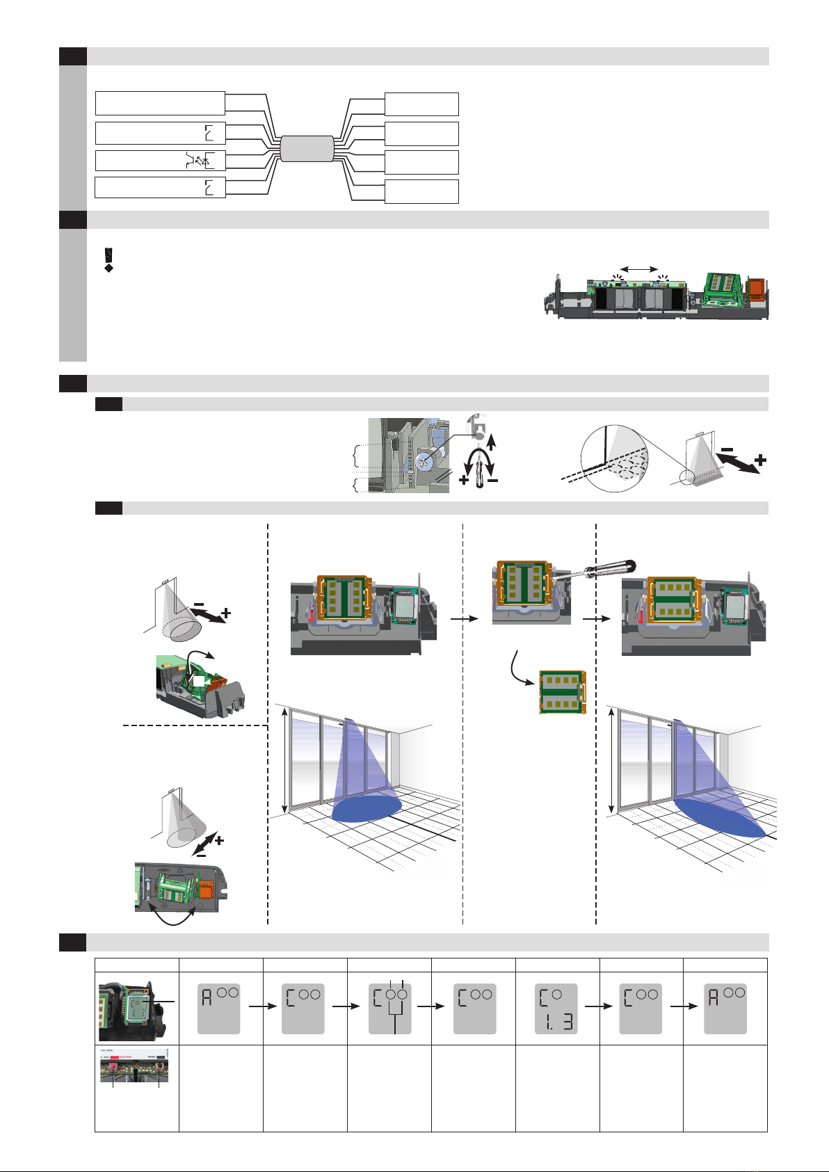
Start-up
Recommended start-up sequence: Mounting Connection Initialisation
Mounting
A, D covered A, C, D covered C, D covered A, B, D covered A, B covered
Field width: 1 x 0.2 m
Field width: 0.5 x 0.2 m
Field width: 1.2 x 0.2 m
Field width: 0.5 x 0.2 m
Field width: 1.2 x 0.2 m
1. Remove cover hood 3. Lay and connect cable
2. Set AIR eld width (see chapter 2.1) 4. Mount detector
The width of the AIR eld can be set using the click-in plastic cover in front of the detector’s lens.
1. Slide
2. Push & click!
– The installer is responsible for carrying out a risk assessment and in-
stalling the detector and the door system correctly.
– Avoid touching any electronic components.
– The door drive and transom prole must be grounded correctly.
Mounting the detector
2.2
Possible settings (Dimensions at 2.2 m mounting hight):
Detector without cover:
All light beams are active
Field width:
2.3 m x 0.2 m
at 2.2 m
1. Position drill template
2. Drill the holes, remove drill template
3. Lay cable and mount detector
* Factory setting
2
1 2 1 2
1 21 2 1 2
0°
+ 1 … + 7°
– 1 … – 5°
–
+
5-10 cm
–
+
–
+
–
–
+
–
+
– +
1m
2m
3m
1m
2m
0m
0m
1m
2m
3m
4m
2.2 m
90°
1m
2m
3m
1m
2m
0m
0m
1m
2m
3m
4m
2.2 m
LCD 1 2 1
PrimeTec B / PrimeScan B
Cable
–
+
–
+
–
+
3 m
–
+
Radar AIR
Power Supply
1 white white
2 brown brown
3 green green
4 yellow
6 pink pink
5 grey grey
yellow
7 blue blue
8 red red
Radar output
Test
11.5 – 32 VDC
Controller
Radar
Test
AIR
AIR output
3Electrical connections
Connecting
Initialisation
4Initialisation
Remove all objects that do not form part of the usual door system environment from the
door area BEFORE switching on the power supply. Ensure that no people are in the door
area, otherwise correct startup will not be possible.
The alternate ashing shows the initialisation (teaching) of the detector. (Duration 20 - 25 seconds).
During startup, the rmware version FXXX is displayed.
Following initialisation, the red/green LED only illuminates when a detection has occurred.
The door system is now operational at this point. If any further settings are required, proceed as described in the following sections.
red LED green LED
5Mechanical ne tuning
5.1 AIR eld (PrimeTec / PrimeScan)
Settings of the inclination angle on the
adjustment screw:
Inclination :
– 5° ... +7° continuously adjustable
5.2 Radar eld (PrimeTec)
Manual settings of the
inclination angle
0° ... +90° in 5° steps
Manual settings of the
pivot angle
– 20° ... +20°in 5° steps
Wide radar eld turn 90° Narrow radar eld
Inclination angle: 35° Inclination angle: 35°
6Conguration using programming buttons (Operator buttons)
Automatic Cong. mode Choose Choose Funct./Parameter Back to choice Back to autom.
Operator buttons
red (Function)
black (Value)
A: Automatic mode
t: Test active
Radar
output on
AIR
output on
Press shortly both
buttons
simultaneously
Red button:
switch
between Radar, AIR
and general
Black button:
choose
Red button:
Choose
parameter *
Black button:
Choose value of the
parameter
Press both
buttons
Press both
buttons
Switches to
automatic mode (A)
automatically after
1 min
* Value is going to be saved by switching to other parameters
min. = 0.5 m x 0.25 m (WxD)
max. = 4 m x 2 m (WxD)
min. = 0.16 m x 0.8 m (WxD)
max. = 2 m x 4 m (WxD)
General
3
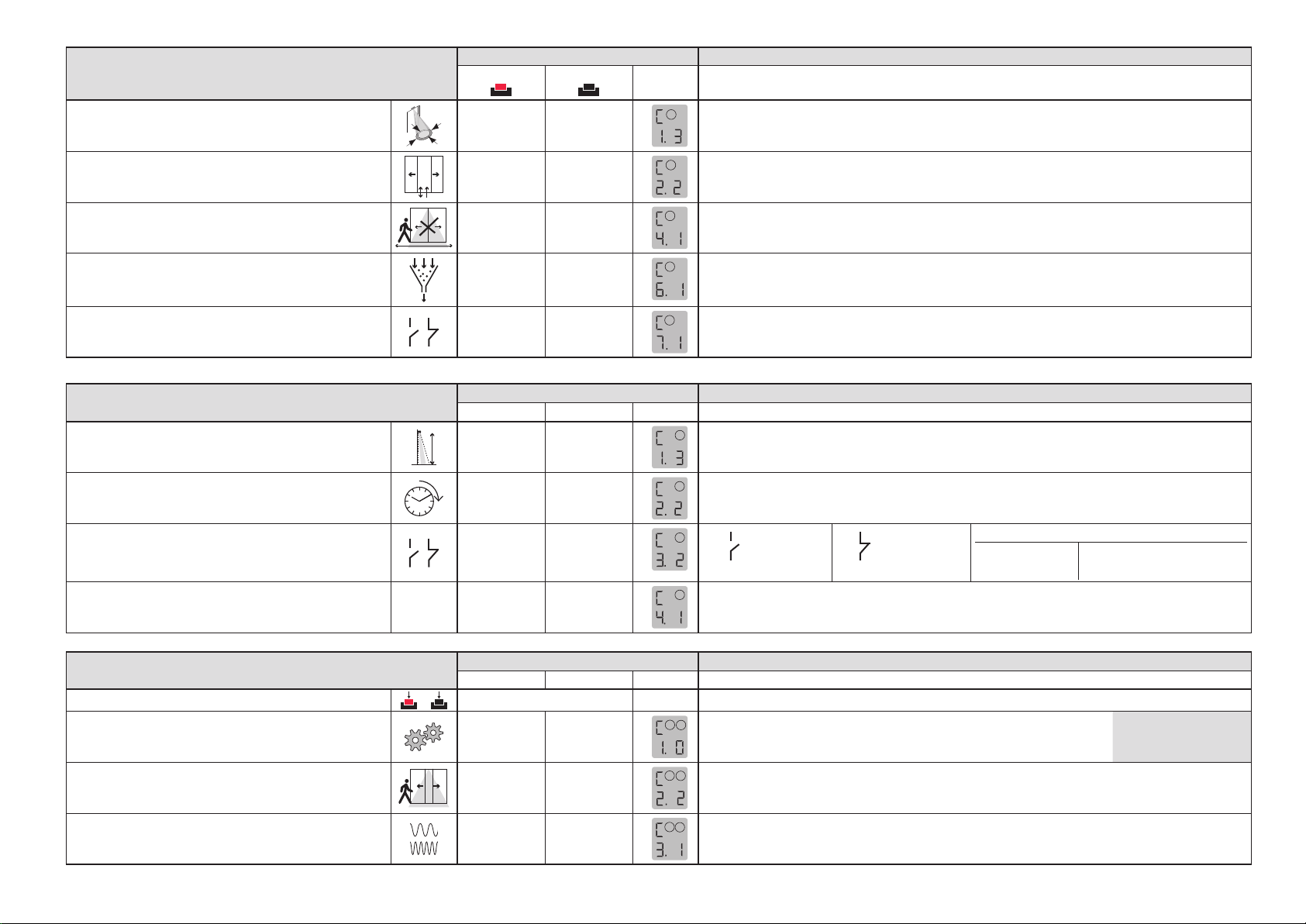
Radar functions (PrimeTec) OPERATION OF THE BUTTONS1DESCRIPTION
Function (red) Value (black) LCD
Field size
1 1 – 5
1 = Smallest radar eld, ......., * = Medium radar eld, ......, = Largest radar eld
Direction recognition
2 1 – 2
1 = both directions
* = forward
Cross Trac Optimisation CTO
41 – 2
1* = Off
= On (recommended only at narrow eld)
Door lter
61 – 2
1* = Filter off, = Door and interference lter on (EMV ows, e.g. uorescence tube)
Radar output
71 – 2
1* = active (NO)
= passive (NC)
The Slow Motion Detection (SMD) is a factory setting. The SMD recognises slow motions after the detecor has been activated.
AIR functions (PrimeTec / PrimeScan) OPERATION OF THE BUTTONS1DESCRIPTION
Function (red) Value (black) LCD
Set sensitivity
1 1 – 5
2 = high sensitivity (acc. to EN 16005 ≤ 3m, only indoors)
= medium sensitivity (acc. to EN 16005 ≤ 3m) = low sensitivity (acc. to EN 16005 ≤ 2.3m)
* = normal sensitivity (acc. to EN 16005 ≤ 2.6m) = very low sensitivity
Set teach-in time
21 – 5
2= 10 s * = 30 s (acc. to EN 16005) = 60 s (acc. to DIN 18650 + AS 5007)
= 180 s = 15 min
AIR output contact logic
31 – 4
2= active (NO)
no detection
contact open
* = passive (NC)
no detection
contact closed
Series connection
Settings
Master ➔ Slave
Master ➔ Slave
Wiring: See series connection diagram:
www.bircher.com ➔
Products ➔ PrimeTec
AIR output
41 – 2
2* = On
= Off (AIR is going to be reactivated automatically after 15 minutes)
General functions (PrimeTec / PrimeScan) OPERATION OF THE BUTTONS1DESCRIPTION
Function (red) Value (black) LCD
Reset
+
Press both buttons 8 seconds Initialisaiton and teaching of the background
Presetting (After presetting and leaving cong. a reset will
be done automatically) 1
1 – 8
Press value for
1 second to change the
presetting
12= Standard, = footpath, = home for the aged, = wind screen,
= high door, = narrow door, = wide door,
= factory settings
For all values set,
parameter 0 is displayed
Combined outputs
activated / not activated 2 1 – 2
12= activated (radar and AIR actuate the radar output)
* = not activated
AIR-frequency (In the case of overlapping AIR elds
consider the addressing order:
➔odd nr. 1 ➔ even nr. 2➔ odd nr. 3)
31 – 6
2
1* = Frequency 1, = Frequency 2, = Frequency 3, = Frequency 4, = Frequency 5,
= Frequency 6
1 Press both buttons shortly for conguration mode *Factory setting

4
Designed in Switzerland / Made in China
BBC Bircher Smart Access, BBC Bircher AG, Wiesengasse 20, CH-8222 Beringen, www.bircher.com
red LED green LED Fault Remedy
not
illuminated
continuously
lit
Radar tripping when door is closing 1. Set angle of radar further away from the door.
2. Adjust radar eld size.
Radar false tripping without
apparent external inuence
1. Avoid light sources (e.g. uorescent tubes) in the immediate vicinity of the detector.
2. No moving objects (plants, advertising posters, etc.) in the vicinity of the detector.
3. Avoid strong vibration at the radar detector
4. Possible inuence from a second radar detector in the vicinity (very unlikely)
continuously
lit
not
illuminated
AIR tripping when door is closing 1. Set angle of AIR detector further away from the door
AIR false tripping without apparent
external inuence
1. Avoid light sources (e.g. uorescent tubes) in the immediate vicinity of the detector.
2. Avoid puddles of water on the ground.
3. Avoid strong vibration at the AIR detector.
4. Inuence of overlapping AIR eld from another detector.
Set new Reglobeam address or CAN bus address.
5. Reduce sensitivity of the AIR (increase value).
not
illuminated
not
illuminated Door stays open 1. Switch AIR exit contact logic to other value
7Remedying malfunctions
8Technical data
7.1 Remedying false tripping
7.2 Remedying detector malfunctions
red LED green LED Fault Remedy
ashing ashing
1
1: Self test (RAM/ROM)
2: Watchdog
1. Disconnect device from supply voltage
2. Restart device
3. If device displays fault again or does not start ➔renew device
ashing not
illuminated
2
5: AIR fault
6: AIR output fault
1. Disconnect device from supply voltage
2. Clean optics-cover and check for scratches
3. Restart device
4. If device displays fault again or does not start ➔renew device
Technology Active infrared (wavelength: 880nm), radar double eld module ➔ PrimeTec (24.125 GHz)
Number of IR spots 24
IR spot dimensions 3 cm x 3 cm (at 2.2 m mounting height)
Response time < 200 ms
Mounting height 1.8 - 4 m
Angle setting of IR spots – 5° ... + 7° continuously adjustable
Power Supply ≤ 120 mA @ 11.5 ... 32 VDC
Power consumption < 4 Watt
Making current ≤ 240 mA
Output (AIR / Radar) Semiconductor relay: max. contact voltage 24 VAC / 34 VDC, max. contact resistance: 10 Ω
max. load current 40 mA, max switching capacity:
500 mW (AC) / 500 mW (DC)
Protection type Suitable for use acc. to IP54
Operating temperature -20° ... 60° C
Dimensionsn PrimeTec: 260 x 60 x 48.5mm (LxWxD), PrimeScan: 216 x 60 x 47.5mm (LxWxD)
Weight PrimeTec: 250g, PrimeScan: 180g
Estimated economic life-time 20 years
9EU Declaration of Conformity
10 WEEE
11 FCC approval
12 Contact
This device meets the requirements of Part 15 of the FCC regulations and the RSS-210 standard of Industry Canada.
Warning: Changes or modications made to this device may void the FCC authorisation to operate this device.
See attachment
Devices with this symbol must be treated separately during disposal. This must be done in accordance with the laws of the
respective countries for environmentally sound disposal, processing and recycling of electrical and electronic equipment.
This manual suits for next models
1


