BBC MB Series User manual

MB SERIES TABLE TOP CONVEYOR DRYER
Assembly Instructions
INDUSTRIES, INC.

2
IMPORTANT INSTRUCTIONS:
materials, and personnel are available for the safe and successful use of the dryer.
BBC Industries, Inc. is interested in the safe operation of its equipment. All wiring to this equipment must
be connected to the electrical source in strict accordance with National Electrical Code (N. E. C.) and local
codes having jurisdiction.
Do not use extension cords to power this equipment.
National Fire Protection Association (NFPA).
Puncture of the element face may result in a shock hazard.
• This heater is hot when in use. To avoid burns, do not let bare skin touch hot surfaces. Keep
combustible materials, such as furniture, pillows, bedding, papers, clothes, etc., away from the dryer.
• Extreme caution is necessary when any dryer is used by or near children or invalids and whenever the
•
inspected by a reputable electrician before reusing.
• Do not use outdoors.
•
• Do not insert or allow foreign objects to enter any ventilation opening as this may cause an electric
shock or fire, or damage to the dryer.
• A dryer has hot and arcing or sparking parts inside. Do not use it in areas where gasoline, paint, or
flammable vapors or liquids are used or stored.
• Use this dryer only as described in this manual. Any other use not recommended by the manufacturer
may cause fire, electric shock, or injury to persons.
RETAIN THIS MANUAL FOR FUTURE REFERENCE
Please review all these instructions prior to assembly.
The BBC MB SERIES Table Top is packaged in four cartons for shipment.

3
TOOLS REQUIRED:
Power Requirements
• (x1) 1/2” wrench • (x1) 7/16” wrench • (x1) Phillips screwdriver • (x1) Needle nose pliers
DO NOT plug the equipment in (or apply power) until instructed to do so.
.
WATTS VOLTS AMPS FREQUENCY PHASE PLUG
1462 12012.18 50/60 HZ 1 NEMA5-15P
IMAGE DESCRIPTION QTY. ITEM #
MB21-002 (LEFT)
CONVEYOR RAIL - TAKEUP 1 1
MB21-002 (RIGHT)
CONVEYOR RAIL - TAKEUP1 2
MB21-003 (LEFT)
CONVEYOR RAIL - MOTOR 1 3
MB21-003 (RIGHT)
CONVEYOR RAIL - DRIVE 1 4
22-141
BUMPER/FOOT 4 5
What’s in the box
/// WARNING ///

4
IMAGE DESCRIPTION QTY. ITEM #
MB21-005
SPLICE CHANNEL2 6
25-025
5/16-18 BOLT 24 7
MB21-022
TAKEUP ROLLER ASSEMBLY 1 8
MB21-023
DRIVE ROLLER ASSEMBLY 1 9
08-252-MB
GEARMOTOR 1 10
25-176
#10-32 x 1/2L SCREW 4 11
18-119
DRIVE CHAIN 1 12
AIR-229
CHAIN COVER1 13
25-001
#6-20 x 3/8L SCREW 36 14
MB21-006
FLOOR PAN 2 15
1804-300
CONVERYOR BELT 1 16

5
IMAGE DESCRIPTION QTY. ITEM #
22-057
ROUTING CLIP 2 17
MB21-014
INNER SIDE PANEL 2 18
MB21-015
INNER ENTRY/EXIT2 19
MB21-018
OUTERSIDE PANEL - CP 1 20
MB21-025
CONTROL PANEL 1 21
MB21-017
OUTERSIDE PANEL 1 22
MB21-020
CHAMBER END CAP 2 23
MB21-024
HEATER ASSY 1 24
MB21-016
INNER CHAMBER COVER 1 25
22-093
4” START COLLAR 1 26
MB21-019
CHAMBER COVER 1 27
MB21-021GRN
CHAMBER CURTAIN - GREEN2 28

6
1. Locate the (4) painted Conveyor Rails (ITEM 1, 2, 3, & 4) from BOX 1 and the (4) rubber Bumper/Feet
(ITEM 5) from BOX 2.
2. Thread each Bumper foot into the threaded insert in each of the rails.
3. Locate the (2) unpainted Splice Channels (ITEM 6) from BOX 1.
4. Using (12) of the 5/16” x .75L black hex bolts (ITEM 7) from BOX 2, assemble the (2) Conveyor Rail
that the Bumper/Feet face the same direction for each rail assembly.
4
6
2
6
1
7
57
53
7
5
5
STEP 1

7
TruTrak™
Belt Guide
5.
6.
roller drum side out.
7. Locate the Takeup Roller Assy (ITEM 8) in BOX 1.
8.
TruTrack™ Belt guide with the guide on the Drive Roller Assy. Note roller drum side out. Tighten the
bolts only finger tight. (The position of this roller will be adjusted later in these instructions).
9. Locate the Drive Gearmotor (ITEM 10) from BOX 3 and the four #10-32 x ½” Machine Screws (ITEM 11)
from BOX 2.
10. Mount the Drive Gearmotor through the mounting slots on the Conveyor Drive Rail with the Sprocket
side toward the roller, as shown in the figure.
11. Thread the four #10-32 Machine Screws into the threaded bosses in the Gearmotor. Do not fully
tighten.
12. Slide the Gearmotor in the slots towards the Conveyor Drive Roller.
7
7
8
9
7
7
Roller Drum
Faces Out
Roller Drum
Faces Out
Finger Tighten
Only
Sprocket to side
withgrommet
installed
STEP 2

8
1/4—1/8 SLACK TOLERANCE
INSERT PLUG
THROUGH HOLE
ONCE THE CHAIN IS INSTALLED, SLIDE THE
MOTOR AWAY FROM ROLLER TO REMOVE SLACK
DO NOT REMOVE ALL SLACK
THEN TIGHTEN SCREWS TO SECURE MOTOR
13. Locate the Roller Chain (ITEM 12) from BOX 2.
14. Seat the Chain around both sprockets. Slide the Gearmotor to remove most of the slack from the
Chain. Allow a small about of slack in the chain per the figure. A tight chain will have a reduced life.
15. Tighten the four Machine Screws.
16. Locate the Chain Cover (ITEM 13) and two #6 x 3/8” Sheet Metal Screws (ITEM 14) from BOX 2.
17. Fit the Chain Cover over the sprockets and chain. Secure with the two Sheet Metal Screws into the pil
ot
18. Insert the Gearmotor cord through the grommet in the Conveyor Rail.
19. Locate the two Floor Pans (ITEM 15) from BOX 2.
20. Place the first Floor Pan on the lower flanges of the Splice Channel (ITEM 4) of the Conveyor Rail
assembly with the flanges down and towards the Rollers.
21. Center the Floor Pan between the Conveyor Rails.
22. Insert the second Floor Pan (flanges down) between the upper flange of the Splice Channel and the
flange of the Conveyor Rail assembly.
23. Center the Floor Pan between the Conveyor rails.
12
Sprocket side
toward roller
Upper oor pan ts
between anges
Before tightening screws,
slide the motor toward
the roller to installthe
chain over both sprockets
14
11
15
10
14
13
STEP 3

9
24. Locate the Conveyor Belt from BOX 3 (ITEM 16).
25. Locate and remove the pin from the teeth at one of the ends of the Conveyor Belt. Do not discard or
bend the pin.
26. Route the Conveyor Belt around both Conveyor Rollers atop both Floor Pans with the rubber Trutrak™
edge guide aligned with the guide slots in the Rollers.
27. Mesh the teeth of the alligator splice. Check to see that the edges of the Belt are best aligned then
reinsert the pin per figure. A pair of pliers may be needed to fully reinsert the pin.
28. Remove much of the slack from the Conveyor Belt by pulling the Takeup Roller Assy (ITEM 8) by hand,
then tighten the 5/16” Hex Bolts. The Conveyor Belt only needs to be tight enough so as not to slip
while in use. Over tightening the Conveyor Belt may lead to reduced life.
29. Locate the Routing Clip (ITEM 17) from BOX 2.
30. Wrap the Clip around the Gearmotor cord and insert it into the ¼” hole in the Conveyor Drive Motor
Rail.
16
8
Loosen bolts and slide
after installation of
Conveyor Belt
Pin shipsare installed in one end
of the conveyor belt. Remove and
DO NOT bend. Meshteethand
reinsert. Pliers may be needed.
Be sure edges are aligned or Conveyor Belt
may jump out of the Trutrak™ Belt grove
TruTrak™
Belt guide must
be between disks
(both ends)
After the pin is re-inserted, slide the
roller back until the belt is hand tight.
Tighten bolts tosecure.
STEP 4
17

10
31. Locate the unpainted Inner Chamber sheet metal parts (ITEM 18 & 19) from BOX 2.
32.
19) to one of the Inner Side Panels (ITEM 18). Note the direction of Heater Support Rails and part
flanges of the Side Panel per figure.
33.
eight additional #6 Sheet Metal Screws (ITEM 14).
34. Note that the Dryer Chamber is not fastened to the Conveyor.
STEP 5
Heater Support Rails
to inside of the chamber
Flanges Inward
Flanges Inward
14
18
19
18
19
11
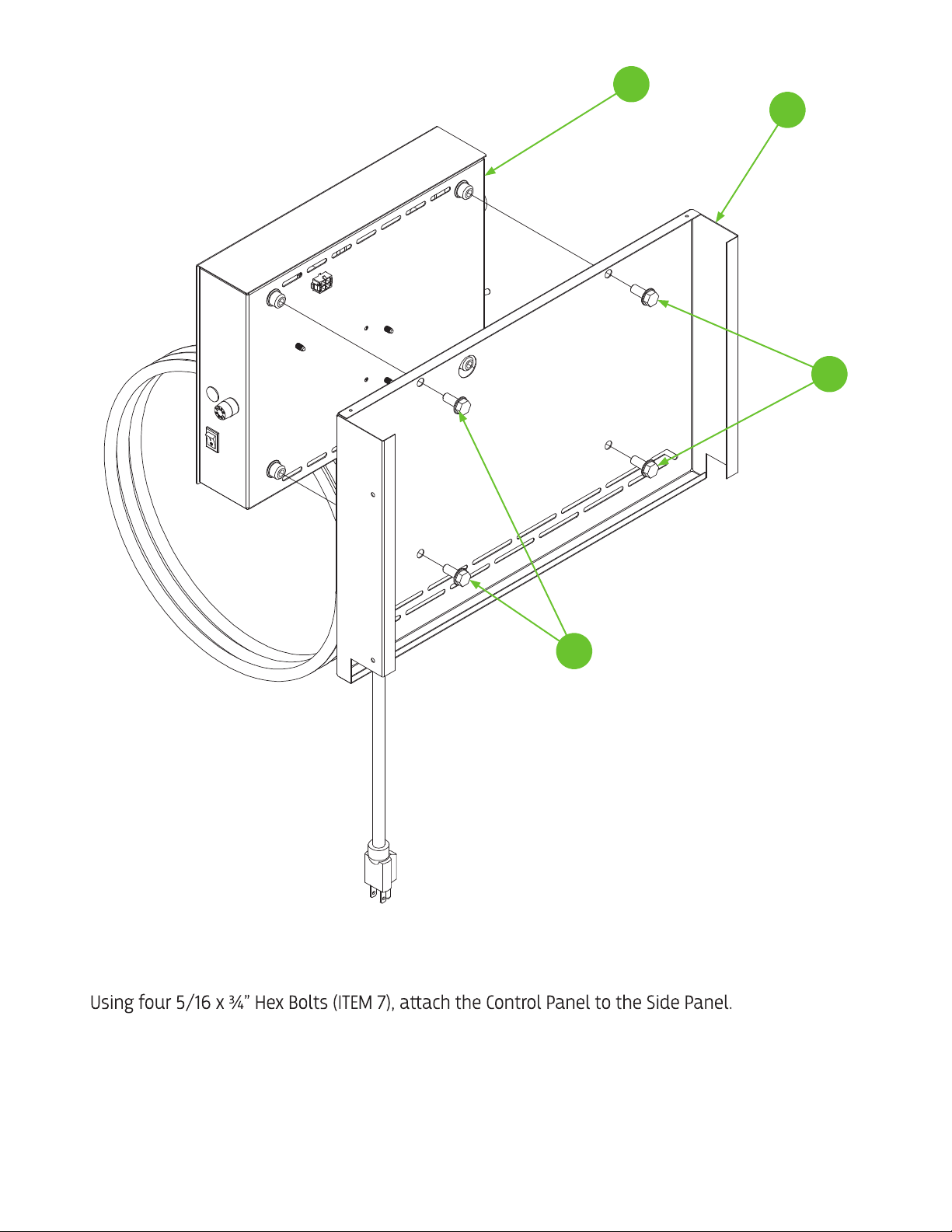
35. Locate the Outer Side Panel (ITEM 20) in BOX 2. This part is without a label.
36. Locate the Control Panel Assy (ITEM 21) from BOX 3.
37.
STEP 6
7
7
20
21

12
38. Install the Control Panel/Side Panel assembled from the previous page to the inner Chamber
assembly by sliding it over Inner Side Panel (ITEM 18) from above, the Gearmotor side.
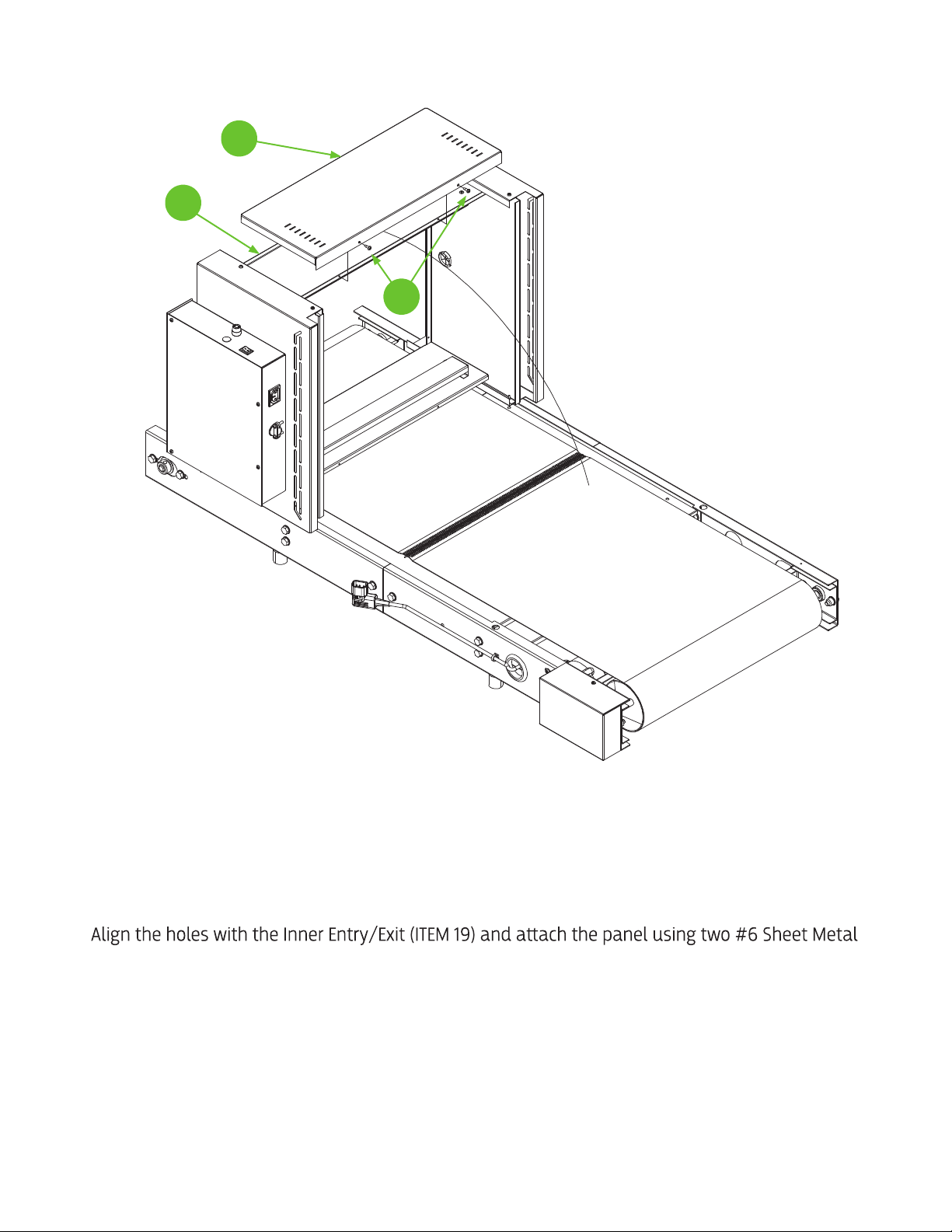
39. Locate the other labeled Outer Side Panel (ITEM 22) from BOX 2.
40. Slide Panel over other Inner Side Panel.
41.
STEP 7
14
22
14
20
14
21 14
13
42. Locate the two Chamber End Caps (ITEM 23) from BOX 2.
43. Rotate the partially assembled chamber onto its end as shown in the figure.
44. Insert one of the End Caps between the two Side Panels with the longest flange to the underside of
the chamber.
45.
Screws (ITEM 14).
46. Repeat this assembly procedure with on remaining End Cap on the reverse side of the chamber.
STEP 8
23
19
14
14
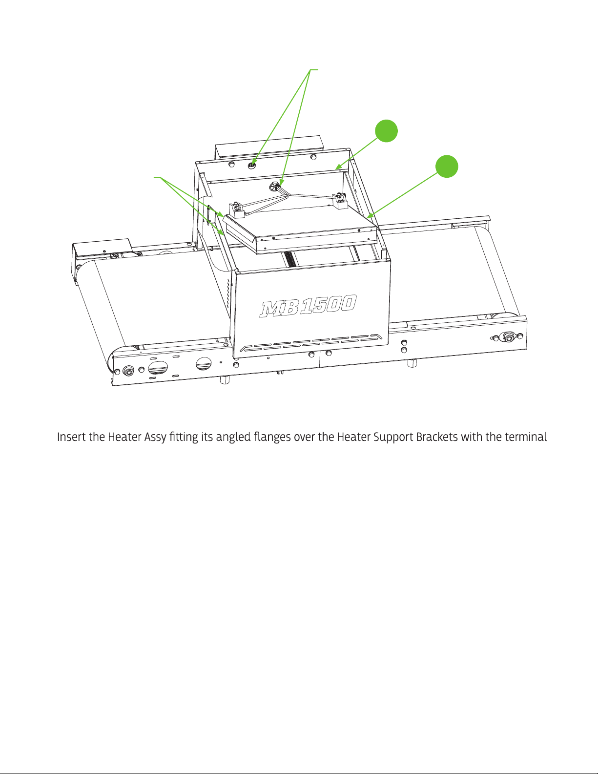
47. Locate the Heater Assy (ITEM 24) from BOX 3.
48.
blocks on the Control Panel side of the Chamber.
49. The fit may be tight. Insert with the leading end of Heater Assy.
50. Insert the plug connector of the Heater Assy through the grommet in the Inner Side Panel (ITEM 18).
51. Connect the plug to the receptacle connector of the Control Panel.
STEP 9
24
18
Insert plug through the grommet andplug
into the connector onthe control panel
Heater anges t over heater
support brackets
15
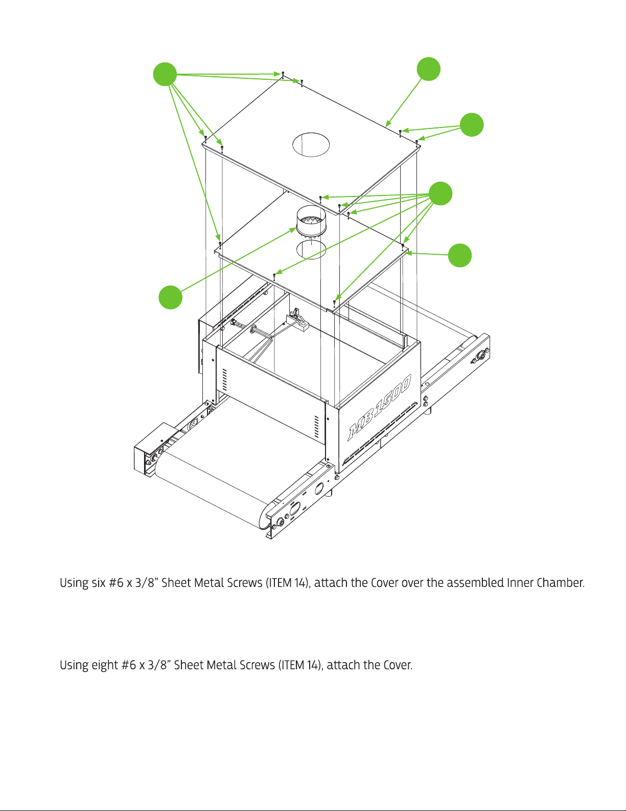
52. Locate the Inner Chamber Cover (ITEM 25) from BOX 2.
53.
54. Locate the 4” Duct Start Collar (ITEM 26) from BOX 2.
55. Insert the tabs of the Start collar into the hole in the Inner Chamber Cover and bend up to secure.
56. Locate the Chamber Cover (ITEM 27) from BOX 2.
57.
STEP 10
Insert the collar into
hole bend tabs to secure 26
14
14
25
14
27

16
58. Locate the two Chamber Curtains (ITEM 28). Mount them on the Entry and Exit of the Heating
Chamber at the desired height.
28
28
STEP 11

17FIGURE 13
TRAVEL DIRECTION
Conveyor Power Switch
CONVEYOR SPEED CONTROL
HEATER POWER INDICATOR LIGHT
HEATER CHAMBER POWER SWITCH
Conveyor Fuse
TRAVEL DIRECTION
CONTROLS OVERVIEW

18
RECOMMENDED INITIAL START-UP PROCEDURE:
1. Plug the Control Panel into a suitable power source.
2. Turn Belt Speed to 5. Flip the rocker switch for Conveyor Speed to the ON position to start the conveyor
.
Listen for any unusual noises. Check to see if the rubber edge guide is riding in the roller drum
grooves.
3. Turn the Heater Chamber Power Switch to the ON position. The green indicator light will illuminate.
Note:
/// caution ///
DO NOT operate Heating Chamber unless the belt is moving. Heat will damage an idle belt.
4.
both the entrance and exit ends of the chamber. The area should be warm.
/// caution ///
The heating element is exposed inside the chamber and is operating at
very high temperatures. Keep your hand close to the moving belt (without touching it).
Note: Some smoke/vapor and odor may be noticed during initial start-up due to residual material
5.
Conveyor speed can be determined by placing a small item, like a coin, on the conveyor belt and
recording the time it takes to travel through the chamber. (For curing plastisol inks on t-shirts, 30
seconds through the Heater Chamber is a good initial speed to begin your evaluation.)
Note: The speed and temperature of the unit may vary slightly with fluctuations in power/voltage
servicing the equipment.
the equipment is being used for curing ink on garments, it is recommended to wash the processed garment
as the definitive test.
The conveyor dryer is now ready for normal use and operation.

19
CONTROL PANEL MAINTENANCE:
1. TurnOFF the power to both the Heater Chamber and Conveyor. Unplug the dryer from its power
source.
2.
control panel are secure by checking the “tightness” of each termination screw (or wire nut as may be
applicable) and then “tugging” on each conductor.
1. The belt should be replaced if it has any tears, voids, separations, fraying, or no longer rides in the
roller drum groove due to excessive wear.
2. Belt tension: the belt will relax over time and tension may have to be adjusted by the instructions
above.
MANUFACTURER’S WARRANTY
All products are warranted against defects in workmanship at the time of shipment.
manufactured by the dryer’s manufacturer without charge F.O.B. factory that may prove defective within 12
months from the date of shipment, which is returned to BBC Industries, Inc.
The above warranties are the only warranties made with respect to the equipment. There is no implied
EXCLUSIONS:
• Transport by carrier
• Corrosion
• Operation or use in a manner inconsistent with specifications and/or operating instructions
• Ordinary wear, accident, improper installation, or maintenance
• Alterations made to equipment in any way
The manufacturer shall not be liable for any losses or damages, including but not limited to incidental or
installation or during its operation or use.
Shipment of defective parts to the manufacturer and the return shipment of any repaired or replacement
parts from the manufacturer shall be at the purchaser’s/user’s expense.
Table of contents
Popular Dryer manuals by other brands


Beko
Beko DRY 733 CI user manual

Alliance Laundry Systems
Alliance Laundry Systems IGHP190E Programming manual

Bosch
Bosch WTX87MF0CH Installation and operating instructions

American Dryer Corp.
American Dryer Corp. AD-75 parts manual

GE
GE DSKS333E Dimensions and installation information

STATESMAN
STATESMAN TVM07W instruction manual

Electrolux
Electrolux EDE 57160W user manual

AEG
AEG LAVATHERM 57760 electronic operating instructions

Frigidaire
Frigidaire Affinity FAQE7072L Specifications

Bosch
Bosch WTL 6101 Instruction manual and installation instructions

Beko
Beko B3T48241DW user manual

Airstream
Airstream 1000 Series Quick reference guide