BC lift BCSA User manual

INSTALLATION MANUAL
BC PLATFORM LIFT type BCSA
BC lift a/s
H.C. Oerstedsvej 13 -DK-9900 Frederikshavn
Telefon +45 98 43 54 44 -Fax +45 98 43 54 45 –E-mail: bclift@mail.tele.dk

BC lift a/s
1
Contents.
Text Section
Introduction……..…………………….………………. 2
Tecnical details………………………………..……….. 3
Site requirements before lift installation………….…. 4
Arriving on installation site ………………………….. 5
Check all lift parts before installation start…..……... 6
Installation……………………………………………… 7
Test…………………………………………………….. 25
Cleaning lift and site. Initial lubrication…………….. 32
User instruction……………………………………….. 33
Notes…………………………………….……………… 34

BC lift a/s
2
Introduction
Congratulation, you are about to install a BC Platformlift.
Why use this installation manual?
The BC Platform lift is an advanced staircase platform lift, specially
developed for transporting a person with or without a wheelchair.
The description in this installation manual applies only to the BC Platform
lift, and contains all the information you will need to make a correct and
succesfull installation.
If you have any questions or commends to this manual or the equipment,
please do not hesitate to contact BC Lift a/s
We whish you good luck.
BC lift a/s
H.C. Oerstedsvej 13
9900 Frederikshavn Before….
Tlf.: +45 98 43 54 44
Fax.: +45 98 43 54 45
E-mail: bclift@mail.tele.dk
http:\\www.bclift.dk
After.

BC lift a/s
3
TECHNICAL DETAILS.
General
Power supply voltage 3x380 VAC/1x220VAC Rate of movement 12 cm/s
Frequency 50 Hz Max. load on platform 225 kg
Current consumption 2.4 Amp Relative humidity 10%-90%
Power consumption 0.55 kW IP value 66
Fuses 8 Amp

BC lift a/s
4
SITE REQUIREMENTS BEFORE LIFT INSTALLATION.
•Access to power supply close to the lift installation in the top operation panel.
•The power supply must comply according to technical details.
•The output from the power supply must be equipped with a main circuit breaker,
according to local authority and safety regulations.
•The site must be clean and free from any obstacles.
•Access to power for hand tools.
Power supply. Main
circuit breaker as close
to the lift installation as
possible.
Top operation panel
(empty shown)

BC lift a/s
5
ARRIVING ON INSTALLATION SITE.
•Introduce yourself to the client.
•Hand over the user manual to the client. The client can
then become familiar with the content of the manual, before
user instruction will take place.
•Check that the staircase is the same as that shown on the
installation drawing.
•Check that site requirements before installation has been fulfilled.
•Bring in all the lift parts.
•Bring in all tools needed.

BC lift a/s
6
CHECK ALL LIFT ITEMS BEFORE INSTALLATION START.
In order to reduce installation time and avoid unneccesary waste time,
following lift items must be present before installation start.
•Main rail.
•Main rail end covers.
•Supporting rail.
•Lift body.
•Lift body shell.
•Lift platform.
•Top operating panel.
•Bottom operating panel.
•Platform kit.
•Bolts with expansion plugs,
for either wall-or foot mounted rails.
•Electrical cables
•Safety bars
•Support wheels
•Emergency handle.

BC lift a/s
7
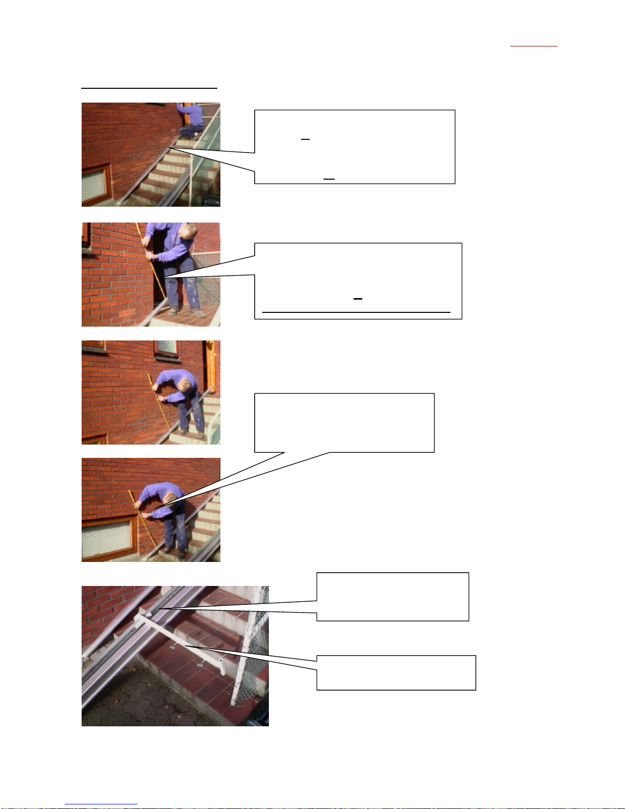
INSTALLATION.
Before installation can be initiated, the following basic measurements and conditions must be
observed.
According to enclosed drawing, it is important to locate the straight line X, starting from the top of the
staircase, called the top nose, down on top of the highest step and finally ending in point Xon the
floor.
We already have the slope of the staircase, determined at order time.
Using enclosed table, we can now find the two measurements aand b.
Measure ais the angular distance from line Xto the upper side of the main rail.
Measure bis the angular distance between the lower side of the main rail and the upper side of the
supporting rail.
BC lift a/s
8
Installing the main rail.
When measuring from the upper side
of the supporting rail, remember to
suptract the thicknes of the supporting
rail from measure a.
Always take an angular measurement.
Use the supporting rail to establish
the line X. Make sure the rail is hold
tight on the top nose. The hi
ghest step
further down will then determine the
slope of line
X.
Always take min. 3 angular
measurements down the line to
position the main rail as accurate
as possible.
Remove cover on main rail,
to get access to the tooth
bar.
Mount ajustable supports for
lining up. (not standard).

BC lift a/s
9
Main rail with two supports.
Main rail is adjusted on the
two supports so the marking
on the wall, fits along with
the upper side of the main
rail.
The end of the main rail
should be vertical above the
top nose of the staircase.
Supporting rail.
Check for free space.
Make sure that nothing
exeeds the main rail

BC lift a/s
10
The main rail is now installed.
Drill all the holes.
Diameter: 12 mm.
Depth: min. 100 mm.
Insert: Plugs U12
and tight with screw:
M10 x 90.
In this situation,
a special designed
rail support is needed
for the lower end of
the main rail.
Support used: Type V

BC lift a/s
11
Installing the supporting rail.
Installation of Main -and Supporting rails are completed.
The angular distance bfrom
under side of main rail to upper
side of supporting rail, is
marked.
The supporting rail should
reach the ground/floor.
Drill all the holes.
Diameter: 8 mm.
Depth: min. 100 mm.
Insert: Plugs U8
and tight with screw:
M6 x 100.
Rail installation completed.

BC lift a/s
12
Installing operating panels and cable ducting.
Installation of operating panels and cable ducting are completed.
Installation of operating
panel, downstairs.
Installation of operating
panel, upstairs.
Cable ducting.

BC lift a/s
13
Installing lift body.
Remove the upper
end-stop.
Back side of the lift body.
Remember to loosen the cable,
before inserting the wheels in
the track of the main rail.
Insert from upper end.
Lift is inserted from the upper
end.
Lift is now hanging freely.

BC lift a/s
14
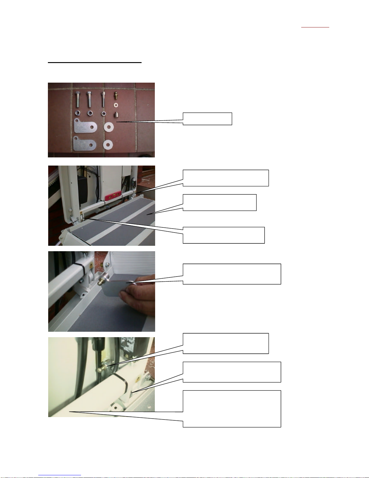
Installing support wheels on the lift body.
Drill a hole that points direct to
the midle of the supporting rail.
See next picture.
Liftbody is now hanging
vertical, and this hole must
point directly to middle of the
support rail.
Use a spirit level, for the
horizontal alignment .
Tight this bolt in each side.

BC lift a/s
15
Installation of lift body is now completed.
The hole must be within the
penetration on the backplate,
and modified into a square of
approx. the shown size.
Support wheels installed.
Do not tight the bolts
yet.
Use a spirit level, for the
vertical alignment.
Use nuts and counter nuts to
set the vertical alignmentn
and tight all well.

BC lift a/s
16
Installation of electrical cables.
Cable from lift body is
inserted in the free end of the
flexible cable ducting .
The free end of the flexible
ducting, is pulled up to the
back side of the lift body.
The free end of the flexible
ducting, is locked/clipsed on
the back side of the lift
body.
Cable from the lift, comming
from the flexible ducting, to
the upper control panel.
Cable to the lower control
panel, comming from the
upper control panel, is
inserted in track in the
aluminium rail, i.e. main
rail.

BC lift a/s
17
Installation of electrical cables are now completed.
Lower Control panel.
The terminals are numbered
according to the wires in the
cable, i.e. 1-2-3-5-6-7-8-9-10-
11.
NOTE!! Wire number 4 and
Earth are not used in the
terminal.
Upper control panel.
Terminals to the LOWER
control panel, are numbered
according to the wires in the
cable, i.e. 1-2-3-5-6-7-8-9-10-
11.
NOTE!! Wire number 4 and
Earth are not used in the
terminal.
Upper control panel.
Terminals to LIFT, are
numbered according to the
wires in the cable, i.e. 1
-2-3-4-
5-6-7-8-9-10-11 and Earth.
Upper control panel.
Terminals to SUPPLY.
Connect 3 phases + E+N
according to terminal marks.
BC lift a/s
18
Installation of lift platform.
Pla
tform kit.
Platform on lift body.
Bolt temporary inserted.
Bolt temporary inserted.
Assembly of arm for platform
turning damper.
Arm mounted between the lift
console and lift body flanges.
Arm for platform turning
damper.
In the other side:
Arm for platform actuator
mounted between the lift
console and lift body flanges.

BC lift a/s
19
Installation of Bowden cables to ramps.
Nylon shim inserted.
Arm in position.
Remove the rubber
gaskets from bowden
cable ends, and push
cable totally into the
fixpoint and lock it
with the centre screw.
Centre of screw must
hit this groove.
Bowden cable fixpoint
with center screw.
Bowden cable fixpoint.
Rubber gaskets re-
mounted.
Loosen the bowden
cable upper fixpoint
with an Allen key.
Turn the c
able around,
so it lays flat to the lift
body. Tigh again.
See next picture.
Other manuals for BCSA
1
Table of contents
Other BC lift Stairlift manuals


