vimec V65 B.I. User manual

30 - 10 - 2014
Vimec s.r.l
Via Parri, 7 - 42045 Luzzara - Reggio Emilia- Italy
Tel. + 39 0522 970 666 - Fax. + 39 0522 970919
www.vimec.biz
STAIRLIFT
V 65 ELECTRONIC
MODEL
B.I. - INDEPENDENT BARS
B.R. - RETRACTABLE BARS
USE AND MAINTENANCE Page 03 - 17
ASSEMBLY INSTRUCTIONS Page 18 - 42
SPARE PARTS MANUAL Page 43 - 87
MANUAL CODE
VIMEC reserves the right to make any modication and change to its products at any time in compliance with the technical developments.
7512132
DATE __________ APPROVED ____________
Original instructions
7512132

31/01/2010
VIMEC S.r.l. “Original” Declaration of Conformity
_________________________________________________________
“EC” DECLARATION OF CONFORMITY
The manufacturer:
Via Parri n.7 , 42045 Luzzara (R.E.) ITALIA
Tel. 0522/970666 r.a. Fax 0522/970919
(Name and address of the person authorised to compile the technical le:
Name: Marco Marchetti
Address: Via Parri n.7, 42045 Luzzara (R.E.) ITALY - Tel. +39/0522/970666)
states on his own responsibility that the stair lift for users on a wheelchair type:
V65 – B.I. – B.R. – Serial Number:
complies with the following Directives:
- Directive 2004/108/EEC “Electromagnetic Compatibility”
- Directive 2006/95/EEC “Low Voltage”
- Directive 2006/42/EEC “Machinery Directive”
The Legal Representative
Ing. Giuseppe Lupo
Luzzara, lì

3
TO ENSURE SAFE OPERATION
WARNING
This symbol indicates important instructions for safety.
Compliance with these instructions does not release users from their obligation to follow all additional
safety regulations.
Read this manual carefully before assembling, starting up, using or maintaining the stairlift.
The best way of preventing accidents is care and attention when using the stairlift.
Comply with the information supplied by the data-plates of all kinds applied to the stairlift.
Replace any damaged data-plates immediately.
All procedures on the stairlift except for normal use must be carried out by professionals.
Comply with the skill level indicated for the various operations, with reference to the following symbols:
O Trained operator
OC Trained operator with specic skills
OS Skilled operator committed by the manufacturer
The stairlift must always be operated by an ADULT well informed about all the operating functions and
the precautions envisaged by this manual.
CONTENTS OF THE MANUAL
1. Stairlift and manufacturer identication data Page 04
2. After-sales service Page 04
3. Description of the stairlift Page 05
4. Technical specications Page 08
5. Intended and improper uses of the stairlift Page 09
6. Preparation for commissioning Page 09
7. Correct use of the stairlif
in independent bar and retractable bar version Page 10
8. Safety systems Page 13
9. Maintenance Page 15
10. Wiring diagrams Page 17
11. Vibrations - Airborne noise levels Page 17
12. Information on disposal of substances and parts of the stairlift Page 17
USE AND MAINTENANCE

4
I - 42045 Luzzara (RE)
Via Parri,7 - Tel. + 039 0522 970 666
DEALER STAMP AND REFERENCE FOR AUTHORISED AFTER-SALES SERVICE
2) AFTER-SALES SERVICE
1) STAIRLIFT AND MANUFACTURER IDENTIFICATION DATA
SERIAL Nr.
_ _ _ _
SERIAL Nr.
_ _ _ _
WORKING LOAD
- - - kg
TYPE V65
SERIAL Nr. (Nr) - - - -
YEAR OF MANUFACTURE - - - -
WORKING LOAD (Kg) - - -
POWER (V / A / Hz) 230 / 5 / 50

5
a
c
b
d
c
f
e
a
b
b
d
e
g
h
3) DESCRIPTION OF THE STAIRLIFT
3.1) Description
Lift unit - Fig. 1
Comprises:
- carriage
- load-bearing structure
- safety bars - Fig. 1/a.
- load platform - Fig. 1/c.
- casing - Fig. 1/b.
- control board - Fig. 1/d.
Contains:
The control board carries the following controls:
- control enabling key with start button - Fig. 2/a.
- up/down buttons - Fig. 2/b.
- overload indicator light - Fig. 2/c (standard operated
only for 1250x800 and 1050x900 platforms).
- bell push-button - Fig. 2/d.
- emergency stop (red mushroom-head button) - Fig.
2/e.
- radio and stairlift tension indicator light - Fig. 2/g.
- floor selector button - Fig. 2/h
On the lift unit:
- connection for handwheel for manual operation -
Fig.2/f.
- motor - Fig. 3/a.
FIG.2
FIG.1
START

6
a
c
b
b
c
b
a
d
b
b
a
c
b
b
b
c
de
b
a
- transmission components - Fig. 3/b (units with gradient
< 20°).
- electric system - Fig. 3/c.
As an optional, the stairlift can be also provided
complete with double drive chain (Fig. 3 bis) and chain
microswitch (Fig. 3 bis).
Rails - Fig. 4
Comprises:
- Rail - Fig. 4/a.
- Wall connections - Fig. 4/b.
- Charging station or busbar - Fig. 4/c.
- Feet for stairs (optional) - Fig. 4/d.
3.2) Main safety measures against risks of a me-
chanical nature
- Safety bars - Fig. 5/a.
- Retailer guard boards - Fig. 5/b.
- Anti-impact and anti-shearing sensor edges on stairlift
body - Fig. 5/c.
- Anti-impact and anti-shearing sensor edges on plat-
form - Fig. 5/d.
- Anti-crushing sensor base in platform - Fig. 5/e.
- Gradual action mechanical safety gear - Fig. 6/a.
FIG.5
FIG.3
FIG.4
FIG.3 bis

7
a
a
b
c
d
e
f
3.3) Main safety measures against risks of an elec-
trical nature
Protection against overcurrents, overloads, acci-
dental contacts and direct and indirect contacts.
- Differential circuit breaker on power supply system.
3.4) Warning and compulsory procedure signs and
data-plates
The stairlift is tted with the following warning and
compulsory procedure signs and data-plates:
- Emergency switch must be pressed before operation
in manual mode - Fig. 2/e.
- Stairlift identication plate.
- Sign for manual release of bars and platform
3.5) Supply condition
- Rails and rail connections - Fig. 7/a.
- Frame with carriages - Fig. 6.
- Set of bars - Fig. 7/f.
- Platform - Fig. 7/c.
- Casing - Fig. 7/d.
- Handwheel for manual operation - Fig. 7/e.
The system must be installed by skilled ope-
rators authorised by VIMEC.
FIG.6
FIG.6 bis
FIG.7

8
3.6) Reference technical standards
The stairlift complies with the following norms:
- Directive 2004/108/EEC “Electromagnetic Compatibility”
- Directive 2006/95/EEC “Low Voltage”
- Directive 2006/42/EEC “Machinery Directive”
4) TECHNICAL SPECIFICATIONS
- Drive system
Worm gear reduction unit Ratio 1/40
- Performance levels
Travel direction Forward/backward
Speed (up/down) 0.15 m/s
Capacity 1 person
Gradient from 0° to 50°
Working load 250 kg up to 45°
- 300 kg for platform with P ≤ 770 and gradient up to 45°
- 250 kg for platform with P > 770 and gradient up to 45°
- 200 kg with gradient between 45° and 50°
- Duty cycles
Normal service 20 min/hour max.
- Ambient conditions for outdoor stairlifts
Temperature From -10°C to +60°C (suggested and recommen-
ded)
Humidity maximum 70% (use in bathrooms and swimming-pools is
not permitted) (suggested and recommended)
- Electrical system
Drive motor 24 V d.c. 1 kW
Power absorption 40 A
- Controls
Up/down control button “Dead man” type
Emergency stop button with detent
Key-switch

9
5) INTENDED AND IMPROPER USES OF THE STAIRLIFT
5.1) Intended uses
The stairlift is a system for transporting one person SEATED ON A WHEELCHAIR OR ON A SPECIAL
SEAT (optional), suitable for installation on staircases having the following characteristics:
- Location: Indoor and outdoor
- Steps: Parallel
- Gradient: Minimum 0° - Maximum 50°
Intended user: The intended user is self-sufcient and physically and mentally capable, familiar with
the stairlift’s operations and the use and maintenance instructions.
WARNING: If the person using the system is not self-sufcient, the stairlift must be operated by
another person acting as attendant. While the stairlift is in motion, sit still and do not move or rock.
5.2) Improper uses
- Transporting objects on the platform
- Overloading the stairlift (e.g., disabled person with electric wheelchair having total weight in excess
of the maximum permitted working load. See section 4, Technical Specications).
- Use of the stairlift by unauthorised persons (e.g. children, people who do not meet the requirements
specied in point 5.1)
Improper uses Problems
Use on stairs having gradient
greater than 50°: Overheating of motor
User standing on platform: Risk of falling
Operation by unsuitable operator: Risk of falling
Transporting more than one person: Risk of falling and of overheating of motor
6.1) Preliminary checks
Checks to be made before the stairlift is put into service.
Skill level: OS - Skilled operator committed by the manufacturer.
ITEM CHECKED RESULT OF CHECK
Controls: Correct operation in response to controls.
Efciency of emergency stop.
Safety devices: Check that the safety device is tripped, stopping the stairlift.
- Sensor edges
- Electric limit switches
- Over-run safety device
- Anti-crushing platform base
Power supply: 230 V - 5A - 50/60 Hz.
Earth connection: Check that the stairlift system’s earth line is connected to the
earth line of the mains system.
6) PREPARATION FOR COMMISSIONING
AWARNING: DO NOT MAKE MODIFICATIONS INTENDED FOR ANY USE, DO NOT INSERT
EXTRANEOUS OBJECTS OR LIQUIDS IN HOLES OR CRACKS, DO NOT SPRAY LIQUIDS ONTO THE
STAIRLIFT

10
b
a
a
c
g
c
e
b
d
i
h
ih
m
l
FIG.10
FIG.9
FIG.8
7) CORRECT USE OF THE STAIRLIFT IN INDEPEN-
DENT BAR AND RETRACTABLE BAR VERSIONS
WARNING: BEFORE USING THE STAIRLIFT,
READ THIS MANUAL CAREFULLY. The stairlift must
only be used in accordance with the intended uses
described in section 5.
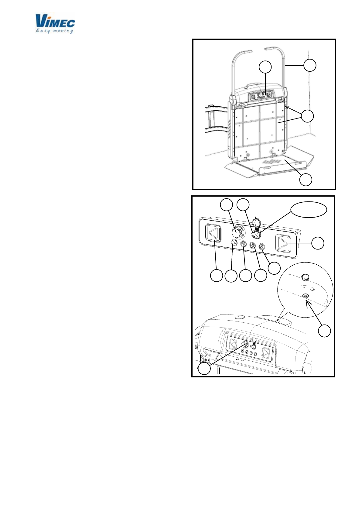
7.1) Starting position
The stairlift is parked at one end of the staircase with
the platform folded up (Fig. 8/a) and the bars in rest
position (Fig. 8/b) with the master key turned to ON.
The stairlift is powered up.
7.2) Using the stairlift
WARNING: Always keep access to the plat-
form and the master switch unrestricted.
NEVER overload the stairlift.
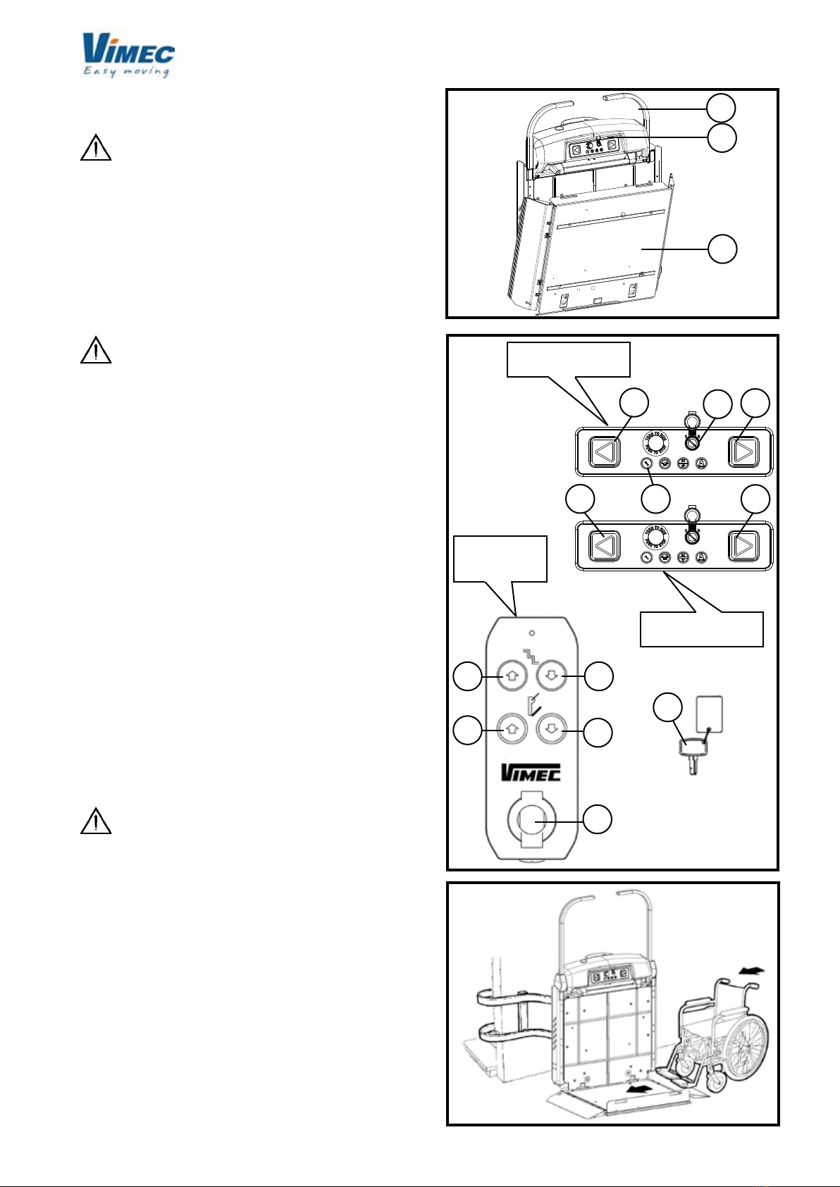
1) For stairlifts with manual platform (standard).
- Bring the down side bar into the working position by
pressing the button (Fig. 9/d) on the control board at
the oor.
- Lower the platform by hand.
- If the stairlift is at the lower oor, bring the down side
bar into the rest position to allow the wheelchair to
move onto the platform.
1)
For stairlifts with motor-operated platform (optional)
- Insert the key and turn it to position (1) ON using the control
board at the oor.
- Open the platform by pressing the button provided (Fig. 9/e).
The side guard moves to the drive-on position and the down
side bar to the working position.
If the stairlift is at the lower oor, return the down side bar
to the rest position to allow the wheelchair to move onto the
platform.
2) Get onto the platform, facing in the travel direction
and in a central position (Fig. 10) to allow the guard
to move into its sensor position. Lock the wheelchair
brakes. If the wheelchair is electric, turn it off.
WARNING: The wheelchair must be positio-
ned on the platform so that no part of the body or
the wheelchair projects from the platform. When
the stairlift is in motion sit still without moving or
rocking.
3)
Insert the key (Fig. 9/m) and turn it to position (1) ON, then
turn to S and release.
4) Press the up button (Fig. 9/i); the guards and bars
automatically move to the safety position and the stai-
rlift sets off.
In stairlifts with an intermediate stop, press the button
(Fig. 9/l) once to select the rst stop, press twice for
the second stop, three times for the third stop, and so
on. Then keep the up/down button pressed until the
landing oor is reached.
The yellow light of the button (Fig. 9/l) ashes upon
selection and until arrival to the selected oor, then the
light is on without ashing.
In case the oor selection is wrong, keep the button
pressed for 3 seconds to reset, then select again
RH CONTROL
BOARD ON LIFT
LH CONTROL
BOARD ON LIFT
FLOOR
CONTROLS

11
a
c
b
a
bd
a
FIG.11
FIG.12
5) The stairlift stops at the destination oor; release the
up button and press it again, the bars and the guard
facing in the up direction automatically move to the
drive-off position. The guard and the bar facing in the
down direction are now locked in the safety position, to
ensure safety during drive-off and upon new drive-on.
6) When the down button (Fig. 9/h) is pressed, the bars
and guard facing in the up direction move to the safety
position and the stairlift sets off.
7) The stairlift stops at the destination oor; if the down
button (Fig. 9/h) is kept pressed, the bars and the
guards automatically move to the drive-off position.
8) Return the stairlift to its initial condition (with platform
folded up and bars in rest position) (Fig. 8), turn the
key off and remove it.
N.B: The bars and guards are mechanically locked
in position as long as the stairlift is travelling between
the oors.
WARNING: The passenger must always
remain in the recommended position, with the
wheelchair brakes on, if the wheelchair is electric,
turn it off, as long as the stairlift is in motion. The
feet must be kept on the wheelchair foot-rest and
the free hand on the platform handle (Fig. 11/c).
WARNING: The passenger must always
look in the travel direction and must stop the stai-
rlift immediately if there is anyone on the travel
route.
WARNING: During operation of the stairlift
the landings and travel route must always be illu-
minated (minimum 50 Lux measured at oor level).
WARNING: Use of the stairlift by unau-
thorised persons is not permitted. The key which
enables use of the stairlift must always be kept in
a safe place and must only be accessible to autho-
rised persons. The key must always be removed
at the end of each trip. Leaving the key always in
place is not permitted.
WARNING: Never leave the platform halfway
up the staircase.
WARNING: Never use the stairlift unless a
trained person is available to operate it in manual
mode in an emergency.
WARNING: Never place your hands or any
objects close to the rails or platform while the stai-
rlift is in motion.
WARNING: If the machine is installed out-
side, always cover it with its protection cloth after
using it. Remove the keys from the control panels
and close the rubber lid (Fig. 9/g).
Note for motor-operated platform
This device tips up the platform by means of an electro-
mechanical actuator.
The platform may be opened and closed by pressing the
buttons provided on the control board at the oor (Fig.
9/b) and (Fig. 9/e). A special manual device makes it
possible to close the platform in case of emergency:
1) Push the release button (Fig. 12/a) paying attention
to make a light pressure on the platform to avoid a
sudden shutting.
2) Pull the platform gently, until the complete shutting.
3) Reset the normal functions of the stairlift after the
emergency by a manual complete opening of the
platform.
WARNING: The platform can only be operated
with the down side bar in the working position.
N.B: If the platform folding-up button is accidentally
pressed when someone is on the stairlift, a motor
overcurrent device is tripped and cuts out the electro-
mechanical actuator. The device resets automatically
when the button is released.

12
BAR
OPENING BUTTON
FIG.15
7.3) Stairlift operated by attendant.
If the person using the stairlift is not self-sufcient, it
must be operated by an attendant, using the remote
control board (Fig. 13) or the control board with spiral
cable (Fig. 14), depending on the customer’s request.
The attendant must follow the stairlift from behind with
respect to the moving direction.
Note
Push the oor selection button (push only once for the
rst intermediate oor; twice for the second intermediate
oor) (Fig. 14).
7.4) Stairlift stopped at the other end of the staircase
(optional call - send function).
1) Insert the key in the control board at the oor and
turn it to ON.
2) Keep the call or send button (Fig. 9/c) and (Fig. 9/d)
pressed until the stairlift has reached its destination.
3) Remove the key from the control board, close the
rubber lid (Fig. 9/g).
WARNING: The call/send function only works
with the platform fully folded-up.
WARNING: Never send/call the stairlift to/from
a oor unless the WHOLE travel route can be seen.
7.5) Stairlift with seat for transporting a seated
passenger (optional)
WARNING: the seat max. working load is 115
kg. While the stairlift is in motion, the passenger must
always remain in the position shown in Fig. 15 and
must always keep their free hand on one of the bars.
After use, raise the folding seat and set the stairlift as
described in 7.2-8 (Fig. 8).
7.6) Emergency manual operation
Skill level OC: Trained operator with specic skills
This emergency operating mode is used to bring the
passenger to a oor in case of a power black-out or
system failure.
WARNING: before operating in manual mode,
the operator MUST press the emergency switch and
remove the key (Fig. 9/m).
Proceed as follows:
Moving the stairlift
1) Remove the central cap from the casing (Fig. 16/a).
2) Fit the handwheel provided (Fig. 16/b) into the hole,
tting it into the square shaft (Fig. 16/c) and turn the
handwheel to move the stairlift.
3) After reaching the oor, remove the handwheel and
close the cap again.
4) Restore normal operation of the stairlift once the
emergency conditions cease.
FIG.13
UP/DOWN
BUTTONS
DISABLED
BUTTONS
FLOOR
SELECTOR
PLATFORM
OPENING / CLOSING
BUTTONS
UP/DOWN
BUTTONS

13
a
b
c
b
aa
b
a
a
FIG.18
5) Bring the stairlift to the “home” oor (reset) to reset
its programming.
Releasing the safety bars in an emergency
1) Press the emergency STOP button.
2) B.I. (Independent bars),unscrew the two bar rele-
ase screws on the front of the stairlift body above the
handle (Fig. 17/a).
2) B.R. (Retractable bars), screws at the bottom on
the front have to be undone (one for each safety bar
- Fig. 18/a).
3) Raise the bars by hand (Fig. 17/b-18/b) and hold
them in position while the passenger gets off the
stairlift.
4) Screw the release screws down again, holding
the bar in the working (lowered) position (Fig. 17/b).
5) Check that the bars are xed.
6) Reset the emergency STOP button.
WARNING: During the emergency operation
do not forget that the safety bars are not xed in
the opening position.
WARNING: Operations 4 to 6 must be carried
out by a skilled technician authorised by VIMEC.
WARNING: In case of a system failure or
tripping of the safety gear, call in an authorised
VIMEC technician.
In case of any kind of malfunction, put the stairlift
out of use by turning the key (Fig. 9/m) to OFF.
8) SAFETY SYSTEMS
8.1) Safety devices to prevent impacts and shearing
along the travel rails.
When in motion, the platform and the body of the stairlift
are protected by sensor edges which stop the stairlift if
it touches an obstacle of any kind - Fig. 5.
However, they do allow the stairlift to be moved in the
opposite direction to that in which the obstacle was
encountered, to allow removal of the obstruction.
8.2) Safety devices for the user.
a) Safety gear - Fig. 6/a.
The stairlift is equipped with a gradual action mechani-
cal safety gear. It is tripped if the drive components fail,
or if the normal downward travel speed is exceeded by
a pre-set amount.
When tripped, this device stops the stairlift.
ATTENZIONE:
in this case the stairlift remains
locked out of use and an authorised VIMEC techni-
cian must be called in to put it back into service
.
b) Bars and guard boards
During use the platform (Fig. 11/d) is protected by
two bars (Fig. 11/a) about 100 cm above the platform
surface. The platform is also protected by two guard
FIG.17
FIG.16
BARS
RELEASE
EMERGENCY

14
aa
a
FIG.20
FIG.21
c) Handle
In the top of the stairlift body, it can be used as rest
while the stairlift is in motion - Fig. 11/c.
8.3) Other safety devices
a) Electrical and mechanical limit stops
The “home” sensor acts as limit switch at the bottom
oor. The positions of the other oors, including the
upper oor, are programmed through encoder. In case
of a malfunction, an over-run safety stop device stops
the stairlift - Fig. 19/b
WARNING: In this case the stairlift remains
locked out of use and an authorised VIMEC tech-
nician must be called in to put it back into service.
b) Power supply
The power supply is 220 V~ input from the mains and 27
VDC as output on the busbar or at the charging stations.
The battery on the stairlift is at 24 VDC.
All power and auxiliary circuits are supplied at 24 VDC.
c) Controls
All controls are of the “dead man” type (the stairlift stops
if the nger is taken off the button).
All the control stations (on the stairlift and at the oors)
are enabled by a removable key (no-one can use the
stairlift if the key is not inserted).
WARNING: Do not use the stairlift if the con-
trols are no longer operating in the “dead man”
mode.
d) Operation by hand
The stairlift can always be operated by hand to bring
the passenger to a oor in case of a system failure or
power black-out.
e) Irreversible drive
The worm gear and spiral gear wheel ensure that the
stairlift cannot descend under its own weight and allow
smooth stopping.
f) Motor brake
The electric brake tted on the motor ensures quick
stopping and stability.
boards (Fig. 11/b) which have the dual function of facili-
tating access to the stairlift at the oors (open position)
and of retaining the wheelchair while the stairlift is
moving (safety position at 50°, approximately 155 cm
beyond the platform surface).
The bars and guards automatically move to the safety
position before the stairlift leaves the oor.
The guard facing in the downward direction only opens
at the lower oor.
If the bars or guards encounter an obstacle as they
move into position, a surge protector is tripped, pre-
venting operation of the stairlift. Release the button to
restore operation.
FIG.19

15
g) Emergency stop button
The stairlift is tted with a red emergency STOP but-
ton (Fig. 2/e) which stops all stairlift movements when
pressed.
Stairlift operation is restored by turning the same button
clockwise through 45°.
WARNING: Check monthly that the emer-
gency STOP button is working properly. If the STOP
button does not halt stairlift movements, DO NOT
USE the stairlift! Call in an authorised VIMEC tech-
nician immediately.
WARNING: If the stairlift is to be out of use
for a long time or the power supply is disconnected,
turn the key (Fig. 9/m) to OFF so that the batteries
do not discharge.
WARNING: If the stairlift is not used for a
long period of time, connect the power supply to
the mains for at least 12 hours every month to keep
the batteries charged.
9) MAINTENANCE
VIMEC products are built in compliance with the
current Machinery Directive, that emphasizes the
importance of safety both in designing and building
the machines, as well as of proper installation and
maintenance over time.
Therefore the product warranty is subject to an
ordinary and accurate maintenance of all safety de-
vices and guards. The maintenance service shall be
carried out by skilled technicians specially trained
for this task, in charge of performing the operations
described below.
9.1) Precautions for long periods of disuse:
If the stairlift is to be left unused for a long time, switch
on the power supply to charge the batteries at least
every month.
WARNING: In all cases, call in only staff
authorised by VIMEC for servicing and repairs; use
only original spare parts.
WARNING: The recommended maintenance
frequencies must be complied with.
9.2) Parts requiring regular inspection
Skill level: OS - Skilled operator authorised by
VIMEC.
WARNING: Before starting servicing work
on the rail or stairlift, disconnect the electricity by
pulling the power supply plug (Fig. 20/a) and taking
care to disconnect the battery on the stairlift (Fig.
21/a).
Monthly checks:
WARNING: If the stairlift is used for more
than 30 trips per day, check the mechanical drive
components, safety devices and parts subject to
wear and tear.
Six-monthly checks:
a) Safety devices
Check that on contact with an obstacle, the anti-impact
and anti-shearing sensors stop the stairlift and allow it
to be started in the opposite travel direction.
Check that the stairlift stops in the required positions
at the oors.
b) Checking the interlocking of the platform with
independent or retractable bars (manual platform)
Check that as long as the down side bar is in the rest
position the platform remains locked, whether in the
working or the rest position.
c) Electromagnetic brake
The electromagnetic brake on the motor must stop the
stairlift when fully loaded before the over-run device
is tripped. If necessary, replace the whole brake unit.
c) Drive mechanics
Check that the teeth of the drive sprockets and the
nylon wheels on which the stairlift runs are not worn
or damaged. There must be no grooves or attening
on the wheels. Check the chain for wear.
e) Safety gear
Check that the hook device is free to operate without
friction or excessive clearances and that it trips the
safety microswitch correctly.
To check operation of the safety gear, proceed as
follows:
- Move the stairlift 1-2 metres from the oor.
- Disconnect the power supply by turning the master
switch to OFF.
- Remove the protective panel (Fig. 1/b).
- Press the safety gear hook with a plastic/wooden rod.
WARNING: Keep well away from all unpro-
tected moving parts.
- Restore the power supply and press the down button
until the hook engages. The stairlift will stop when the
safety microswitch is pressed by the hook.
- Reset the safety gear by moving the stairlift upward
in manual mode (see point 7.6).

16
f) Stability of the rail
Check all the xing screws of the connections to the
mounts and any expansion plugs present.
g) General checks
Check all moving parts, the guards, labels and signs.
Check the batteries and the warning lights of the power
supply unit.
h) Rail cleaning
Clean the rail thoroughly.
Annual checks:
a) Controls
Check their operation by trying out the stairlift in all
functions from on board and from the control boards at
the oors in the working modes envisaged.
Make sure that the system has not been tampered with
or modied.
b) Floor control panels
Check that these devices are operating correctly.
c) Electrical system
Check that all electrical components, contactors and
microswitches are operating correctly.
Check the continuity of the earth conductors.
Check that the earth conductors are properly connected
to earth.
d) Testing for stairlifts with sections of rail having
gradient of less than 20°
Move the stairlift to the area with gradient of more than
25° and check that the cam drive roller is 0.5÷1.5 mm
from the cam (see Fig. 64 page 41).
Then move the stairlift to the area with gradient of less
than 20°, and place a weight of 250 kg on it with its
centre of gravity 150 mm from the edge (see Fig. 63
page 41).
Check that the stairlift does not tilt by more than 2°.
e) Check the tension of the drive chain and stretch it as
described at point 19 on page 40 if necessary.

17
9.3) Problem - Possible causes - Possible remedies
Skill level: O - Trained operator
10) WIRING DIAGRAMS
The wiring diagrams are in the folder supplied with the
stairlift
11) VIBRATIONS - AIRBORNE NOISE LEVELS
a) Vibrations
The stairlift induces vibrations in the body and limbs of
the passenger having:
- low frequency and very low acceleration;
- short exposure times for the exposed person.
This parameter is therefore not signicant for safety
purposes.
b) Airborne noise: less than 70 dBA.
12) INFORMATION ON DISPOSAL OF SUBSTANCES
AND PARTS OF THE STAIRLIFT
a) Disposing of rubber and plastics
Place in clean containers and consign to disposal cen-
tres authorised as required by the regulations in force.
b) Oil and toxic materials
The stairlift does not contain any oil or toxic materials
for disposal.
c) Disposing of batteries
Consign batteries to authorised disposal centres or
dispose of them in accordance with the relevant re-
gulations in the country where the stairlift is installed.
Problem
The stairlift does not move in
either travel direction.
The stairlift moves downward
more quickly then cuts out.
The stairlift does not move from
either end of the stair.
The stairlift does not move in one
direction.
The stairlift hits the stop buffers.
The stairlift cuts out and the buz-
zer sounds.
After the stairlift is switched on
and the start button is pressed,
the stairlift moves to the home
oor.
Possible causes
Control enabling key.
Emergency STOP pressed.
Differential circuit breaker trip-
ped.
No power supply.
A safety device has been tripped.
Safety gear tripped.
Over-run safety device tripped.
Control enabling key.
The bars or bottom safe edge of
the platform have been excited
10 times in about 30 seconds.
The stairlift has been switched off
when not at the parking station.
Possible remedies
Turn the key to ON.
Turn the button clockwise throu-
gh 45°.
Press the reset button. If it does
not remain in the ON position,
call in an authorised VIMEC
technician.
Check the power supply; see
point 7.6 (operating by hand).
Call in an authorised VIMEC
technician.
Call in an authorised VIMEC
technician.
Call in an authorised VIMEC
technician.
Turn the key to ON.
Check that there are no ob-
stacles activating the safety
devices (Fig. 5/c-d-e).
Call in an authorised VIMEC
technician.
Switch the stairlift off and then
back on with the key. When
instructed to move, the stairlift
automatically returns to the
home oor. The stairlift respon-
ds correctly to all subsequent
controls.
Wait for the stairlift to reach the
home oor.

18
CONTENTS OF THE MANUAL
ASSEMBLY INSTRUCTIONS
1. System supply condition Page 19
2. Installing the lower rail Page 20
3. Installing the upper rail Page 22
4. Assembling the carriage Page 23
5. Positioning the charging station (if applicable) Page 25
6. Connecting the power supply unit Page 27
7. Connecting the installation engineer’s control panel Page 27
8. Fixing the connecting feet Page 29
9. Fitting the bars Page 30
10. Assembling the platform with driven front access Page 31
11. Assembling the platform Page 34
12. Preparing the stairlift for setup Page 36
13. Setting up the stairlift Page 37
14. Checks on installation Page 37
15. Adjusting rail bend rollers Page 38
16. Adjusting guide shoe supports Page 38
17. Fitting the over-run device cams Page 39
18.
Check the position of the over-run device cam and plates
Page 40
19. Stretching the chain Page 40
20. Final testing Page 40
21. Fitting the casings Page 41
22. Fitting the caps and end covers Page 42

19
b
a
b
b
c
a
d
d
c
de
FIG.1
FIG.2
1) SYSTEM SUPPLY CONDITION
The stairlift is supplied subdivided into the following
components:
Lift structure (Fig. 1/a)
Complete with gear motor, drive components with safety
gear and electrical system.
Batteries (Fig.1/e).
Carrier platform (Fig. 1/b)
Complete with guard boards and bottom safe edge
controlled by safety microswitches.
Bar assembly (Fig. 1/c).
Fixed or retractable (optional) protective bars.
WARNING: Remove the bar assemblies (Fig. 1/c)
before tting the carriages onto the rails.
Casings and on-board control panel (Fig. 1/d).
WARNING: Remove the upper and lower casings
(Fig. 1/d) before tting the carriages onto the rails.
Rail assembly (Fig. 2)
Comprising:
- Lower rail complete with power bus bar for special
applications and supporting feet (Fig. 2/a).
- Upper rail (Fig. 2/b).
- Mounting accessories.

20
a
b
C
D
A
a
a
da
b
a
d
c
AB
160
FIG.3
FIG.4
FIG.6
FIG.7
FIG.5
2) INSTALLING THE LOWER RAIL
- Use the assembly markings (Fig. 3/b) to identify the
rst section of rail, with the bend (Fig. 3/a) starting from
the top oor.
N.B.: If there are no bends, nd the rst straight section
(Fig. 4/a) starting from the top.
- Place the bend in the installation point (Fig. 6/c).
- Referring to the dimensions shown in the installation
drawing (example Fig. 5) extract the feet and lock them
lightly in position with just one screw (Fig. 6/a) for each
connection device (Fig. 6/d).
N.B.: First connect up all sections; only x the feet
afterwards.
N.B.: Make sure that the outer edge of the rail is 160
mm (Fig. 6/b) from the banister or dividing wall.
- Set the bend connection xtures perfectly vertical (Fig.
7) and tighten both the xing screws once adjustment
is complete (Fig. 7/a).
Other manuals for V65 B.I.
3
This manual suits for next models
1
Table of contents
Other vimec Stairlift manuals