BCM MX610H User manual

1
MX610H
Intel® 12th Generation Core™Processor Mini-
ITX Motherboard With Intel® H610E Chipset
User’s Manual
Edition 1.0 –Oct, 2022

2
FCC Statement
This device complies with Part 15 of the FCC Rules. Operation is subject to the following two conditions:
1) this device may not cause harmful interference, and
2) this device must accept any interference received, including interference that may cause
undesired operation.
This equipment has been tested and found to comply with the limits for a Class B digital device, pursuant
to Part 15 of the FCC Rules. These limits are designed to provide reasonable protection against harmful
interference in a residential installation. This equipment generates, uses and can radiate radio frequency
energy and, if not installed and used in accordance with the instruction manual, may cause harmful
interference to radio communications. However, there is no guarantee that interference will not occur in a
particular installation. If this equipment does cause harmful interference to radio or television reception,
which can be determined by turning the equipment off and on, the user is encouraged to try to correct the
interference by one or more of the measures listed below:
■Reorient or relocate the receiving antenna.
■Increase the separation between the equipment and receiver.
■Connect the equipment into an outlet on a circuit different from that to
which the receiver is connected.
■Consult the dealer or an experienced radio/television technician for help.
Notice
BCM Advanced Research, ALL RIGHTS RESERVED.
No part of this document may be reproduced, copied, translated, or transmitted in any form or by any means,
electronic or mechanical, for any purpose, without the prior written permission of the original manufacturer.
Trademark Acknowledgement
Brand and product names are trademarks or registered trademarks of their respective owners.

3
Disclaimer
BCM Advanced Research reserves the right to make changes, without notice, to any product, including
circuits and/or software described or contained in this manual in order to improve design and/or performance.
BCM Advanced Research assumes no responsibility or liability for the use of the described product(s),
conveys no license or title under any patent, copyright, or masks work rights to these products, and makes
no representations or warranties that these products are free from patent, copyright, or mask work right
infringement, unless otherwise specified. Applications that are described in this manual are for illustration
purposes only. BCM Advanced Research makes no representation or warranty that such application will be
suitable for the specified use without further testing or modification.
Life Support Policy
BCM Advanced Research PRODUCTS ARE NOT FOR USE AS CRITICAL COMPONENTS IN LIFE
SUPPORT DEVICES OR SYSTEMS WITHOUT THE PRIOR WRITTEN APPROVAL OF BCM Advanced
Research.
As used herein:
1. Life support devices or systems are devices or systems which, (a) are intended for surgical implant into
body, or (b) support or sustain life and whose failure to perform, when properly used in accordance with
instructions for use provided in the labeling, can be reasonably expected to result in significant injury to
the user.
2. A critical component is any component of a life support device or system whose failure to perform can
be reasonably expected to cause the failure of the life support device or system, or to affect its safety
or effectiveness.

4
A Message to the Customer
BCM Customer Services
Each and every BCM product is built to the most exacting specifications to ensure reliable performance in
the harsh and demanding conditions typical of industrial environments. Whether your new BCM device is
destined for the laboratory or the factory floor, you can be assured that your product will provide the reliability
and ease of operation for which the name BCM has come to be known.
Your satisfaction is our primary concern. Here is a guide to BCM customer services. To ensure you get the
full benefit of our services, please follow the instructions below carefully.
Technical Support
We want you to get the maximum performance from your products. If you run into technical difficulties, we
are here to help. For the most frequently asked questions, you can easily find answers in your product
documentation. These answers are normally a lot more detailed than the ones we can give over the phone,
so please consult the user’s manual first.
To receive the latest version of the user’s manual; please visit our Web site at:
http://www.bcmcom.com.
If you still cannot find the answer, gather all the information or questions that apply to your problem, and
with the product close at hand, call your vendor. Our team is well trained and ready to give you the support
you need to get the most from your BCM products. In fact, most problems reported are minor and are able
to be easily solved over the phone.
In addition, free technical support is available from BCM engineers every business day. We are always
ready to give advice on application requirements or specific information on the installation and operation of
any of our products. Please do not hesitate to call or e-mail us.
BCM Advanced Research
11 Chrysler,
Irvine, California, 92618
USA
Tel : +1-949-470-1888
Fax : +1-949-470-0971
http://www.bcmcom.com
E-mail: [email protected]

5
Product Warranty
BCM warrants to you, the original purchaser, that each of its products will be free from defects in materials
and workmanship during warranty period.
This warranty does not apply to any products which have been repaired or altered by persons other than
repair personnel authorized by BCM, or which have been subject to misuse, abuse, accident or improper
installation. BCM assumes no liability under the terms of this warranty as a consequence of such events.
Because of BCM high quality-control standards and rigorous testing, most of our customers never need to
use our repair service. If any of BCM products is defective, it will be repaired or replaced at no charge during
the warranty period. For out-of-warranty repairs, you will be billed according to the cost of replacement
materials, service time, and freight. Please consult your dealer for more details. If you think you have a
defective product, follow these steps:
1. Collect all the information about the problem encountered. (For example, CPU type and speed, BCM
products model name, hardware & BIOS revision number, other hardware and software used, etc.) Note
anything abnormal and list any on-screen messages you get when the problem occurs.
2. Call your vendor and describe the problem. Please have your manual, product, and any helpful
information available.
3. If your product is diagnosed as defective, obtain an RMA (return material authorization) number from
your vendor. This allows us to process your good return more quickly.
4. Carefully pack the defective product, a complete Repair and Replacement Order Card and a photocopy
proof of purchase date (such as your sales receipt) in a shippable container. A product returned without
proof of the purchase date is not eligible for warranty service.
Write the RMA number visibly on the outside of the package and ship it prepaid to your vendor.

6
Manual Objectives
This manual describes in detail the BCM MX610H Main board.
We strongly recommend that you study this manual carefully before attempting to interface with MX610H or
change the standard configurations. Whilst all the necessary information is available in this manual, we
would recommend that unless you are confident, you contact your supplier for guidance.
Please be aware that it is possible to create configurations within the CMOS RAM that make booting
impossible. If this should happen, clear the CMOS settings, (see the description of the Jumper Settings for
details).
If you have any suggestions or find any errors concerning this manual and want to inform us of these, please
contact our Customer Service department with the relevant details.
Safety Precautions
Warning!
Always completely disconnect the power cord from your chassis whenever you
work with the hardware. Do not make connections while the power is on. Sensitive
electronic components can be damaged by sudden power surges. Only
experienced electronics personnel should open the PC chassis.
Caution!
Always ground yourself to remove any static charge before touching the
mainboard. Modern electronic devices are very sensitive to static electric charges.
As a safety precaution, use a grounding wrist strap at all times. Place all electronic
components in a static-dissipative surface or static-shielded bag when they are
not in the chassis.
Document Amendment History
Revision
Date
Comment
0.1
Aug, 2022
Initial Draft
1.0
Oct, 2022
Initial Release

7
Contents
Chapter 1: System Setup............................................................................................ 13
1.1 Welcome!................................................................................................................. 13
1.2 Packing Contents .................................................................................................... 13
1.3 Features .................................................................................................................. 14
1.4 Before you proceed ................................................................................................. 14
1.5 Mainboard Overview................................................................................................ 15
1.5.1 Placement Direction........................................................................................... 15
1.5.2 Mounting Holes.................................................................................................. 16
1.5.3 Mainboard Layout.............................................................................................. 17
1.5.4 Layout Content List............................................................................................ 18
1.5.4.1 Slots.......................................................................................................................................... 18
1.5.4.2 Internal Jumpers....................................................................................................................... 18
1.5.4.3 Internal Headers ....................................................................................................................... 18
1.5.4.4 Back Panel Connectors............................................................................................................ 19
1.5.4.5 Mating Connectors list .............................................................................................................. 20
1.6 CPU (Central Processing Unit)................................................................................ 21
1.6.1 Installing CPU.................................................................................................... 22
1.7 Installing DIMM........................................................................................................ 24
1.7.1 The SO-DIMM slot is intended for memory modules. ........................................ 24
1.7.2 Installing a DDR5 SODIMM ............................................................................... 24
1.7.3 Removing a DDR5 SODIMM ............................................................................. 25
1.8 Power Supply .......................................................................................................... 25
1.8.1 ATX Power Connector: JPWR1......................................................................... 25
1.8.2 ATX 12V Power Connector: JPWR2.................................................................. 26
1.9 Back Panel .............................................................................................................. 26
1.9.1 Back Panel Connectors ..................................................................................... 26
1.10 Connectors/ Headers............................................................................................. 28
1.10.1 Serial ATA Connectors: JSATA1/2/3 ............................................................... 28
1.10.2 Fan Power Connectors: CPUFAN1, SYSFAN1............................................. 29
1.10.3 Chassis Intrusion Switch Connector: JCASE5 .............................................. 29
1.10.4 Front Panel Audio Connector: JAUD1........................................................... 30
1.10.5 Amplifier Connector: JAMP1 ......................................................................... 30
1.10.6 Front USB2.0 Headers: JUSB1&JUSB2........................................................ 31
1.10.7 Serial Port Connectors: JCOM3, JCOM4...................................................... 31

8
1.10.8 PS/2 Port Connector: JKBMS1...................................................................... 32
1.10.9 Front Panel Connectors: JFP1...................................................................... 32
1.10.10 USB 3.2 Gen1 Connector: JUSB3............................................................... 33
1.10.11 Digital I/O Connector: JGPIO1 .................................................................... 33
1.10.12 LVDS Inverter Connector: JINV1................................................................. 34
1.10.13 LVDS Connector: JLVDS1............................................................................. 34
1.10.14 eDP Connector: EDP1................................................................................... 35
1.10.15 I2C Connector: JI2C1 .................................................................................... 35
1.10.16 SMBus Connector: JSMB1 ............................................................................ 36
1.11 Jumpers................................................................................................................. 36
1.11.1 Clear CMOS Jumper: JCMOS1..................................................................... 36
1.11.2 COM1, COM2, Ring-in/ +12V/ +5V Power Select: JCOMP1_2..................... 37
1.11.2.1 COM3, COM4, Ring-in/ +12V/ +5V Power Select: JCOMP3_4.................. 38
1.11.3 ATX/AT Mode Selection: JATX1 ................................................................... 38
1.11.4 eDP Backlight Control Jumper: JEDPVOL1..................................................... 39
1.11.5 ME F/W Jumper: JME_DIS1............................................................................ 39
1.11.6 LVDS Backlight Power Jumper: JBKLVOL1 .................................................... 40
1.11.7 LVDS Backlight Control Jumper: JLVDS_BKL1............................................... 40
1.12 The Expansion Slots.............................................................................................. 41
1.12.1 Installation of Expansion Card ......................................................................... 41
1.12.2 PCI (Peripheral Component Interconnect) Express Slot ............................... 41
1.12.2.1 PCIe x16 Slot: SLOT1........................................................................................................ 41
1.12.3 M.2 Slot (Key M, 2280 & 2242): M2_M1................................................... 42
1.12.4 M.2 Slot (Key E, 2230): M2_E1................................................................. 42
Chapter 2: Starting Up the System ............................................................................ 44
2.1 Starting Up Your System..................................................................................... 44
Chapter 3: BIOS SETUP.............................................................................................. 45
3.1 The Menu Bar.......................................................................................................... 47
3.2 Main......................................................................................................................... 48
3.3 Advanced................................................................................................................. 49
3.3.1 CPU Configuration .............................................................................................. 50
3.3.2 Super IO Configuration........................................................................................ 51
3.3.3 H/W Monitor (PC Health Status).......................................................................... 52
3.3.4 Smart Fan Configuration..................................................................................... 52
3.3.5 Network Stack Configuration............................................................................... 53
3.3.6 USB Configuration............................................................................................... 54

9
3.3.7 PCI/ PCIE Device Configuration.......................................................................... 55
3.3.8 GPIO Group Configuration.................................................................................. 55
3.4 Chipset .................................................................................................................... 56
3.5 Power ...................................................................................................................... 57
3.6 Security.................................................................................................................... 58
3.6.1 Trusted Computing.............................................................................................. 59
3.6.2 PCH-FW Configuration........................................................................................ 60
3.6.2.1 PTT Configuration............................................................................................ 60
3.6.3 Serial Port Console Redirection .......................................................................... 61
3.6.3.1 Console Redirection Settings (COM1) ............................................................. 61
3.7 Boot......................................................................................................................... 62
3.7.1 UEFI Application Boot Priorties........................................................................... 62
3.8 Save & Exit.............................................................................................................. 63
Chapter 4: WDT&GPIO&Backlight ............................................................................. 64
4.1 General Purposed IO –GPIO/DIO .......................................................................... 64
4.1.1 Set output value of GPO................................................................................... 64
4.1.2 Read input value from GPI................................................................................ 65
4.2 WDT Sample Code.................................................................................................. 65
4.2.1 Set WDT Time Unit........................................................................................... 65
4.2.2 Set WDT Time................................................................................................... 65
4.2.3 Enable WDT...................................................................................................... 65
4.2.4 Disable WDT..................................................................................................... 66
4.2.5 Check WDT Reset Flag .................................................................................... 66
4.2.6 Clear WDT Reset Flag...................................................................................... 66
4.3 Backlight Sample Code ........................................................................................... 66

10
Mainboard Specifications
Model
MX610H
Processor
Intel® Alder Lake-S Processor Up to 16 Cores 24 Threads Hybrid
LGA1700 Supports Core i9, Core i7, Core i5, Core i3, Pentium, Celeron
Chipset
Intel ® H610E
Memory
2 x DDR5 SO-DIMM slots (262 pin)
Dual channel Non-ECC DDR5 4800 MHz , Up to 64GB
Display
Intel® UHD Graphic
3 x independent displays supported
■ 1 x LVDS 18/24-Bit Dual Channel
- Resolution up to 1366x768 @60Hz (18-Bit)
- Resolution up to 1920x1200 @60Hz (24-Bit)
■ 1 x eDP (Optional)
- Resolution up to 4096×2304 @60Hz
■ 2 x DP
- Resolution up to 4096×2304 @60Hz
■ 1 x HDMI
- Resolution up to 3840x2160 @30Hz
SATA
3 x SATA III connectors supports Data Transfer rates 6.0Gb/s, 3.0Gb/s and 1.5Gb/s
PCIe
1 x PCIe x16 Gen4 Slot
M.2
1 x 2230 M.2 slot E Key with PCIe x1 & USB 2.0 signal (CNVi Supported)
1 x 2280 & 2242 M.2 Slot M Key with PCIe x4 & SATA 3.0 signal
USB
4 x USB 3.2 Gen 1 (4 x Rear I/O with USB 2.0 signal)
2 x USB 2.0
2 x USB 3.2 Gen 1 (2 x Internal I/O with USB 2.0 signal)
4 x USB 2.0 (2 x Internal I/O)
TPM
Infineon® SLB 9670VQ2.0 FW7.85
Super I/O Controller
Fintek® F81966AB-I
Serial Ports
2 x RS232/422/485 COM port connector (COM1, COM2)
2 x RS232 COM port connectors (internal COM3, COM4)
PS/2
1 x PS/2 KB/MS
Watch Dog Timer
1 ~ 255 sec timer
HW Monitor
Yes

11
Smart FAN
1 x PWM FAN for CPU
1 x PWM FAN for System
Audio
Realtek® ALC897
HD Audio Codec with Auto Jack Sensing
LAN
1 x Intel® I219-LM GbE LAN PHY
1 x Intel® i225-V 2.5GbE LAN
BIOS
AMI BIOS with 256Mb SPI ROM
Others IO
8-Bit Digital IO (4 x GPI, 4 x GPO)
SMBus
I2C
Expansion Slots
PCIe
1 x PCIe x16 Gen 4 Slot
M.2
1 x 2230 M.2 slot E Key with PCIe x1 & USB 2.0 signal (CNVi Supported)
1 x 2280 & 2242 M.2 Slot M Key with PCIe x4 Gen 3 & SATA3.0 signal
Internal I/O Headers
SATA
3 x Std. SATA 3.0 Connectors
USB 2.0
2 x USB Headers (2 ports on headers)
USB 3.2 Gen 1
1 x USB Headers (2 ports on headers)
COM Port
4 x 2*5-pin Headers
PS/2
1 x 1*6-pin Header
Smart FAN
2 x 1*4-pin Headers
Front Audio
1 x 2*5-pin Header (Line-in, Mic)
Amplifier
1 x 1*4-pin Header
Front Panel
1 x 2*5-pin Header
Fan Header
2 x 1*4-pin Headers
Chassis Intrusion Header
1 x 1*2-pin Header
SMBus
1 x 1*4-pin Header
I2C
1 x 1*4-pin Header
Digital IO
1 x 2*5-pin Header
LVDS
1 x 2*20-pin Header
LVDS Inverter
1 x 1*5-pin Header
eDP
1 x 1*40-pin Header (Optional)
ATX-Power
1 x 2*12-pin Mini‐Fit Connector
12V ATX-Power
1 x 2*4-pin Mini‐Fit Connector
Internal Jumpers

12
COM Port Ring-In/ Power Select
2 x 2*3-Pin Headers provide selections of “Ring-In”, or “12V” or “5V” on COM1&2
and COM3&COM4 ports
AT/ATX Select
1 x 1*3-Pin Header
Clear CMOS
1 x 1*3-Pin Header
ME FW Enable/Disable Select
1 x 1*3-Pin Header
LVDS Backlight Control Select
1 x 1*3-Pin Header
eDP Backlight Power Select
1 x 1*3-Pin Header (Optional)
Back I/O Panel
Audio
1 x Dual Audio Jack (Line-Out, Mic)
LAN + USB 3.2
1 x GbE RJ45 + Dual USB 3.2 Gen1 Stacked Connector
1 x 2.5GbE RJ45+Dual USB 3.2 Gen1 Stacked Connector
USB 2.0
1 x Stack up USB 2.0 Connectors
DisplayPort
1 x Stack up dual DisplayPort Connector
HDMI
1 x HDMI Connector
COM
1 x Stack up dual COMs Connector
Power & Connector
1 x 2*12-pin Mini
‐
Fit
ATX-Power
Connector
1 x 2*4-pin Mini
‐
Fit 12V
ATX-Power
Connector
Form Factor
Mini-ITX (6.7-in x 6.7-in)
Certification
FCC Class B, CE

13
Chapter 1: System Setup
This chapter describes the mainboard features and the new technologies it supports.
1.1 Welcome!
The mainboard delivers a host of new features and latest technologies, making it another line of BCM
long life mainboards! Before you start installing the mainboard and hardware devices on it, check the
items in your package with the list below.
If any of the items listed below is damaged or missing, please contact your vendor.
1.2 Packing Contents
• Mainboard
• 1 x MX610H
• Accessories
• 1 x MX610H STD I/O Shield
• Drivers
• Drivers is available for download at BCM website at WWW.BCMCOM.COM
• Documentation
• Latest Manual is available for download at BCM website at
WWW.BCMCOM.COM

14
1.3 Features
MX610H block Diagram
1.4 Before you proceed
Take note of the following precautions before you install mainboard components or change any
mainboard settings.
• Unplug the power cord from the wall socket before touching any component inside the
system.
• Use a grounded wrist strap or touch a safely grounded object or to a metal object, such as
the power supply case, before handling components to avoid damaging them due to static
electricity.
• Hold components by the edges to avoid touching the ICs on them.
• Whenever you uninstall any component, place it on a grounded antistatic pad or in the bag

15
that came with the component.
• Before you install or remove any component, ensure that the ATX power supply is switched
off or the power cord is detached from the power supply. Failure to do so may cause severe
damage to the mainboard, peripherals, and/or component.
1.5 Mainboard Overview
Before you install the mainboard, study the configuration of your chassis to ensure that the mainboard fits
into it.
Make sure to unplug the power cord before installing or removing the mainboard. Failure
to do so can cause you physical injury and damage mainboard components.
1.5.1 Placement Direction
When installing the mainboard, make sure that you place it into the chassis in the correct orientation. The
edge with external port goes to the rear part of the chassis as indicated in the image below.

16
1.5.2 Mounting Holes
Place the screws into the mounting holes indicated by the red circles to secure the mainboard to the
chassis.
Do not over-tighten the screws! Doing so may damage the mainboard.
17
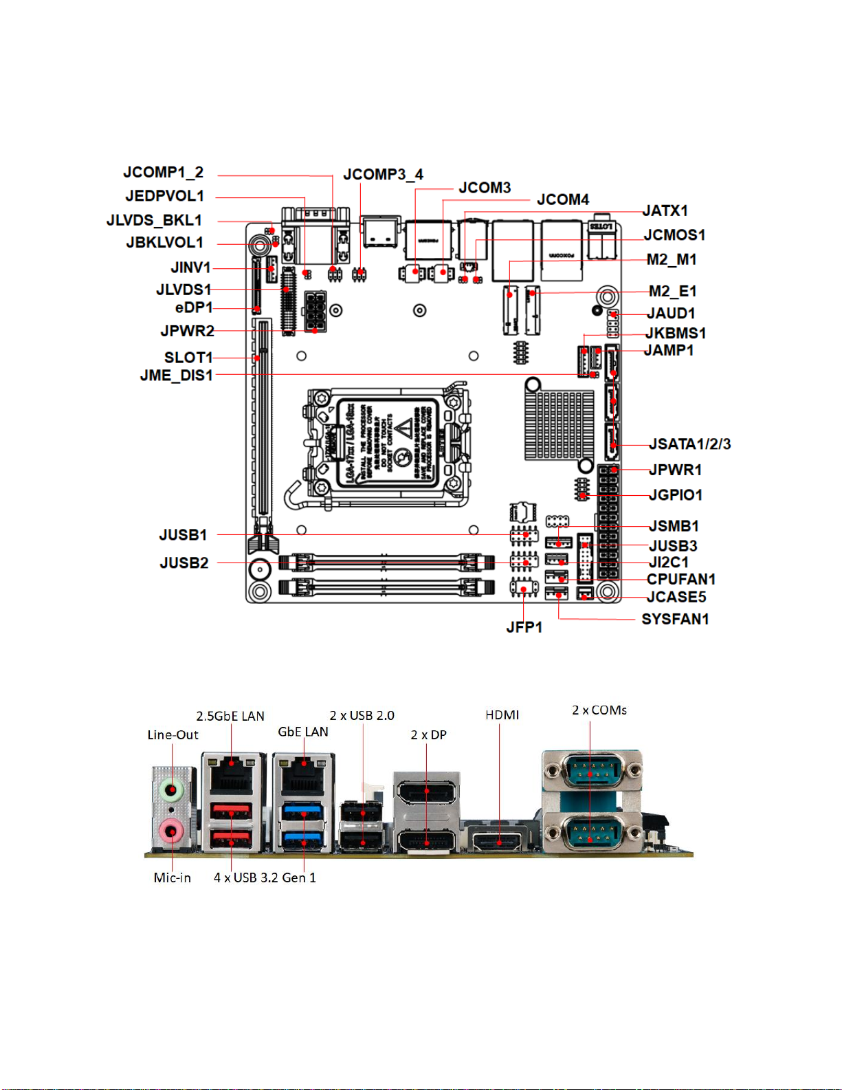
1.5.3 Mainboard Layout
• Back Panel:
18
1.5.4 Layout Content List
1.5.4.1 Slots
Label
Function
Note
Page
DIMM1
262-pin DIMM slot 1
If there is only one memory
module being installed in the
system, install it on this slot
first.
24
DIMM2
262-pin DIMM slot 2
24
SLOT1
PCI express x16 slot
43
M2_E1
2230 M.2 slot E Key
44
M2_M1
2280 & 2242 M.2 Slot M Key
44
1.5.4.2 Internal Jumpers
Label
Function
Note
Page
JCMOS1
Clear CMOS
1 x 3 header, pitch 1.25mm
38
JME_DIS1
Enable/disable the Intel ME F/W
1 x 3 header, pitch 1.25mm
41
JATX1
AT/ATX Power Select
1 x 3 header, pitch 1.25mm
40
JLVDS_BKL1
LVDS Backlight Control Select
1 x 3 header, pitch 1.25mm
42
JBKLVOL1
LVDS Backlight Power 3V/5V
Select
1 x 3 header, pitch 1.25mm
41
JEDPLVOL1
eDP Backlight Power 3V/5V
Select
1 x 3 header, pitch 1.25mm
40
JCOMP1_2
COM1 & COM2
RI/+5V/+12V Select
2 x 3 header, pitch 2.0mm
39
JCOMP3_4
COM3 & COM4
RI/+5V/+12V Select
2 x 3 header, pitch 2.0mm
39
JATX1
AT/ATX Power Select
1 x 3 header, pitch 2.0mm
40
1.5.4.3 Internal Headers
Label
Function
Note
Page
JPWR1
ATX-Power Connector
2 x 12 header
25
JPWR2
12V ATX-Power Connector
2 x 4 header
26

19
JSATA1/2/3
Serial ATA Connectors
7-pin
29
CPUFAN1
CPU Fan Connector
1 x 4 wafer, pitch 2.54mm
29
SYSFAN1
System Fan Connector
1 x 4 wafer, pitch 2.54mm
29
JI2C1
I2C
1 x 4 wafer, pitch 2.0mm
36
JSMB1
SMBus
1 x 4 wafer, pitch 2.0mm
37
JFP1
System Panel Connector
2 x 5 header, pitch 2.54mm
33
JCOM3
JCOM4
Serial Port Connector 3, 4
2 x 5 wafer, pitch 2.0mm
32
JGPIO1
Digital I/O header
2 x 5 header, pitch 2.0mm
34
JCASE5
Chassis Intrusion Connector
1 x 2 wafer, pitch 2.0mm
30
JKBMS1
PS/2 KB&MS
1 x 6 wafer, pitch 2.0mm
32
JUSB1
JUSB2
USB 2.0 Connector
2 x 5 header, pitch 2.54mm
31
JAMP1
Amplifier Connector
1 x 4 header, pitch 2.54mm
31
JUSB3
USB 3.2 Gen 1 Connector
2 x 10 Box header, pitch 2.0mm
34
JAUD1
Front Panel Audio Connector
2 x 5 header, pitch 2.54mm
31
JINV1
LVDS Inverter Connector
1 x 5 header, pitch 2.0mm
35
JLVDS1
LVDS Connector
2 x 20 header, pitch 1.25mm
35
eDP1
eDP Connector
1 x 40 header, pitch 0.5mm
36
1.5.4.4 Back Panel Connectors
Label
Function
Note
Page
AUDIO1
1 x Audio Dual Jack (Line-Out,
Mic)
17
Conn2
1 x 2.5GbE RJ45+Dual USB 3.2
Gen1 Stacked Connector
17
Conn1
1 x GbE RJ45 + Dual USB 3.2
Gen1 Stacked Connector
17
USB1
1 x Stack up USB 2.0 Connectors
17
DP1
1 x Stack up dual DisplayPort
Connector
17
HDMI1
1 x HDMI Connector
17
JCOM1
1 x Stack up dual COMs
Connector
17

20
1.5.4.5 Mating Connectors list
Connector/Header
Location
Mating P/N
Connector/Header P/N
Amplified Speakers
JAMP1
JST PHR-4 or equivalent
HORNG TONG
WF04N22DJF006
Backlight
JINV1
JST PHR-5 or equivalent
HORNG TONG
WF05N22WJQ006
COM Port
JCOM3; JCOM4
JST PHDR-10VS or
equivalent
HORNG TONG
WF10N63WAA210
eDP
EDP1
I-PEX 20453-040T-11
HIROSE KN38A-40S-0.5H(800)
Fan
CPUFAN1;
SYSFAN1
Molex 470541000 or
equivalent
HORNG TONG
WF04R2JDJQ113
Front Audio
JAUD1
Molex 22-55-2101 or
equivalent
HORNG TONG
PH10R52BAJ008
Front Panel
JFP1
Molex 22-55-2101 or
equivalent
HORNG TONG
PH10R63YAAB18
GPIO
JGPIO1
Molex 51110-1250 or
equivalent
HORNG TONG PH10N6-
7BAAA00
I2C
JI2C1
JST PHR-4 or equivalent
HORNG TONG
WF04N22DJF006
Keyboard/Mouse
JKBMS1
JST PHR-6 or equivalent
HORNG TONG
WF06N22WJJ006
LVDS
JLVDS1
Hirose DF13-40DS-
1.25C(10) or equivalent
HORNG TONG WF40H6-
7BAA178
SMB
JSMB1
JST PHR-5 or equivalent
HORNG TONG
WF05N22WJF006
USB 2.0
JUSB1; JUSB2
Molex 22-55-2101 or
equivalent
HORNG TONG
PH10R93BAAC09
USB 3.2 Gen 1
JUSB3
Molex 51110-2051 or
equivalent
HORNG TONG
BH20NQ3GAFL14
Table of contents
Other BCM Motherboard manuals


