BCSI pH SAFE PH1000 User manual

pH SAFE
TM
Reader
Model: BCSI pH1000
Operator Manual
Doc. No. 120001-09
Blood Cell Storage, Inc.
4203 23rd Ave W
Seattle, WA 98199 SA
MedEnvoy Global B.V.
Prinses Margrietplantsoen 33 - Suite 123
2595 AM The Hauge
The Netherlands
© 2022 All Rights Reserved
M
P
C
V


pH SAFE Reader Operator Manual - Doc. No. 120001-09
Table of Contents
1 Introduction . . . . . . . . . . . . . . . . . . . . . . . . . . . . . . . . . . . . 1
1.1 Intended Use ......................................................................... 1
1.2 Using this Manual ................................................................. 1
1.3 Warnings ............................................................................... 2
1.4 Precautions ........................................................................... 3
1.5 Informational Symbols ......................................................... 3
1.6 Limited Warranty .................................................................. 5
1.7 Trade Marks and Intellectual Property ................................ 6
2 System Description . . . . . . . . . . . . . . . . . . . . . . . . . . . . . . 7
2.1 Theory of Operation ............................................................. 7
2.2 Reader Components ............................................................ 8
2.3 Specifications ..................................................................... 10
3 Unpacking and Installation . . . . . . . . . . . . . . . . . . . . . . . 12
3.1 Unpacking ........................................................................... 12
3.2 Hardware Installation ......................................................... 12
3.2.1 Materials Required ...................................................................12
3.2.2 Procedure .................................................................................13
3.3 Software Setup ................................................................... 11
3.3.1 Configure pH SAFE Reader Options........................................11
4 Using the pH SAFE Reader Software. . . . . . . . . . . . . . . 14
4.1 Overview .............................................................................. 14
4.1.1 Power-On Self Check (SELF-CHK) ..........................................14
4.1.2 Run / Options Prompt ...............................................................15
4.1.3 Power Down .............................................................................15
4.2 Keypad Usage ..................................................................... 16
4.3 Bar Code Scanner Usage ................................................... 17
4.4 Software Security ............................................................... 17
4.4.1 Security Access to ‘Run Test’...................................................17
4.4.2 Security Access to ‘Options / System Settings’ ........................18
5 Run Test Operation . . . . . . . . . . . . . . . . . . . . . . . . . . . . . 19
5.1 Overview .............................................................................. 19
5.2 Security Access .................................................................. 19
5.2.1 Select/Enter User ID .................................................................19
5.2.2 Enter User PIN .........................................................................21
5.3 Enter Platelet Storage Bag ID ............................................ 22
5.4 Enter pHID ............................................................................ 23
5.5 Read pH ............................................................................... 24
5.6 Save/Print Test Results ...................................................... 25
5.6.1 Save pH................................................................................... 26
5.6.2 Print pH.....................................................................................27
5.6.3 Save & Print pH ........................................................................28
5.6.4 Discard Result ..........................................................................28

Table of Contents
pH SAFE Reader Operator Manual - Doc. No. 120001-09
5.7 Automatic Ethernet Results Upload ................................. 28
6 Using the Options Menu . . . . . . . . . . . . . . . . . . . . . . . . . 30
6.1 Overview .............................................................................. 30
6.2 Log Off User ........................................................................ 30
6.3 View Records ...................................................................... 31
6.3.1 pH Test Results List .................................................................31
6.3.2 Print Record?............................................................................32
6.3.3 Delete Record?.........................................................................33
6.4 Output Records .................................................................. 33
6.4.1 Select Records to Output .........................................................34
6.5 System Settings .................................................................. 37
6.5.1 System Menu............................................................................38
6.5.2 Supervisor PIN .........................................................................38
6.5.3 Set Clock ..................................................................................40
6.5.4 Enable User ID and PIN ...........................................................40
6.5.5 Edit User ID/PIN .......................................................................41
6.5.6 Erase Memory ..........................................................................42
6.5.7 Pack Memory............................................................................43
6.5.8 Ethernet Setup..........................................................................44
6.5.9 Read Ratio................................................................................46
6.5.10 Set QC Values........................................................................48
6.5.11 Set User Correction Values ....................................................49
6.5.12 Print Service Report ...............................................................49
6.5.13 Exit System Settings...............................................................50
6.6 Run QC Test......................................................................... 50
6.7 Exit Options ........................................................................ 50
7 Maintenance . . . . . . . . . . . . . . . . . . . . . . . . . . . . . . . . . . . 51
7.1 Daily Fiber Optic Probe Tip Inspection ............................ 51
7.2 Quality Control Test ........................................................... 52
7.3 Routine Cleaning ................................................................ 54
7.4 Disposal Precautions .......................................................... 54
8 Troubleshooting. . . . . . . . . . . . . . . . . . . . . . . . . . . . . . . . 55
8.1 BCSI Technical Support...................................................... 55
8.2 Error Messages ................................................................... 55
Appendix A Power-On Self Check (SELF-CHK) 57
A.1 pH SAFE Reader Calibration Self-Test.............................. 57
A.2 Real-Time Clock Test.......................................................... 57
A.3 Initialization of Ethernet Module 58
Appendix B Serial Port Results Upload 59
Appendix C Ethernet Setup 60

Chapter 1 Introduction
pH SAFE Reader Operator Manual - Doc. No. 120001-09 1
1 Introduction
1.1 Intended Use
The pH SAFE Reader (Sterile, Automated Fluoroscopic Evaluation) is an in
vitro diagnostic (IVD) medical device that provides a rapid, non-invasive method
to measure the pH of fluid contained in platelet storage bags. The pH SAFE
Reader (Model: BCSI pH1000) reports the pH at a temperature of 22°C.
Platelets collected in storage bags retain function over time. During storage of
platelets, the pH of the fluid in a platelet storage bag will change over time.
Regular pH monitoring of stored platelet units can be used to verify the quality
of platelet units before use in transfusion.
Current guidelines for acceptable pH range of stored platelets are established by
the Council of Europe, the International Society of Blood Transfusion (ISBT),
and the AABB. sers should refer to local protocols for additional guidance on
pH measurement.
The pH SAFE Reader is intended for use in hospital laboratories and blood
banks to monitor pH of platelet storage bags. Intended users are trained
laboratory and blood bank personnel; device is not intended for self-testing by
lay-users.
1.2 Using this Manual
Chapters in this manual provide comprehensive information describing the
technology and operation of the pH SAFE Reader:
Chapter 1 Introduction – (this chapter) contains introductory, safety, and
warranty information.
Chapter 2 System Description – contains a description about the principles of
the device technology, the components of the system, and the system
specifications.
Chapter 3 Unpacking and Installation – contains installation and setup
information.
Chapter 4 Using the pH SAFE Reader Software – contains a description of
the BCSI software application structure and detailed usage and configuration
information for all software features.
Chapter 5 Run Test Operation – contains instructions for performing the
specific tasks required for the typical daily use of the pH SAFE Reader.
Chapter 6 Using the Options Menu – contains procedures used to configure
and use functions available from the Options Menu.
Chapter 7 Maintenance – contains a description of the recommended
maintenance and quality control test procedures.
Chapter 8 Troubleshooting – contains BCSI Service and Technical Support
contact information and a list of possible error messages with a description of
the probable cause for each message and suggested resolution procedures.

1.3 Warnings
Chapter 1 Introduction
2 pH SAFE Reader Operator Manual - Doc. No. 120001-09
Appendix A Power-On Self Check (SELF-CHK)
Appendix B Serial Port Results Upload
Appendix C Ethernet Setup
1.3 Warnings
Conventions
Shock Potential when Power Improperly Applied
Ensure that the system is connected to a power receptacle that provides voltage
and current within the specified operating range. se of an incompatible power
source may produce electrical shock and fire hazards.
Shock Potential from Spilled Liquids
If liquid is spilled onto the instrument, fluid seepage into internal components
creates a potential shock hazard. If liquid is spilled onto the instrument,
disconnect power and clean/dry the instrument surfaces.
Do Not Remove Instrument Cover
The pH SAFE Reader contains no user-serviceable components. The
manufacturer warranty is voided if the instrument cover is removed.
Use only Supplied AC Power Adapter Cables for pH SAFE Reader and
Printer
A power adapter is supplied for specific use with the pH SAFE Reader. If the
optional Printer accessory will be used, an additional power adapter is also
supplied for specific use with the Printer.
DO NOT interchange the pH SAFE Reader and Printer AC power adapters.
Always ensure the proper supplied AC power adapter is used for each device.
Failure to do so may result in damage to the instrument and/or the Printer.
Ensure Instrument Power is OFF before connecting Bar Code Scanner
DO NOT connect the Bar Code Scanner to the pH SAFE Reader after the
instrument is turned ON. Doing so may result in damage to the Bar Code
Scanner.
This symbol indicates a potential hazard where misuse of the
system could result in damage to the equipment.
This symbol indicates a potential hazard where misuse of the
system could result in electric shock or fire.
!
!
!
!

1.4 Precautions
Chapter 1 Introduction
pH SAFE Reader Operator Manual - Doc. No. 120001-09 3
1.4 Precautions
Read the entire contents of this Operator Manual prior to using the pH SAFE
Reader.
Observe the following precautions when operating the pH SAFE Reader:
• nplug the instrument before cleaning.
• Clean only external surfaces using 70% ethanol or a mild detergent or non-
organic laboratory disinfectant and a damp cloth. DO NOT SE STRONG
BLEACH (> 0.1% solution) OR ORGANIC SOLVENTS!
• se only BCSI supplied or approved platelet storage bags with the pH
SAFE Reader.
• If the instrument is used in a manner not specified by the installation/
operation procedures included in this manual the safety protections
provided by the equipment may be impaired.
1.5 Informational Symbols
The following informational symbols are displayed on the pH SAFE Reader
and the pH SAFE Reader Quick Reference Guide.
Symbol Location Meaning
Bottom
Instrument Panel
CA TION: Electric Shock Hazard. Refer servicing to
qualified personnel. Consult accompanying documents.
|Power Switch
(Right Side Panel) On (Power Supply)
0Power Switch
(Right Side Panel) Off (Power Supply)
Quick Reference
Guide Power Switch with | (On) and o (Off)
Quick Reference
Guide
Put the pH sensor all the way onto the probe until a
click sound or feeling.
Quick Reference
Guide Inspect the probe for scrapings (see Chapter 7.1)
!
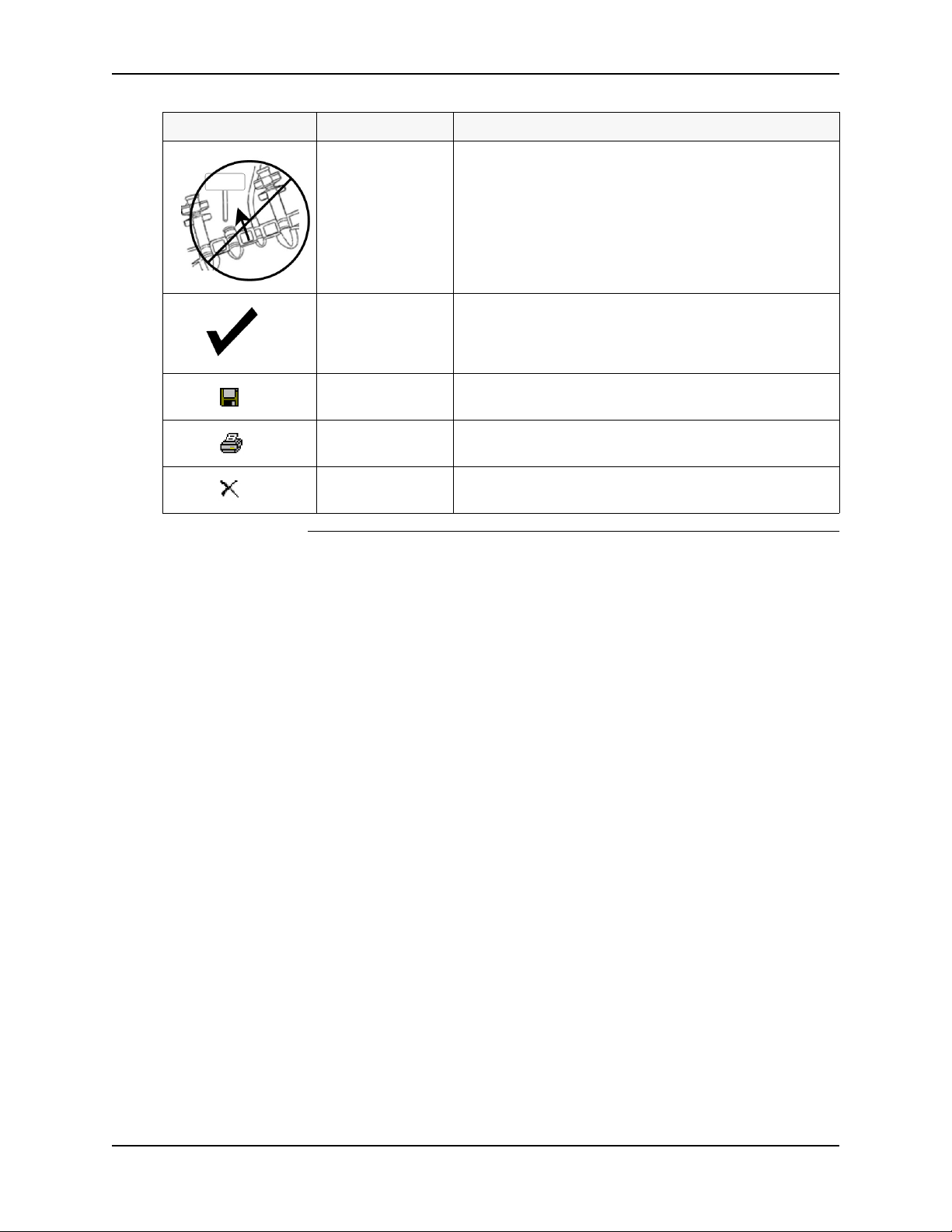
1.5 Informational Symbols
Chapter 1 Introduction
4 pH SAFE Reader Operator Manual - Doc. No. 120001-09
Symbol Location Meaning
Quick Reference
Guide
Ensure pH SAFE Sensor is aligned with fiber optic
probe on pH SAFE Reader. Avoid scraping the sensor
on the probe.
Quick Reference
Guide
Check the information on the pH SAFE Reader Screen
and the barcoded information for correct barcode
scanning or keyboard entry.
Quick Reference
Guide Save the pH Record
Quick Reference
Guide Print the pH Record via the RS 232 Serial Port
Quick Reference
Guide Delete the pH Record

1.6 Limited Warranty
Chapter 1 Introduction
pH SAFE Reader Operator Manual - Doc. No. 120001-09 5
1.6 Limited Warranty
Blood Cell Storage, Inc. (BCSI) warrants that, at the time of shipment, the
instrumentation provided to the customer is free from defects in material and
workmanship.
This limited warranty is conditioned upon the customer giving BCSI notice of
any defect within one (1) year after shipment. This limited warranty will not
apply if the instrumentation (a) has not been installed, used, or maintained in
accordance with applicable instructions and manuals; (b) has been repaired or
altered by unauthorized persons or misused, abused, accidentally damaged or
subjected to operation for which it was not intended; or (c) has had its serial
number altered or removed. This limited warranty does not apply to consumable
items. Except as expressly stated herein, BCSI makes no other warranties,
express or implied, including warranties of merchantability or fitness for
particular purpose.
nder this limited warranty, BCSI at its option, will repair or replace any
defective instrumentation. This is the sole remedy for any breach of warranty.
Any instrumentation to be returned for repair or replacement must be properly
packaged and shipped via prepaid freight in accordance with BCSI instructions.
This limited warranty does not apply to the use of the instrument other than as
described herein.
This limited warranty contains BCSI's sole obligation and liability related to the
customer's use of the BCSI products. .BCSI shall not be liable to the customer
for any other remedies of damages, including special, indirect, incidental, and
consequential damages, including, but not limited to, lost profits, whether based
upon warranty, strict liability, tort, contract or otherwise. This limited warranty
may not be changed in any way without the express written permission of BCSI.
Each provision of this agreement that provides for a limitation of liability,
disclaimer of warranties, or exclusion of damages is to allocate the risks between
the parties. This allocation is reflected in the pricing offered by BCSI to the
customer and is an essential element of the basis of the bargain between the
parties. Each of these provisions is severable and independent of all other
provisions of this agreement. The limitations in this section will apply
notwithstanding the failure of essential purpose of any limited remedy in this
agreement.

1.7 Trade Marks and Intellectual Property
Chapter 1 Introduction
6 pH SAFE Reader Operator Manual - Doc. No. 120001-09
1.7 Trade Marks and Intellectual Property
pH SAFE® and BCSI "…it's in the bag"® are registered S, Canadian and/or
European trademarks. The pH SAFE technology is covered by multiple issued
and pending S and International equivalent Patents including but not limited
to: S Pat. No. 7,608,460, 7,968,346, 8,148,167, 8,183,052, 8,497,134, 9,040,307,
9,062,205, 9,217,170; A Pat. No. 2005277258; JP Pat. No. 5017113; CN Pat.
No. ZL200580033961.1; IN Pat. No. 257667

Chapter 2 System Description
pH SAFE Reader Operator Manual - Doc. No. 120001-09 7
2 System Description
2.1 Theory of Operation
The pH SAFETM (Sterile, Automated Fluoroscopic Evaluation) technology is
based upon the principle that fluorescent dyes emit characteristic wavelength
spectra at different pH levels.
BCSI Platelet
Storage Bags
Concentrated platelets, a cellular component of blood, are stored in BCSI
Platelet Storage Bags intended for specific use with the pH SAFE Reader.
BCSI Platelet Storage Bags are manufactured to be identical to standard
platelet storage bags, in form and function, while providing an additional,
embedded pH SAFE Sensor. This port allows non-invasive pH monitoring of
the fluid in the bag using the pH SAFE Reader.
NOTE:
BCSI Platelet Storage Bags may be used in exactly the same manner as
standard platelet storage bags for platelet collection and transfusion
purposes. Refer to the BCSI Platelet Storage Bag package insert for
complete information about the characteristics and intended use of
the BCSI Platelet Storage Bags.
Figure 2-1 BCSI Platelet Storage Bag and pH SAFE Sensor
pH SAFE Sensor
The pH SAFE Sensor is a modified optical cuvette component which allows
non-invasive insertion of a Fiber Optic Probe and provides a special membrane
located at the lower end of the sensor. The membrane is impregnated with a
fluorescent dye which emits a characteristic wavelength spectra at different pH,
sealed inside the bag and immersed in the fluid contained by the bag. The dyed
membrane is positioned adjacent to a transparent optical window such that
fluorescent light emitted by the dye can be measured by the pH SAFE Reader
without removing any fluid, opening the bag, or otherwise compromising the
bag integrity and sterility of the platelet product.
pH SAFE
Sensor
Optical
Window
Dyed
Membrane
2.2 Reader Components
Chapter 2 System Description
8 pH SAFE Reader Operator Manual - Doc. No. 120001-09
pH SAFE Reader
Model: BCSI pH1000 To measure pH, the Fiber Optic Probe of the pH SAFE Reader is inserted
into the pH SAFE Sensor of the BCSI platelet storage bag. When directed by the
user, the Fiber Optic Probe delivers flashes of green light from a monochromatic
light source to the bag to excite and induce fluorescent light emission from the
dye in the membrane. When excited to fluorescence the dye produces a
characteristic wavelength spectrum of emission light. At one wavelength (600nm,
Fp), the intensity of light emission is variable and dependent upon the pH of the
fluid in the bag. At a second reference wavelength (568nm Fr), the relative
emission intensity is constant regardless of the pH of the fluid in the bag.
The intensities of the two wavelengths of interest are collected by photodetectors
in the pH SAFE Reader. A ratio of the two wavelengths is calculated and
converted into a pH. By using a ratio of the emission intensities, the pH can be
determined independent of factors such as excitation intensity, optical
transmission quality, or dye concentration. If either the intensity measurement or
the calculated ratio value fall outside acceptable ranges, an alarm message is
displayed on the instrument screen and the pH result value for this bag is not
stored.
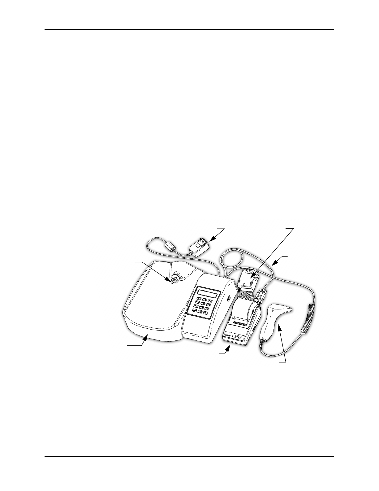
2.2 Reader Components
Figure 2-2 pH SAFE Reader Components
The pH SAFE Reader consists of the following components:
•pH SAFE Reader (Model: BCSI pH1000), power adapter (GlobTek, GT-
41052-1509), Ethernet cable, RS-232 Serial cable
• Bar Code Scanner
• Printer, power adapter, RS-232 Serial adapter (optional)
These individual components are described next.
Probe
pH SAFE Reader
RS-232
Model: BCSI pH1000
Fiber Optic
Power Adapter
Instrument
Printer
Bar Code Scanner
Power Adapter
Printer
Cable

2.2 Reader Components
Chapter 2 System Description
pH SAFE Reader Operator Manual - Doc. No. 120001-09 9
pH SAFE Reader
Model: BCSI pH1000
The pH SAFE Reader is a fluorometric instrument which includes the
following:
•Fluorometer - The instrument includes internal optical components used
for photometric measurement, an excitation light source, and a Fiber Optic
Probe, which is inserted into the pH SAFE Sensor in the Platelet Storage
Bag being tested, to deliver excitation light to induce fluorescence and
subsequently collect resulting emission light at 568nm and 600nm.
•System Software - The system software includes a user interface which
displays information on the liquid crystal display (LCD) screen and is
directed by the user via the keypad, data analysis functions, and a database
for storing ser ID and pH test results information.
•Communication Capability - The instrument provides the following
connection ports for data transfer with external devices:
- Bar Code Scanner port, for data entry of bar-coded platelet storage
bag ID and ser ID information.
- Keypad, for data entry of platelet storage bag ID and ser ID
information and menu navigation.
- RS-232 Serial port, for output of results data to a Printer, or for
upload of results data to an external personal computer (PC) or
laboratory information system (LIS).
- Ethernet port, for upload of results to an external PC or LIS.
Bar Code Scanner A handheld Bar Code Scanner device may be used to enter platelet bag ID and
ser ID information from bar codes. The Bar Code Scanner will be provided
with the pH SAFE Reader if appropriate for use in your facility.
The Bar Code Scanner is pre-configured to identify the ISBT 128 platelet storage
bag ID character format and ser ID bar code symbologies.
The Bar Code Scanner is connected to the Bar Code Scanner port provided on
the back panel of the instrument. The Bar Code Scanner is continuously
powered via the Bar Code Scanner port, but the instrument will only accept data
sent by the Bar Code Scanner at certain times during the measurement
procedure.
Printer An optional Citizen iDP-3110 Printer can be connected to the RS-232 Serial port
to generate a printed results report containing pH results for one or more tested
platelet storage bags.

2.3 Specifications
Chapter 2 System Description
10 pH SAFE Reader Operator Manual - Doc. No. 120001-09
2.3 Specifications
Dimensions
L x W x H
35 cm x 39.5 cm x 11 cm
(13.8 in x 15.5 in x 4.3 in)
Weight
2.35 kg (5.2 lbs)
External Connections
• PS2, for Bar Code Scanner
• RS-232 DB-9 (male), for serial communication
• Ethernet
Power Requirements
(AC Power Adapter)
Input power to power adapter:
• 100 - 240V AC, 50 - 60Hz, 0.6A max, 15W max
• Main supply voltage fluctuations must not exceed
±
10% of
nominal value
• Transient over voltages typically present on the main supply is
expected to be impulse withstand (over voltage) category II of
IEC 60364-4-443
Adapter output power: 9V DC, 1.7A max
(NOTE: Input connectors are available for: Continental Europe,
the nited Kingdom, North America and Australia)
Operating Temperature Range
5 - 40°C (41 - 104°F)
Operating Humidity Range
5 – 80% relative humidity, non-condensing
Operating Altitude
Maximum altitude 2000 m (6562 ft)
Pollution Degree Classification
Pollution Degree 2
Operating Environment
The instrument is intended for indoor use only
Transport and Storage
Conditions
Temperature: -10 - 50ºC (14 - 122ºF)
Humidity: 5 - 98% relative humidity, non-condensing
Atmospheric pressure: 50 kPa - 106 kPa (0.5 atm - 1 atm)
Keypad
10 character alphanumeric keys
2 special function keys
Display
2 line by 20 character Liquid Crystal Display (LCD)

2.3 Specifications
Chapter 2 System Description
pH SAFE Reader Operator Manual - Doc. No. 120001-09 11
Compliance with Standards
The
pH SAFE Reader
is in compliance with medical device
equipment operation requirements as specified in the following
regulatory standards documents:
• CAN/CSA-C22.2 No. 61010-1-04 - Safety requirements for
Electrical Equipment for Measurement, Control, and
Laboratory se - Part 1: General Requirements
• L Std. No. 61010-1 - Safety requirements for Electrical
Equipment for Measurement, Control, and Laboratory se -
Part 1: General Requirements
• IEC 61010-1 - Safety requirements for Electrical Equipment
for Measurement, Control, and Laboratory se - Part 1:
General Requirements
• EN 61010-1 - Safety requirements for Electrical Equipment
for Measurement, Control, and Laboratory se - Part 1:
General Requirements
• CAN/CSA-C22.2 No. 61010-2-101-04 - Safety Requirements
for Electrical Equipment for Measurement, Control and
Laboratory se - Part 2-101: Particular Requirements for In
Vitro Diagnostic (IVD) Medical Equipment
• IEC 61010-2-101 - Safety Requirements for Electrical
Equipment for Measurement, Control and Laboratory se -
Part 2-101: Particular Requirements for In Vitro Diagnostic
(IVD) Medical Equipment
• EN 61010-2-101 - Safety Requirements for Electrical
Equipment for Measurement, Control and Laboratory se -
Part 2-101: Particular Requirements for In Vitro Diagnostic
(IVD) Medical Equipment
• EN 61326-1 - Electrical Equipment for Measurement, Control
and Laboratory se - EMC Requirements

Chapter 3 Unpacking and Installation
12 pH SAFE Reader Operator Manual - Doc. No. 120001-09
3 Unpacking and Installation
3.1 Unpacking
The pH SAFE Reader is shipped in one (1) box, as follows
Box 1 contains:
• 1 - pH SAFE Reader (Model: BCSI pH1000)
• 1 - pH SAFE QC Standard
• 1 - Instrument power adapter
• 1 - Ethernet cable
• 1 - Instrument to printer serial cable
• 1 - pH SAFE Reader Operator Manual
• 1 - pH SAFE Reader Quick Reference Guide
• 1 - Bar code scanner box, containing: the Bar Code Scanner and the Bar
Code Scanner U er’ Manual.
If the optional Printer is purchased, a second box will also be shipped.
Box 2 contains:
• 1 - Printer box, containing: the Printer, the printer power adapter,
printer paper, ink ribbon, and the printer U er’ Manual.
• 1 - Serial cable adapter
After unpacking all components, save the packaging materials and boxes for
reuse in the unlikely event that it is necessary to return any damaged
components.
3.2 Hardware Installation
3.2.1 Materials Required
1 - pH SAFE Reader and power adapter
1 - Printer and power adapter (optional)
1 - Bar code scanner
1 - Instrument to printer serial cable and adapter (optional)
1 - Ethernet cable

3.3 Software Setup
Chapter 3 Unpacking and Installation
pH SAFE Reader Operator Manual - Doc. No. 120001-09 13
3.2.2 Procedure
Refer to the figure below and perform the following steps:
Figure 3-1 Hardware Connections
1. Position the pH SAFE Reader so that the power adapter(s) can be quickly
disconnected from the facility AC power source if necessary in the unlikely
event of an electrical fire.
CAUTION: se only the supplied power adapters for the pH SAFE Reader
and the (optional) Printer device.
DO NOT interchange for use the pH SAFE Reader and Printer
AC power adapters. Always ensure the proper AC power adapter is
used for each device. Failure to do so may result in damage to the
instrument and/or the Printer.
2. Connect the instrument power adapter to the Power Input port on the back
panel of the instrument and to the facility AC power source.
3. If the Bar Code Scanner will be used, connect the Bar Code Scanner to the
Bar Code Scanner port of the instrument.
4. If the optional Printer will be used, connect the Printer to the RS-232 Serial
port of the instrument using an RS-232 cable. Connect the Printer power
adapter to the Printer and to the facility AC power source.
5. If an Ethernet connection will be used, connect an Ethernet cable from the
external PC, or Ethernet drop wall jack, to the Ethernet port of the
instrument.
3.3 Software Setup
3.3.1 Configure pH SAFE Reader Options
Before using the pH SAFE Reader, configure the System Settings parameters
as desired. Refer to Section 6.5, System Settings.
pH SAFE Reader (Rear Panel)
to LIS
to
Bar Code Scanner
pH SAFE Reader
to
Power Adapter
to
Printer or PC
!

Chapter 4 Using the pH SAFE Reader Software
14 pH SAFE Reader Operator Manual - Doc. No. 120001-09
4 Using the pH SAFE Reader Software
4.1 Overview
Figure 4-1 pH SAFE Reader Screen and Keypad
From the pH SAFE Reader the user observes information displayed on the
LCD screen and manipulates the pH SAFE Reader software functions using
the keypad. Additionally, at appropriate times during the testing process, the user
may use the Bar Code Scanner to input platelet storage bag ID and ser ID
information if desired.
The LCD screen displays current software function status information and
updates automatically to report: function progress/completion, and response to
input by the user from either the keypad or the Bar Code Scanner.
4.1.1 Power-On Self Check (SELF-CHK)
Whenever power is applied to the instrument using the ON/OFF switch
(located on the right side panel of the instrument, Figure 2-2) the software
executes a startup sequence, the Power-On Self Check (SELF-CHK). This
automatic test completes in 5 seconds. During SELF-CHK the keypad is
inactive. The sequence of the SELF-CHK is as follows:
1. First the LCD screen pixels are exercised. All screen pixels are turned on for
one second. The screen should display two rows of 20 black squares
indicating all pixels are functioning in each character block.
2. Next the LCD screen updates to display the Software Version information
while concurrently the software initializes the internal photometer hardware
components and performs a series of function tests to verify system
performance. (Refer to Appendix A for a full description of the SELF-CHK
test process, SELF-CHK error conditions, and SELF-CHK error recovery
procedures.)
LCD Display
Alphanumeric Keys
Up (
) Key Down (
) Key
Function Keys
*BLOOD CELL STORAGE*
pH1000 V.X.X

4.1 Overview
Chapter 4 Using the pH SAFE Reader Software
pH SAFE Reader Operator Manual - Doc. No. 120001-09 15
3. After the SELF-CHK procedure is complete the LCD screen updates to the
Ethernet setup screen. During Ethernet setup the instrument verifies that the
Ethernet module is functioning and synchronizes stored data.
When Ethernet setup is successfully concluded the LCD screen updates to
display the Run/Options prompt. se of the Run/Options prompt is described
next.
4.1.2 Run / Options Prompt
Whenever the Run/Options prompt is displayed on the LCD screen, the
instrument is in an idle state awaiting direction from the user.
From this screen the user may access the following functions:
Run Test - From the Run/Options prompt, when the <Enter> key is pressed the
instrument begins a pH measurement test. The LCD screen updates to
display a prompt to begin the measurement process. The Run Test process is
fully described in Chapter 5, Run Test Operation.
Options Menu - From the Run/Options prompt, when the <Options> key is
pressed the instrument enters the Options Menu. The Options Menu
provides access to a list of functions used to review/print results records and
configure system operation parameters. The LCD screen updates to display
access to the first function available from the menu. se of the Options
Menu functions is fully described in Chapter 6, sing the Options Menu.
Automatic Results
Upload
The system may be configured to automatically transfer results data to an
external computer or LIS via an Ethernet connection. If Ethernet
communication is setup from the Options/System Settings/Ethernet Setup
menu, the external computer or LIS can be configured to automatically upload
the test results stored in the instrument memory at periodic intervals. All
instrument functions behave normally when test results are being uploaded via
Ethernet except in the case where a new measurement test result is ready to be
saved. In this case the instrument will pause until the upload is complete
(typically the pause will be less than 2-3 seconds) before saving the latest test
result in the instrument memory. (Refer to Section 6.5.8, Ethernet Setup.)
Alternatively results may be uploaded to an external computer or LIS by output
through the serial port. (Refer to Appendix B, Serial Port Results pload, for
complete information.)
4.1.3 Power Down
To turn off the pH SAFE Reader ensure all testing or test uploading process
are complete, return to the Run/Options prompt, and toggle the ON/OFF
switch located on the right side panel of the instrument.
RUN TEST: <Enter>
OPTIONS: <Options>

4.2 Keypad Usage
Chapter 4 Using the pH SAFE Reader Software
16 pH SAFE Reader Operator Manual - Doc. No. 120001-09
4.2 Keypad Usage
The keypad consists of ten
alphanumeric character keys,
<0> - <9>, and two Function keys,
<Options> and <Enter>.
The alphanumeric keys are used to
enter ser ID/PIN, Supervisor PIN,
and platelet storage bag ID
information as needed.
The function keys are used to
navigate through the software and
manipulate the use of functions.
Entering
Alphanumeric
Characters
The alphanumeric keys are used to input a sequence of number and/or letter
characters when entering ser ID/PIN, Supervisor PIN, or platelet storage bag
ID information.
To input a specific letter or number, press the appropriate key multiple times to
scroll through the choices until the desired character is displayed. For example,
to input the letter R, press the key marked <PQR 6> four times, until the letter R
is displayed.
When the desired character is displayed, press a different alphanumeric key
(other than the key initially pressed) to accept the first character and move the
cursor one character position to the right for entry of the next desired character.
Alternatively, once the first desired character is displayed, wait, and after a two-
second delay the displayed character is accepted automatically and the cursor
moves one space to the right. This provides a means of entering double-letters or
double-digits.
Pressing the <Options> key causes the character currently displayed to be erased
and the cursor to move one space to the left. This provides a backspace or
correction function.
If either the <Options> or <Enter> key is pressed when no characters are shown
on the display, the test is aborted and the system returns to the Run/Options
prompt.
Scrolling Menu
Lists
Up Arrow
Down Arrow
At several points when using the software a menu of several function choices is
provided. The two line LCD display displays only one menu item at a time. To
scroll the display through choices available from a menu, use the Up Arrow key
<ABC 1> and the Down Arrow key <GHI 3> as necessary.
When a particular function is displayed on the screen, press the <Enter> key to
access use of that function.
RUN TEST: <Enter>
OPTIONS: <Options>
ABC
1
GHI
3
Table of contents
Popular Measuring Instrument manuals by other brands


Compu-Flow
Compu-Flow C6 quick start guide

Kestrel
Kestrel 2500 NV user guide

Orno
Orno OR-DC-633 instruction manual

Endress+Hauser
Endress+Hauser Proline Promag 10D technical information

National Instruments
National Instruments 9775 Getting started guide

CS-iTEC
CS-iTEC S 505 Instruction and operation manual


