Sourcetronic MPK-102e User manual

Formato: 135mm x 190mm
Digital micro-ohmmeter
• User guide
• T echnical specifications

MPK-102e
100 A digital micro-ohmmeter
User guide
GU-1576
3

Safety Precautions
Before to use this instrument the User guide and Safety precautions must be
read and understood.
This equipment should be operated only by qualified and duly trained people,
closely observing the corresponding safety regulations and instructions
contained in the present User Guide.
It should be checked that the item to be measured is voltage free.
Before starting with the measurements, be sure that the battery is well charged
and that the line voltage is between specified limits.
Do not connect or disconnect the test leads during the measurement.
There are no adjustable parts or parts that can be replaced by the user within the
equipment. Taking out the Control Panel in order to have an access to the
internal parts may be dangerous as there are high voltages inside, capable of
causing fatal accidents.
Cleaning of this instrument should be carried out using a soft cleaning liquid,
after verifying that it doesn't attack the plastic parts used in the case and in the
Control Panel of this equipment.
The protection obtained by the instrument can be compromised if it is used in a
way that is not described in this user guide.
When using the equipment, place it on a flat, stable surface so that the power
cord (if used) is easily accessible.
This equipment should be used only by a trained and
competent person, strictly applying suitable safety rules.
4

Used symbols
Caution, refer to User Guide.
Warning, hot surface: It indicates that the region covered by the mark
may become hot due to long periods of use of the equipment. Be careful
when handling.
Double insulation: this symbol indicates that the equipment is classified
as Class II, double insulation.
The rubbish bin with a line through it means that in the European Union,
the product must undergo selective disposal for the recycling of electric
and electronic material, in compliance with Directive WEEE 2002/96/EC.
30V MAX (to ground): indicates the maximum potential permitted to the
terminals during the measurement of the resistances.
Equipment complies with current EU Directives.
Thermal protection: with this LED lit indicates that the thermal protection
is activated.
Battery charging: LED lit in red indicates battery charging; LED
lit in solid green means battery fully charged.
5

Index
1.Description..............................................................................................................7
2.Operating principle..................................................................................................7
3.Operating instructions.............................................................................................7
3.1.Use of test probes............................................................................................7
3.2.Control panel....................................................................................................8
3.3.Power supply...................................................................................................9
3.4.Battery condition..............................................................................................9
3.5.Battery and charger.......................................................................................10
3.6.Measurement.................................................................................................11
3.7.Display messages..........................................................................................15
4.Some notes about accuracy.................................................................................16
5.Protections............................................................................................................17
5.1.Start with I = O...............................................................................................17
5.2.Temperature protection.................................................................................17
6.USB Drivers..........................................................................................................18
7.Maintenance..........................................................................................................19
7.1.Replacement fuse .........................................................................................19
7.2.Cleaning.........................................................................................................19
8.Technical specifications........................................................................................20
9.Warranty................................................................................................................22
6

1. Description
The SOURCETRONIC MPK-102e high-current micro-ohmmeter is a
portable, microprocessor-controlled instrument, used to accurately
measure very low contact resistances of breakers and switches, busbars,
transformers winding and engines, etc, with test currents from 1 mA to
100 A.
• Kelvin architecture (four-terminal method).
• Digital reading, alphanumeric display.
• Up to 4½ digits readings.
• Powered by rechargeable battery or mains supply.
• 0.1 µΩ resolution.
• 200 Ω maximum reading.
• Overheating protection.
2. Operating principle
This device uses the Kelvin Bridge architecture, with four terminals,
avoiding testing leads resistance to cause error during measurement.
Test current may be chosen by the operator and the reading is obtained
by comparison through internal high-stability standards. The result
appears in the alphanumeric display which is very easy to read.
3. Operating instructions
3.1. Use of test probes
Select the suitable test probes for the measurement you intend to perform
taking into account the current chosen for the test (Cables for up to 10 A
or 100 A). If you use the cables corresponding to 100 A, please verify that
the test probes are tightly fit in their corresponding connectors.
7

3.2. Control panel
On/Off switch.
Stop button.
Start button.
Hold button. It retains the last
measurement in the display.
Button to measure the Battery
charge condition.
Alphanumeric display that
shows both the measured
resistance value and messages to
the operator.
Power cord connector.
Fuse.
Ground.
100 A (C1) current output
terminal.
10 A (C1) current output terminal.
USB data output.
Potential (P1) terminal.
Potential (P2) terminal.
10 A (C2) current output terminal.
100 A (C2) current output
terminal.
Range and test current Selector
Battery charge led.
Thermal protection led.
Test Current control.
8

3.3. Power supply
Mains supply or internal battery powered
Battery: rechargeable, 12 V.
Internal battery is useful for up to 10 A.
Mains: 220 - 240 V~
Mains power is useful for any test current, including 100 A.
Make sure that the voltage of the mains supply is
compatible with the voltage supply of the equipment!
Before connecting the equipment to the mains supply, make
sure that the power cord is not damaged. If damaged, do not
connect the equipment to the mains supply and contact the
service center for replacing the power cord.
3.4. Battery condition
The charge condition of the battery can be verified before or during the
resistance measurement. In order to achieve that, the operator has to
press the battery button while the equipment is turned on. The bargraph
shows remaining charge as a percentile value.
If during measurement the charge of the battery achieves a critical level,
the display will show the BAT message notifying that the charge level is
low. After a few minutes the measurement will be automatically
interrupted in order to preserve the battery from a deep discharge that is
prejudicial for its expected useful life.
9

3.5. Battery and charger
Battery description
The SOURCETRONIC MPK-102e micro-ohmmeter uses a rechargeable
12 V battery.
Charging procedure:
Check that the On/Off key is OFF.
Connect the equipment to the mains supply.
The Battery charging indicator ( ) will keep on
lightning with a red light up to completing the charge. At that point, it will
change to a green light, being like this up to the equipment
disconnection from the mains supply.
Make sure that the voltage of the mains supply is
compatible with the voltage supply of the equipment!
At the end of battery useful life, the battery must be recycled or
disposed of properly, in order to protect the environment.
The rechargeable battery does not show the “memory effect” and there are no
restrictions to start charging it as many times as is needed. However the battery
could be damaged if remains in deep discharge for a while.
To avoid this effect, charge the battery before left the equipment in storage and
don’t let pass more than 30 days without recharge, even if the instrument wasn’t
used (under storage, the battery loses part of its charge).
10

3.6. Measurement
Warning
Before to use this instrument the User guide and Safety warnings must be read
and understood.
Safety procedures and rules for working near high voltage energized systems
must be observed during the use of this equipment. The generated voltages and
currents may be dangerous.
1. Before power-on the equipment, connect the test probes to the item to
be measured and to the front panel terminals, as shown in figure 2 for
current up to 10 A or in figure 3, for the 100 A range.
R
R
fig. 2
fig. 3
The clamps in the drawings are only for illustration.
11

2. Switch the equipment On using the
On/Off switch.
3. Using the Range selector, choose
the range and the current to use
4. Be sure that the Test current
control is at the start position
(counter-clockwise completely
rotated).
Otherwise, Start button will be
inhibited and the display will show
the message:
5. The PRESS START message will
appear showing that measurement
can be started.
12

6. Press the Start button.
The LOW CURRENT message will
turn up:
7. Turning the Test current control
clockwise, increase current until
obtaining the desired value or until
the current bargraph reads 100
divisions. The bargraph will show
the test current value as the
percentage of the nominal value
selected by using the Range
selector.
8. The equipment should be connected to the mains supply in order to
work with 100 A.
9. The lowest current for measuring is 10% of the range nominal value. It
is important to consider that the measurement errors increase while
test current decreases. The error is specified for test currents higher
than 80%.
10. The Display will show the resistance value measured and the unit
used (Ω [ohms], mΩ [milli-ohms] or µΩ [micro-ohms]).
11. The value can be retained in the
second line of the display by
pressing the button Hold. If you
press this button again, the value
will be erased.
13

12. Press the red button Stop in order
to finish the measurement.
13. Finally, when finishing
measurements, turn the equipment
off using the On/Off switch.
Precaution: Do not connect or disconnect the test leads during
the measurement. If you need to make any changes in the test
leads connections it must be done after pressing the Stop
button.
14

3.7. Display messages
SOURCETRONIC MPK102e
01020 10030 40 50 60 70 80 90
When turning the equipment on using the
On/Off switch, this introduction message
appears for a while.
This message appears each time the
equipment needs to adjust any parameter
in order to optimize the readings.
Warns the operator that to be able to start
a test, the Test current control must be
at the zero position (fully counter-
clockwise). Otherwise, Start button will be
inhibited.
The equipment is ready to start a
measurement, thus the operator has to
press the Start button.
Indicates that the test current is not
enough to carry out the reading. It
appears at the beginning of each test and
it keeps on being there up to the operator
rotates the Test current control
clockwise.
Indicates that the measured resistance is
higher than the maximum value readable
in the selected range.
Indicates that some part of the equipment
has achieved the critical temperature.
Thus the system will cut the high current
generation.
15

It appears at the second line of the
display, showing that the value is the one
retained in the display when pressing the
Hold button.
It shows that the battery is quite
discharged. It is necessary to recharge
the battery.
4. Some notes about accuracy
In order to obtain the specified accuracy, the operator has to adjust the
test current to a value higher than the 80% of the nominal value. If it were
necessary, it is possible to use a lower current, but by doing this the
accuracy will be affected.
MPK-102e has an auto-compensation system that automatically
eliminates the error produced by internal offset. Thus, it is not necessary
to carry out measurements by reversing the polarity in order to compute
the average value. Nevertheless, if the operator suspect that there is a
difference of temperature between the contact points that would can
generate thermoelectric voltages, it is necessary to carry out two
measurements by reversing the current cables and so, the circulation
sense of the current through the resistance under measurement. The
resistance value to be measured will be the average between the values
in one sense and in the contrary (direct and inverse current).
16

5. Protections
5.1. Start with I = O
Very quick variations of the current may cause damages to sensible
items. In order to avoid them, the equipment has a protection that
imposes to start the test with zero current. You can only start the
measurement if the current adjust control is at the start of its course. If
this were not the case, the Start would be inhibited and the message
would say START WITH I=O. If the operator sharply increases the test
current by quickly rotating the Test current control clockwise, the
equipment will impose a slow current growth, in order the current to softly
come to the selected value.
5.2. Temperature protection
The time of MPK-102e continuous use is limited by thermal
considerations. Some internal sensors measure the temperature of the
sensitive parts and trigger the protection that will cut the current
circulation, if any of them exceeds the limit temperature, thus avoiding
any damage. The Thermal protection led will light on and the
OVERHEATING message will appear in the display. Under these
conditions, measurements will be inhibited in the 100 A range.
Measurements in other scales may be carried out normally, though the
LED indicator keeps on being displayed up to the temperature decreases
sufficiently.
17

6. USB Drivers
1. Connect the equipment in the PC using the USB cable.
2. If there is an available Internet connection, Windows will silently
connect to the Windows Update website and install any suitable driver
it finds for the device. If no suitable driver is automatically found then
you need to download it from www.sourcetronic.com website. Run
the executable “usb-install.exe” and click in “Install”.
The USB output can be used to register measurements in a serial
communication software. The configurations are:
Baud rate: 4800 bps
8 bits - no parity - 1 stop bit (8,n,1)
Note: the resistance units are shown with the following symbols:
uR = micro-ohm
mR = milli-ohm
R = ohm
18

7. Maintenance
7.1. Replacement fuse
To replace the fuse, use only the fuse type specified in the
equipment.
Fuse specifications:
Fuse Schurter, model SPT 5 x 20 (Time-lag) 8 A / 250 V.
High breaking capacity.
1. Disconnect the equipment from the mains, unplugging the power cord.
2. With a screwdriver, remove the fuse holder cover, lightly pressing the
lid and turning ¼ counter clockwise.
3. Remove the blown fuse and insert a new fuse in the fuse holder
cover.
4. Place the cover in the compartment and with the screwdriver turn ¼
clockwise or until the fuse holder cover properly fits the fuse
compartment.
7.2. Cleaning
Cleaning of this instrument should be carried out using a soft cleaning
liquid, after verifying that it doesn’t affect the plastic parts used in the case
and in the Control Panel of this equipment.
To avoid electrical shock, make sure that the equipment is
completely dry before Power it On.
19

8. Technical specifications
Test currents : 1 mA, 10 mA, 100 mA, 1 A, 10 A, 100 A.
Each current may be continuously adjustable from
0 to 100%
Resistance ranges : Currents Range Resolution
100 A 0-199.9 µΩ 0.1 µΩ
100 A 0-1999 µΩ 1 µΩ
10 A 0-1999 µΩ 1 µΩ
10 A 0-19.999 mΩ 1 µΩ
1 A 0-19.99 mΩ 10 µΩ
1 A 0-199.99 mΩ 10 µΩ
100 mA 0-199.9 mΩ 100 µΩ
100 mA 0-1999.9 mΩ 100 µΩ
10 mA 0-1999 mΩ 1 mΩ
10 mA 0-19.999 Ω 1 mΩ
1 mA 0-19.99 Ω 10 mΩ
1 mA 0-199.99 Ω 10 mΩ
For each test current, ranges are automatically selected
for optimal reading.
Output voltage : Up to 10 Vd.c. @ 1 A (open circuit).
Measurement principle : Four-terminal, Kelvin-type.
Continuous operation time : At 100 A this equipment may be used continuously
for approx. 15 minutes before the thermal
protection activates.
At 10 A or less, there is not a limited time for
continuous operation.
Thermal protection : Protects all sensitive components, avoiding any
damage due to overheating.
Basic accuracy : R < 0.5 mΩ: ± (0.50% of reading + 2 ULSD*)
R ≥ 0.5 mΩ: ± (0.20% of reading + 2 ULSD*)
* Units of the Least Significant Digit.
Advanced features : Digital direct reading of very low resistances in the
alphanumerical display, with up to 4½ digits. Very
fast and accurate measurements.
Test current measurement : The current is digitally measured and a bargraph
shows the result. The bargraph indication is
especially useful when measuring inductive loads,
so that the operator can verify easily when the test
current has been stabilized.
20

Serial data output : USB
Environmental protection : IP54 with closed lid.
Safety class : Meets the requirements of IEC 61010-1.
Power supply : Mains or internal battery powered
Battery: rechargeable, 12 V.
Internal battery is useful for up to 10 A.
Mains: 220 - 240 V~
Mains power is useful for any test current, including
100 A.
Battery charger : 220 - 240 V~
Insulation : Class II
Pollution degree : 2
Overvoltage protection : Category II
Operating temperature
range
:-5°C to 50°C
Storage temperature range : -25°C to 65°C
Humidity range : 95% RH (non condensing)
Equipment weight : Approx. 14 kg.
Dimensions : 502 x 394 x 190 mm
Accessories : 2 Combined current and potential leads for 10 A
(1.8 m).
2 Combined current and potential leads for 100 A
(6 m).
1 Communication cable (USB).
1 Power cord.
1 User guide.
1 Case for the accessories.
To ensure safety, use only accessories supplied by the
manufacturer.
Subject to technical change without notice.
21
This manual suits for next models
1
Table of contents
Other Sourcetronic Measuring Instrument manuals
Sourcetronic
Sourcetronic ST2829A User manual

Sourcetronic
Sourcetronic MPK-2000e User manual
Sourcetronic
Sourcetronic ST2515 User manual
Sourcetronic
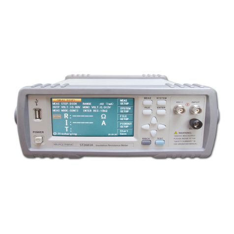
Sourcetronic ST2683A User manual
Sourcetronic
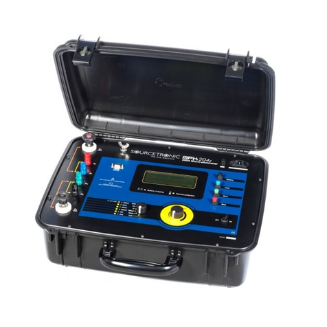
Sourcetronic MPK-204e User manual
Sourcetronic
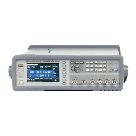
Sourcetronic ST2638 Series User manual
Sourcetronic
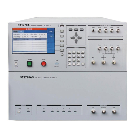
Sourcetronic ST1778A User manual
Sourcetronic
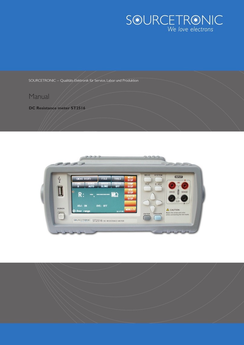
Sourcetronic ST2516 User manual
Sourcetronic
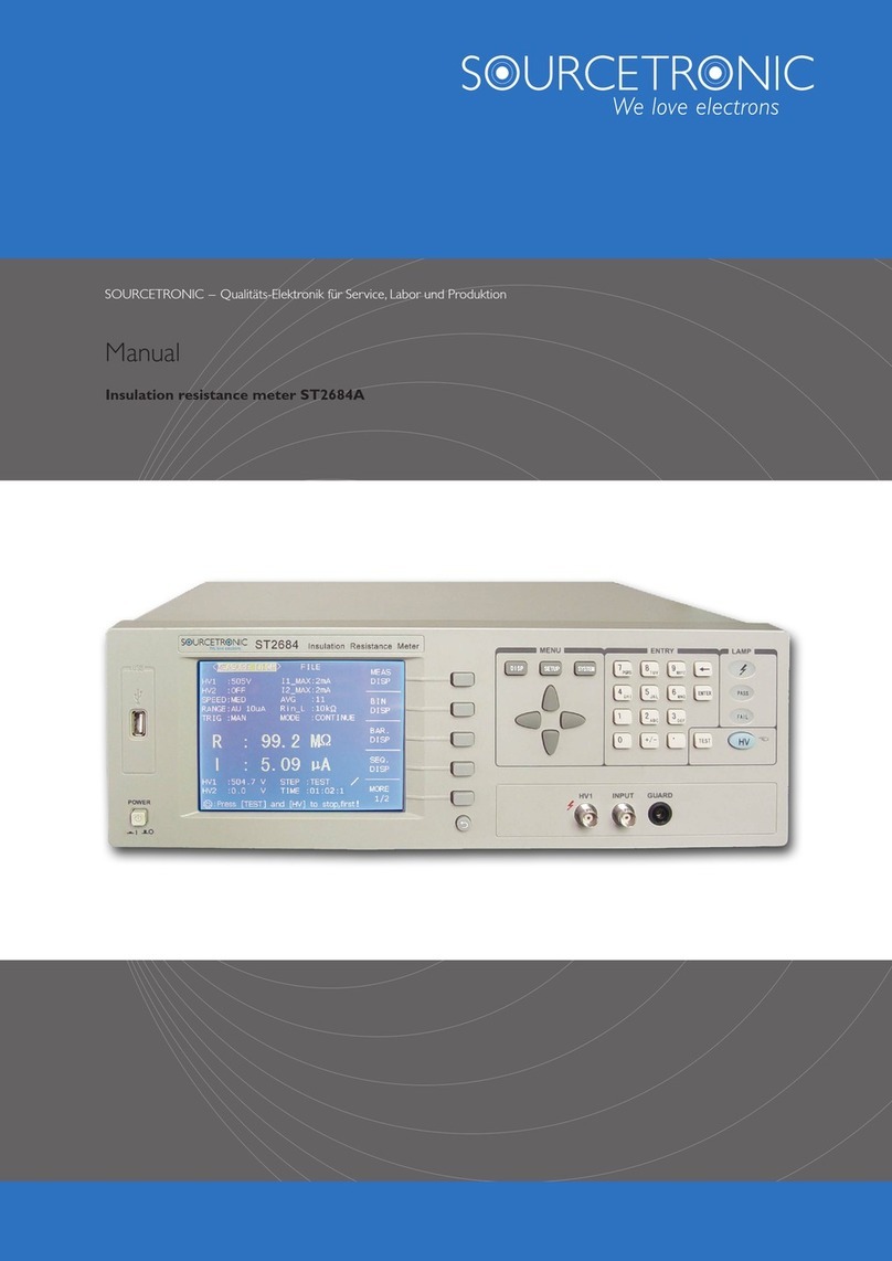
Sourcetronic ST2684A User manual
Sourcetronic
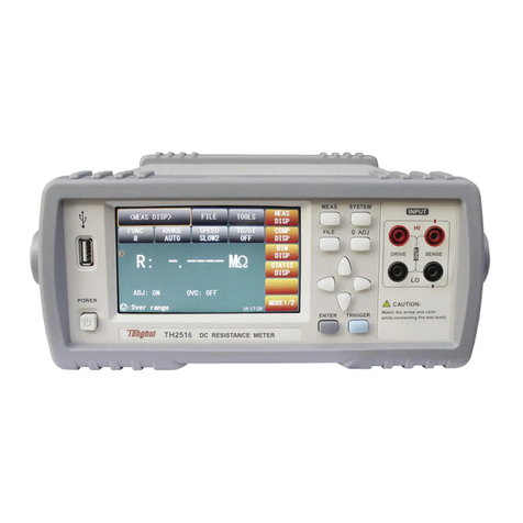
Sourcetronic TH2516 Series User manual
