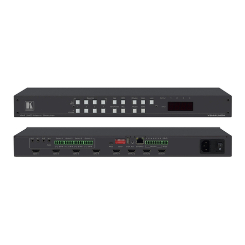
BDV CXPS User manual

CXPS Manual
Edition 1.07
August 10, 2011
BDV
BLACK DIAMOND VIDEO

Edition 1.07 CXPSManual
Trademarks
The Black Diamond Video logo and CXPS are registered trademarks of Black Diamond Video, Inc.
Warranty
Warranty and Warranty Disclaimer: Black Diamond Video warrants to the original purchaser ("Buyer") that the products
delivered by Black Diamond Video that accompany this manual ("Products") will be in accordance with Black Diamond
Video’s published specifications under normal use and service for a period of one (1) year from delivery. Deviations from
published specifications which do not materially affect performance of Products covered hereby shall not be deemed to
constitute defects of material or workmanship or a failure of Products to comply with such specifications. Warranty claims
and the return of Products under warranty shall be subject to, and governed by, Black Diamond Video’s return material
authorization (RMA) policy. This warranty shall not apply to any Product that has been subject to misuse or neglect or
damaged by weather or accident (including, without limitation, damage due to fall, fire, exposure to water and abnormal
electrical exposure), or that has been modified by anyone other than Black Diamond Video. The warranties contained herein
shall extend only to Buyer and shall not apply to Buyer’s affiliates or customers or subsequent purchasers. SELLER’S
ENTIRE LIABILITY, AND BUYER'S SOLE AND EXCLUSIVE REMEDY, SHALL BE LIMITED SOLELY TO
SELLER, AT ITS OPTION AND ELECTION, REPAIRING OR REPLACING THE DEFECTIVE PRODUCT.
WARRANTY CLAIMS MUST BE MADE WITHIN THE WARRANTY PERIOD OR ARE FOREVER WAIVED.
EXCEPT FOR THE EXPRESS WARRANTY MADE IN THIS PARAGRAPH, BLACK DIAMOND VIDEO
EXPRESSLY DISCLAIMS AND EXCLUDES ALL WARRANTIES, WHETHER STATUTORY, EXPRESS OR
IMPLIED, INCLUDING, BUT NOT LIMITED TO, THE IMPLIED WARRANTIES OF MERCHANTABILITY,
FITNESS FOR A PARTICULAR PURPOSE AND NON-INFRINGEMENT OF THIRD PARTY RIGHTS WITH
RESPECT TO THE PRODUCTS FURNISHED BY BLACK DIAMOND VIDEO HEREUNDER AND ALL
WARRANTIES WHICH, BUT FOR THIS PROVISION, MIGHT ARISE FROM COURSE OF DEALING, CUSTOM OR
TRADE OR THAT ARE OTHERWISE IMPLIED BY LAW. Certain jurisdictions do not permit the disclaimer of certain
warranties, so this limitation may not apply to Buyer.
Limitation of Liability. IN NO EVENT SHALL BLACK DIAMOND VIDEO BE LIABLE FOR ANY
CONSEQUENTIAL, INCIDENTAL, INDIRECT, EXEMPLARY, PUNITIVE OR SPECIAL DAMAGES
WHATSOEVER ARISING OUT OF, IN CONNECTION WITH OR RESULTING FROM THE FURNISHING,
PERFORMANCE OR USE OF THE PRODUCTS, WHETHER DUE TO BREACH OF CONTRACT, BREACH OF
WARRANTY, STRICT LIABILITY, PRODUCT LIABILITY, THE NEGLIGENCE OF SELLER OR OTHERWISE. IN
NO EVENT SHALL SELLER’S LIABILITY EXCEED THE U.S. DOLLAR AMOUNT EQUAL TO THE AMOUNT
PAID BY BUYER FOR THE APPLICABLE PRODUCT. THE DAMAGE LIMITATIONS PROVIDED AND THE
REMEDIES STATED HEREIN SHALL BE EXCLUSIVE AND SHALL BE BUYER’S SOLE REMEDY. THESE
LIMITATIONS SHALL SURVIVE FAILURE OF ANY ESSENTIAL PURPOSE. Certain jurisdictions do not permit the
limitation of certain types of liability, so this limitation may not apply to Buyer.

CXPS Manual Edition 1.07 Contents iii
. . . . .
. . . . . . . . . . . . . . . . . . . . . . . . . . . . . . . . . . .
Contents
Chapter 1 Welcome ...................................................1
About this Manual....................................................... 1
Safety Information and Instructions ........................ 1
Customer Service and Support.................................... 2
Chapter 2 Product Information ................................3
Introducing the CXPS .............................................. 3
Key Features ............................................................ 4
Front Panel Detail .................................................... 5
Rear Panel Detail ..................................................... 6
Options .................................................................... 8
Product Specifications ............................................. 8
Chapter 3 Configuration Options ...........................11
Video Options ........................................................ 11
USB Options .......................................................... 14
Chapter 4 Getting Ready to Install .........................15
Overview of the Installation Process ..................... 15
System Test Installation Overview ........................ 15
Final System Installation Overview ...................... 17
Using DVI Converters ........................................... 18
Using Black Diamond Cable and Cable Kits ........ 18
Chapter 5 Installation Instructions ........................21
System Test Installation ........................................ 21
Final System Installation ....................................... 25
System Reset ......................................................... 34
Changing I/O Card Configuration............................. 34

iv Contents Edition 1.07 CXPSManual
Startup Macro............................................................ 35
Chapter 6 About the Web-Server GUI.......................37
Accessing the GUI..................................................... 37
Appearance and Functions of the GUI...................... 38
Chapter 7 Matrix Switching ....................................41
About Matrix Switching ........................................ 41
Matrix Switching Control: GUI ............................. 41
Matrix-Switching Control: RS-232 and Telnet......... 43
Chapter 8 Video Scaling .........................................47
About Video Scaling ............................................. 47
Auto-Resolution Display ....................................... 47
Preset Video Positioning ....................................... 48
Custom Video Positioning ..................................... 51
Pan and Zoom ........................................................ 51
Advanced Video Scaling Operations ..................... 53
Chapter 9 Video Windowing ......................................55
About Video Windowing .......................................... 55
Output Timing Synchronization................................ 57
Standard Window Function....................................... 59
Picture-In-Picture ...................................................... 60
Turning a Window On/Off........................................ 62
Window Identity........................................................ 62
Window Priority........................................................ 62
Window Position and Size......................................... 64
Zooming and Panning Within a Window.................. 71
Cropping.................................................................... 73
Chapter 10 Dissolve and Force Effects ......................77
About Dissolve And Force........................................ 77
Output Timing Synchronization................................ 78
Dissolve and Force.................................................... 81

. . . . .
CXPS Manual Edition 1.07 Contents v
Chapter 11 Wall Processing.........................................89
About Wall Processing.............................................. 89
Wall Display Output Arrangement............................ 89
Output Timing Synchronization................................ 90
Wall Processing Function.......................................... 91
Adjusting Wall Position ............................................ 93
Switching Input Sources............................................ 94
Appendix A RS-232 and 10/100T Protocol...................97
CXPS Command Set ............................................. 97
Using an External Controller ............................... 114
RS-232 Pinout ..................................................... 117
Appendix B Upgrading Firmware ...............................119

vi Contents Edition 1.07 CXPSManual

CXPS Manual Edition 1.07 Introduction 1
. . . . .
. . . . . . . . . . . . . . . . . . . . . . . . . . . . . . . . . . .
W
ELCOME
1
. . . . . . . . . . . . . . . . . . . . . . . . . . . . . . . . . . . . . . . . . . . . . . . . . . . .
ABOUT THIS MANUAL
This manual contains information about the CXPS digital video matrix switcher and video
processor. Material is presented under the following sections:
. . . . . . . . . . . . . . . . . . . . . . . . . . . . . . . . . . . . . . . . . . . . . . . . . . . .
SAFETY INFORMATION AND INSTRUCTIONS
The following safety instructions are to ensure the safety of personnel using this equipment
and to protect this device and working environment from potential damage.
CAUTION!
1ELECTRIC SHOCK HAZARD. DO NOT OPEN.
2REMOVAL OF COVER MAY RESULT IN ELECTRIC SHOCK. There are no user-
serviceable parts inside. Contact Black Diamond Video for authorized repair service.
Section Chapters Description
. . . . . . . . . .
. . . . . . . . . . . . . . . . . . . . . . . . .
. . . . . . . . . . . . . . . . . . . . . . . . . . . . . .
Introduction Chapter 1, “Welcome.”
Chapter 2, “Product Information.” Use this section to get to know this product manual,
understand key safety measures, and learn about the key
features and functionality of the CXPS.
Configuration Chapter 3, “Configuration Options.” Use this section to understand your product configuration
options before you purchase, as well as learn about the
video signal handling and remote control capabilities. The
CXPS is a highly-configurable device and this section
details the available product options for video input and
output, and for CPU board and USB ports.
Installation Chapter 4, “Getting Ready to Install.”
Chapter 5, “Installation Instructions.” Use this section to learn about installing the CXPS.
Included in this section are both an overview of the
installation process, and detailed, step-by-step installation
instructions.
Operation Chapter 6, “About the Web-Server GUI.”
Chapter 7, “Matrix Switching.”
Chapter 8, “Video Scaling.”
Chapter 9, “Video Windowing.”
Chapter 10, “Dissolve and Force Effects.”
Chapter 11, “Wall Processing.”
Use this section to learn about the digital video processing
capabilities of the CXPS. Get an introduction to the web-
server GUI and detailed instructions on how to use the
matrix switching, video scaling, video windowing,
dissolve and force, and wall processing features.
Reference Appendix A, “RS-232 and 10/100T Protocol.”
Appendix B, “Upgrading Firmware.” Use this section to refer to detailed remote control
command set information, RS-232 pinout information,
and firmware upgrade information and instructions.

WELCOME
Customer Service and Support
2Introduction Edition 1.07 CXPSManual
IMPORTANT SAFETY INFORMATION:
• Read and follow all instructions – Read all safety and operating instructions before
operating this equipment. Follow all operating instructions in this manual and adhere to
all warnings on the equipment and in this manual.
• Keep all documentation – Retain the User’s Manual and accompanying safety
instructions for future reference.
• Maintain proper ventilation – This equipment should be maintained in a well-ventilated
room with adequate air flow. Do not obstruct the ventilation slots on the device.
• Keep away from heat – Do not place this device near a heat source. Failure to comply
could result in overheating and damage to the equipment.
• Keep away from water and moisture – Do not place this equipment near areas of running
water or dense condensation.
• Cleaning – Unplug the device before cleaning. The device can then be wiped with a
water-dampened soft cloth.
• Proper electrical grounding – This device must be plugged into a properly grounded
outlet in order to avoid electric shock. Do not bypass the grounding features of the power
cable or plug. When using an extension cord, make sure the cord is designed for
grounded plugs.
. . . . . . . . . . . . . . . . . . . . . . . . . . . . . . . . . . . . . . . . . . . . . . . . . . . .
CUSTOMER SERVICE AND SUPPORT
For technical support and service, contact Black Diamond Video at:
Black Diamond Video
1000 Atlantic Ave, Suite 114
Alameda, California, 94501
Phone: (510) 769-2959
Fax: (510) 769-2949
Visit us on the web at www.blackdiamondvideo.com.

CXPS Manual Edition 1.07 Introduction 3
. . . . .
. . . . . . . . . . . . . . . . . . . . . . . . . . . . . . . . . . .
P
RODUCT
I
NFORMATION
2
. . . . . . . . . . . . . . . . . . . . . . . . . . . . . . . . . . . . . . . . . . . . . . . . . . . .
INTRODUCING THE CXPS
The CXPS is an all-digital DVI processor that integrates seamless 36 x 36 DVI matrix
switching, post-output scaling, and video windowing into a single unit. When combined
with Black Diamond Video's DVI converters, the CXPS provides the same level of
switching, scaling, and windowing for any analog, SDI, or HD-SDI signal source
eliminating the need for multi-format switches and cables.
The CXPS supports DVI operation at the maximum TMDS rate of 1.65 Gb/s. The CXPS
works seamlessly with Black Diamond Video's DVI X-treme Cable Kits, allowing the
transmission of DVI signals over 60 meters of copper on both the input and output sides of
the processor.
The CXPS system diagram (Figure 1) illustrates the full functionality of this DVI processor
when combined with Black Diamond Video's DVI Converters and DVI X-treme Cable Kits.
FIGURE 1. CXPS System Diagram

PRODUCT INFORMATION
Key Features
4Introduction Edition 1.07 CXPSManual
. . . . . . . . . . . . . . . . . . . . . . . . . . . . . . . . . . . . . . . . . . . . . . . . . . . .
KEY FEATURES
Features include the following:
SWITCHING
• Seamless, non-blocking 36 x 36 DVI matrix switching.
• Supports dual-link DVI matrix switching at the maximum TMDS rate of 2 x 1.65 Gb/s.
• Supports single-link DVI matrix switching at the maximum TMDS rate of 1.65 Gb/s.
• Input and output rates from 640 x 480 up to 3840 x 2400, interlaced or progressive.
IMAGE PROCESSING - VIDEO SCALING
• Output slots 1, 3, 5, 7 and 9 can be populated with one Quad Dual Link Scaler (QDLSC)
video processing card, for up to five cards.
• Auto-resolution display so that any video input will be displayed at its maximum
resolution and proper aspect ratio on any video monitor.
• Image controls include pan, zoom, position, contrast, brightness, and programmable
LUTS.
• Frame latency < 1.5 frames.
IMAGE PROCESSING - WINDOWING
• Each QDLSC video processing card can be equipped with video windowing
functionality.
• Windows can be arbitrarily sized, positioned, and prioritized smoothly, in real time.
• Transitional effects supported: alpha blending, wipe, and chroma keying.
• Chroma keying supported across multiple windows.
• QDLSC windowing cards can be used for a maximum of 36 windows, 4 windows per
card.
PHANTOM-POWER AND CONVERTER CONTROLS
• Phantom-power to Black Diamond Video’s DVI X-treme Cable Kits.
• Phantom-power and control for Black Diamond Video’s DVI Converters.
CONTROLS
• RS-232 serial
• 10/100T Ethernet

. . . . .
PRODUCT INFORMATION
Front Panel Detail
CXPS Manual Edition 1.07 Introduction 5
GENERAL
• 6U high, rack mountable
• Remote diagnostic capability
. . . . . . . . . . . . . . . . . . . . . . . . . . . . . . . . . . . . . . . . . . . . . . . . . . . .
FRONT PANEL DETAIL
Figure 2 details the CXPS front panel.
FIGURE 2. CXPS Front Panel

PRODUCT INFORMATION
Rear Panel Detail
6Introduction Edition 1.07 CXPSManual
. . . . . . . . . . . . . . . . . . . . . . . . . . . . . . . . . . . . . . . . . . . . . . . . . . . .
REAR PANEL DETAIL
Figure 3 details a fully-equipped CXPS. Your device may be configured with fewer
connections.
1- AC POWER IN
AC input power connection (120/240 VAC).
2- POWER SWITCH ON/OFF
The power switch is used to turn the unit on or off. The system status light on the front panel
indicates when the unit is powered on.
3- DVI-I INPUT CONNECTIONS
The DVI-I input connectors are used to connect a video source to the CXPS. If the input
source is a DVI source, it can be connected directly to the device. If the input source is an
analog or SDI source, the signal must first be converted to DVI using a Black Diamond
Video DVI converter before connecting it to the CXPS.
FIGURE 3. CXPS Rear Panel Diagram
(3) (4) (8)
(7)
(6)
(5)
(1) (2)
(9) (10)

. . . . .
PRODUCT INFORMATION
Rear Panel Detail
CXPS Manual Edition 1.07 Introduction 7
On a fully-configured CXPS, Dual-Link DVI is supported on the following input
connectors: 1-4, 9-12, 17-20, 25-28, 33-36. Single-Link DVI is supported on all input
connectors.
For cable distances greater than seven meters, Black Diamond Video certified DVI cable
should be used. Black Diamond Video certified DVI cable is factory tested and guaranteed
for distances up to 60 meters. A DVI X-treme conditioner is not required on the input side
of the CXPS.
4- DVI-O OUTPUT CONNECTIONS
The DVI-O output connectors are digital DVI outputs used to connect to a digital display
device. On a fully-configured CXPS, Dual-Link DVI is supported on the following output
connectors: 1-4, 9-12, 17-20, 25-28, 33-36. Single-Link DVI is supported on all output
connectors.
When connecting to a display device more than seven meters from the CXPS, a DVI X-
treme Cable Kit should be used with the DVI X-treme conditioner placed on the display side
of the cable.
5- RS-232 SERIAL INTERFACE
The RS-232 interface is a DCE type used to control the CXPS by an external host over a
serial port or alternate RS-232 controller. A direct connect type RS-232 cable should be
used to connect the CXPS to a PC.
6- 10/100T ETHERNET PORT
The 10/100T Ethernet port is used for controlling the CXPS from a remote location. This
port is also used for firmware upgrades in the field. The 10/100T Ethernet port can control
the CXPS through commands similar to the RS-232 port.
7- GENLOCK INPUT/OUTPUT
The genlock I/O is used as an alternative external genlock source for the output scaler and
windowing cards. It is a general purpose +3.3V or +5V level genlock source.
8- USB MATRIX SLOTS
Each USB matrix slot can accept a USB type B (input) or type A (output) card. Each card
supports 12 USB connectors.
9- FIBER-I INPUT CONNECTIONS
The Fiber-I input connectors are used to connect a fiber video source to the CXPS.
10 - FIBER-O OUTPUT CONNECTIONS
The Fiber-O output connectors are fiber outputs used to connect to a fiber display device.

PRODUCT INFORMATION
Options
8Introduction Edition 1.07 CXPSManual
. . . . . . . . . . . . . . . . . . . . . . . . . . . . . . . . . . . . . . . . . . . . . . . . . . . .
OPTIONS
The following external options are available for the CXPS:
•DVI X-treme Cable and Cable Kits are phantom-powered and allow DVI signals to be
transmitted up to 60 meters on both the input and output sides of the switch for a
cumulative distance of 120 meters. Output cable kits are available in bothsingle-link and
dual-link DVI format. These kits contain output cable and a DVI signal conditioner and
are used when the distance between the CXPS and the display device exceeds seven
meters. The dual-link DVI signal conditioner can accept both single-link and dual-link
DVI signals. The single-link DVI signal conditioner can only accept single-link DVI.
•Fiber Cable is required for use over distances exceeding 60 meters. Fiber optic cable
can be used in conjunction with DVI-Fiber and Fiber-DVI converters.
•SD-DVI Converter converts any standard-definition analog signal (NTSC, PAL) to
DVI. This converter is phantom-powered and is controlled and integrates seamlessly
with the CXPS.
•RGB-DVI Converter converts any analog RGB signal to DVI. This converter is
phantom-powered and is controlled and integrates seamlessly with the CXPS.
•SDI-DVI Converter converts any SDI or HD-SDI source to DVI. This converter is
phantom-powered and is controlled and integrates seamlessly with the CXPS.
•Fiber-DVI Converter converts any fiber source to DVI. This converter is phantom-
powered and is controlled and integrates seamlessly with the CXPS.
•DVI-Fiber Converter converts any DVI source to fiber. This converter is phantom-
powered and is controlled and integrates seamlessly with the CXPS.
. . . . . . . . . . . . . . . . . . . . . . . . . . . . . . . . . . . . . . . . . . . . . . . . . . . .
PRODUCT SPECIFICATIONS
VIDEO SPECIFICATIONS
•VideoFormats:
DVI Single-link, supports maximum TMDS rate of 1.65 Gb/s.
DVI Dual-link, supports maximum TMDS rate of 2 x 1.65 Gb/s.
• Video Resolution:
NOTE: For information about configuration options for the CXPS, see Chapter 3,
“Configuration Options.”

. . . . .
PRODUCT INFORMATION
Product Specifications
CXPS Manual Edition 1.07 Introduction 9
Single-link DVI I/O rates 640x480 to 1920x1200, interlaced or progressive, 25-165
MHz.
Dual-link DVI, 165 - 333 MHz, I/O rates including: 3840 x 2400 33 Hz; 2560 x 1600 60
Hz; 2048 x 2160 60 Hz; 2048 x 1536 75 Hz; 2048 x 1080 120 Hz; 1920 x 1080 85 Hz.
• Connectors: DVI-I female.
CONTROLS
• Serial Controls: RS-232 controls, DB9 female connector.
• Ethernet Controls: 10/100T Ethernet control, Protocols: Telnet, FTP.
GENERAL
• Dimensions/Weight: 6U, rack-mountable enclosure, 19.0"W x 14.6"D x 10.5"H, 43
pounds.
• Temperature Rating: 0-55° C.
• Power: 90-240 VAC, 47-63Hz, 1500 Watts, fully-loaded.

PRODUCT INFORMATION
Product Specifications
10 Introduction Edition 1.07 CXPSManual

CXPS Manual Edition 1.07 Configuration 11
. . . . .
. . . . . . . . . . . . . . . . . . . . . . . . . . . . . . . . . . .
C
ONFIGURATION
O
PTIONS
3
This chapter details the configuration options for the CXPS. The CXPS can be configured
for the following elements:
Figure 4 shows the back panel card and connector layout of the CXPS.
. . . . . . . . . . . . . . . . . . . . . . . . . . . . . . . . . . . . . . . . . . . . . . . . . . . .
VIDEO OPTIONS
Your CXPS can be configured with input and output cards for up to 36 x 36 channels, as
shown in Figure 4. Both input and output cards contain four connectors each so your CXPS
can have any combination of inputs and outputs where each channel type is a multiple of
four, up to nine input cards and nine output cards.
Video Input... • Number of input channels and type (DVI or fiber)
Video Output... • Number of output channels and type (DVI or fiber)
• Video scaler output cards
• Video windowing output option
USB... • Number of Type B input channels
• Number of Type A output channels
FIGURE 4. CXPS Back Panel Board and Connector Layout

CONFIGURATION OPTIONS
Video Options
12 Configuration Edition 1.07 CXPSManual
For example, your system could be configured as 4 x 4 (1 input card, 1 output card), 8 x 4 (2
input cards, 1 output card), 8 x 8 (2 input cards, 2 output cards), 12 x 4(3 input cards, 1
output card), 12 x 8 (3 input cards, 2 output cards), 12 x 12 (3 input cards, 3 output cards),
and so on.
Input and output cards are capable of supporting either single-link or dual-link DVI signals.
However, there are limitations to consider regarding dual-link inputs and outputs. These
limitations are discussed in “Dual-Link vs Single-Link”.
DUAL-LINK VS SINGLE-LINK
Dual-link DVI is only supported on odd-numbered slots. This applies to both input and
output channels. This means that on a fully-configured system with nine input cards and
nine output cards, the maximum number of dual-link DVI channels is 20 x 20. The input
and output channels on the cards in odd-numbered cards 1,3,5,7, and 9 would be dual-link
DVI-capable.
All input and output slots support single-link DVI. This means that the CXPS supports the
full 36 x 36 matrix for single-link DVI channels.
For example, let’s say you have a 16 x 8 system. Your CXPS would have four input cards
and two output cards (Remember, there are four channels per card). You could apply dual-
link DVI signals to the input channels in the cards in slots one and three, and you could
display those signals through the output channels on the card in slot one. Your total system
is 16 x 8 and it supports 8 x 4 dual-link DVI channels.
USING DVI AND FIBER CONVERTERS
The CXPS accepts DVI and fiber video inputs only. Black Diamond Video offers a line of
single-link DVI and Fiber converters which you can use to convert your Fiber, RGB, HD,
and SDI video signals to single-link DVI, or your DVI signals to Fiber. With the appropriate
converter, you can use any of these video formats as a source for the CXPS.
VIDEO INPUT OPTIONS
The CXPS can be configured with up to nine video input cards. Each card has four input
channels. By design, the video input card can accept either dual-link or single-link DVI, or
single-link fiber. However, the CXPS only supports dual-link DVI on cards installed in odd-
numbered slots (as discussed in the previous section, “Dual-Link vs Single-Link”).
The input channels are numbered from left to right and top to bottom, so the card in slot
number one (the farthest left as you look at the back panel) contains input channel numbers
IMPORTANT! Dual-link DVI is only supported on odd-numbered cards. This applies to both
input and output channels.

. . . . .
CONFIGURATION OPTIONS
Video Options
CXPS Manual Edition 1.07 Configuration 13
1, 2, 3, and 4, counting from the top of the card to the bottom. The card in slot number two
contains input channel numbers 5, 6, 7, and 8, and so on up to 36.
VIDEO OUTPUT OPTIONS
The CXPS can be configured with up to nine video output cards. Each card has four output
channels. By design, the video output card can accept either dual-link or single-link DVI.
However, the CXPS only supports dual-link DVI on cards installed in odd-numbered slots
(as discussed in “Dual-Link vs Single-Link” above).
Like the input channels, output channels are numbered from left to right and top to bottom,
so the card in output slot number one (the one immediately to the right of the switch fabric
card as you look at the back panel) contains output channel numbers 1, 2, 3, and 4, counting
from the top of the card to the bottom. The card in slot number two contains input channel
numbers 5, 6, 7, and 8, and so on up to 36.
Currently, there are four video output card options. All four options come with four output
channels. New options are under development; contact Black Diamond Video for more
information.
Video Output Board Description
. . . . . . . . . . . . . . .
. . . . . . . . . . . . . . . . . . . . . . .
Repeater Standard DVI output (no processing). Used
for standard switching operation only
where the output exactly matches the input
signal.
For more information on the operation of
the repeater card, see Chapter 7, “Matrix
Switching.”
Quad Single Link Scaler
(QSLS) Video scaler single-link DVI output. Used
for scaling the input image up or down, and
also offers pan and zoom functionality.
For more information on the operation of
the QSLS card, see Chapter 8, “Video
Scaling.”
Quad Dual Link Scaler
(QDLS) Video scaler dual-link DVI output. Used
for scaling the input image up or down, and
also offers pan and zoom functionality.
For more information on the operation of
the QDLS card, see Chapter 8, “Video
Scaling.”
Fiber Output Card Single-link scaler card with fiber outputs.
Used for scaling the input image up or
down, and also offers pan and zoom
functionality.
For more information on the operation of
the Fiber Output Board, see Chapter 8,
“Video Scaling.”

CONFIGURATION OPTIONS
USB Options
14 Configuration Edition 1.07 CXPSManual
. . . . . . . . . . . . . . . . . . . . . . . . . . . . . . . . . . . . . . . . . . . . . . . . . . . .
USB OPTIONS
The CXPS has four USB slots (Figure 5). Each slot can accept a USB type B (input) or type
A (output) card. Each card supports 12 USB connectors. Your CXPS can be configured with
any combination of type B and type A USB cards, as long as there is at least one of each
type.
The supported USB configurations are:
FIGURE 5. CXPS USB Slots
USB Type B —
Input from PC USB Type A —
Output to PC
# Boards # Channels # Boards # Channels
. . . . . . .
. . . . . . . . .
. . . . . . .
. . . . . . . .
224 112
224 224
112 224
112 112
USB Slots
Table of contents
