BE Ag & Industrial BE-SBS G Series Application guide

BE-SBSxxG
Snowblower Manual
Operations & Parts Manual
• BE-SBS50G
• BE-SBS60G
• BE-SBS72G
• BE-SBS76G
• BE-SBS7680G
For Models:
Purchase Date
Dealer
Model No. Serial No.

SAFETY PRECAUTIONS BE-SBSxxG
1. Be sure all exposed moving parts such as shafts and adapters are properly guarded and that all coupling
devices are securely attached before applying power. Do not use unless all shields are in place.
2. Do not wear loose fitting clothing in the vicinity of any moving parts.
3. Do not exceed recommended ground speed, recommended PTO speed or recommended horsepower for
the unit which you are using.
4. Keep all persons, pets and livestock away from unit when in use.
5. Do not turn discharge chute towards persons, pets, livestock or buildings when blower is in operation.
6. Before working on, servicing or making adjustments to equipment, disengage power, lower unit to ground
level, shut o engine, make sure all moving parts have stopped and all pressure in the hydraulic system
is relieved.
7. Do not attempt to remove any obstruction from discharge chute until PTO is disengaged and engine is
shut o.
8. Do not stand on auger to service any part of blower, as auger may turn causing either, a serious fall;
or the blower fan to rotate, presenting a danger to fingers, hands or arms in the chute assembly or
blower housing.
9. Keep hands and arms away from cables and turner bar of hydraulic hood turner until engine is shut o.
10. Always look to the rear before backing up.
11. Be aware of the presence of people and objects that may be obscured from vision by blowing or drifted
snow. Be certain that no children have tunneled into snowbanks which are to be removed. Never let
children slide down snowbanks in the vicinity of an operating blower.
Colour: Red
Location: Blower Side
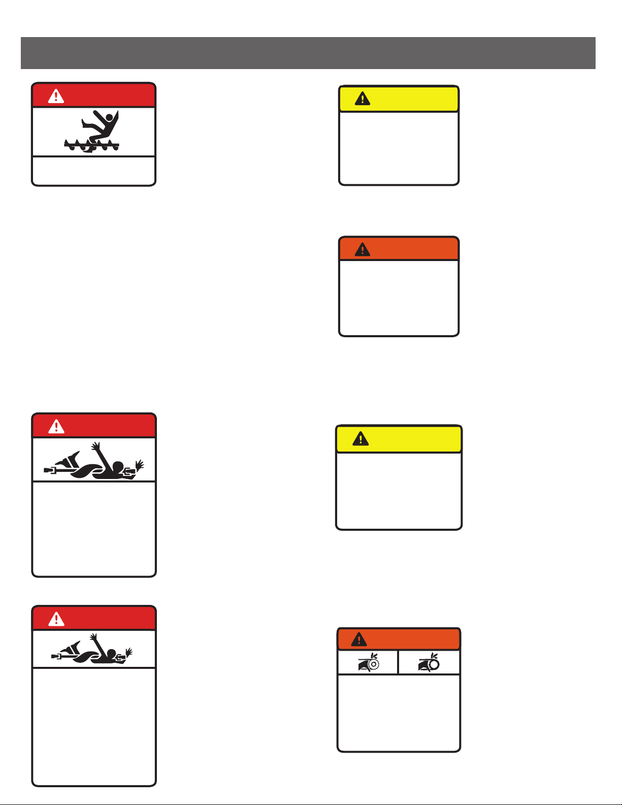
Stones or other objects
may be thrown great
distances by the auger,
especially at higher RPM.
Do not stand in front of
the blower when it is in
operation.
Any debris or stones which are swept into
the fan can be thrown at great distances.
Do not allow any bystanders to stand in
the oath of the discharge chute.
Shields are supplied for your protection.
Do not remove shield and do not operate
the machine unless all shields are in place.
Do not service, adjust or repair until the PTO
has been disengaged, the motor shut o,
the unit lowered to the ground and all parts
have stopped moving. Any moving part has
the possibility of entangling the operator or
his clothing and causing serious injury,
dismemberment or death.
Colour: Red
Location: Blower Side
Colour: Yellow
Location: Blower Back
Do not service, adjust or
repair any equipment
attached to the 3PT
hitch hydraulic, without
lowering the unit to the
ground. If work must be
performed underneath
the unit, block the unit
in a raised position.
Colour: Orange
Location: Blower Back
Do not attempt any
servicing of the blower
while the tractor engine
is running. If the tractor
PTO is accidentally
engaged the serviceman
could become entangled
in moving parts and
seriously injured or killed.
Be certain. Be safe.
Shut o the engine.
Colour: Yellow
Location: Blower Back
Every eort is made to
ensure that a well
constructed high quality
product leaves the
manufacturer. Again the
dealer inspects and
services each unit before
it leaves his lot.
Colour: Orange
Location: Blower Side
Colour: Red
Location: PTO Shaft
Never go near any moving
parts. Because tractor PTO
may be accidentally engaged,
Repair or couple PTO unless
tractor engine is shut o.
Do not remove shields.
Be sure that PTO shield turns
freely and independently of
the driveline. Do not operate
unless all shields are in place.
Be sure that PTO shaft is
attached securely at both
ends before operating.
SAFETY DECALS BE-SBSxxG
To keep your blower in
good operating condition,
please inspect and re-tighten as necessary any loose
nuts or studs after a half hour break in period.
Thereafter periodic checks will ensure that your
blower remains in top working condition.
CAUTION
Lower or block elevated components before
servicing or when leaving the machine.
Elevated components can fail and cause
serious injury.
Abaissez ou bloquez les éléments surélevés
avant de faire l’entretien lorsque vous vous
éloignez de la machine. Les éléments
surélevés peuvent tomber et causer des
blessures sérieuses.
DANGER
Shut off engine before
servicing machine.
Éteindre le moteur avant
de faire l’entrtien.
CAUTION
All nuts and bolts must be
re-tightened regularly.
Consult your Owners Manual.
Tous les écrous et les boulons
doivent être resserrés à
intervalles réguliers. Consultez
le manuel de l’usager.
DANGER
To prevent Serious Injury or Death:
• Keep hands, feet and clothing away
from auger intake
WARNING
MOVING PART HAZARD
To prevent serious injury or death from
moving parts:
• Close and secure guards and shields
before starting.
• Keep hands, feet, hair and clothing away
from moving parts.
• Disconnect and lockout power source
before adjusting or servicing.
• Do not stand or climb on machine when
operating.
DANGER
ROTATING DRIVELINE
CONTACT CAN CAUSE DEATH
KEEP AWAY!
DO NOT OPERATE WITHOUT:
• ALL DRIVELINE, TRACTOR AND
EQUIPMENT SHIELDS IN PLACE
• DRIVELINES SECURELY
ATTACHED AT BOTH ENDS
• DRIVELINE SHIELDS THAT TURN
FREELY ON DRIVELINE
DANGER
AVOID BODILY INJURY
PRÉVENTION CONTRE
LES ACCIDENTS
1. OBJECTS MAY BE THROWN GREAT
DISTANCES BY AUGER.
LES OBJETS PEUVENT ÊTRE PROJETER À
GRANDE DISTANCE DE LA VIS HÉLICOïVALE.
2. STAY CLEAR AND WATCH OUT FOR
BYSTANDERS. KEEP ALL SHIELDS IN PLACE.
GARDEZ UNE BONNE DISTANCE ENTRE VOUS
ET LES PERONNES ENVIRONNANTES.
N’ENLEVESPAS LA TÔLE PROTECTRICE.
3. BEFORE WORKING ON MACHINE DISENGAGE
POWER, SHUT OFF ENGINE AND MAKE SURE
AUGER HAS STOPPED ROTATING.
AVANT TOUTES RÉPARATIONS, ENLEVEZ LE
ASSUREZ-VOUS QUE LA VIS HÉLICOïVALE
NE TOURNE PLUS.

SET UP
1. Turn hood to point directly behind blower (PTO side).
2. Lift hood assembly o and spread a light coat of grease on outside of blower mainframe pipe.
3. Replace hood assembly.
4. Install hood turner as per instructions.
5. Grease shear assembly, auger bearings and hydraulic hood turner if installed.
6. Check oil level in gear box.
7. Check all bolts for tightness.
8. Check auger drive chain tension and alignment.
9. Grease PTO universal joints, shield retaining collars and inner tube of PTO.
OPERATION
1. When attaching the blower make certain all guards are in place.
2. Ensure that the fan and auger rotate freely before connecting PTO shaft to the tractor.
3. Use proper pins and ensure that all connections are secure.
4. Engage the PTO at low engine RPM and slowly increase speed to operate level. Operating speed will vary
with snow, weather and ground conditions.
5. Adjust the top link of the 3PT hitch to match the ground and snow conditions. Increasing the length will
cause the blower to cut deeper into compacted snow, but may also cause the blower to scrape gravel or
stones into the fan, which can be a danger to nearby persons, pets, livestock or buildings. Decreasing the
length of the top link causes the blower to ride back on the skid shoes, raising the cutting height, thereby
reducing the possibility of scraping gravel or stones into the blower.
6. Adjust the deflector for the distance of throw required. Moving the adjusting bar, to shorten the distance
between the pins increases the thrown.
7. Be aware of the presence of people and objects that may be obscured from vision by blowing or drifted snow.
Be certain that no children have tunneled into snowbanks which are to be removed. Never let children slide
down snowbank in the vicinity of an operating blower.
SERVICE
1. Before servicing or adjusting, disengage the PTO, lower the unit to the ground and shut o engine.
2. To prevent freezing of hood or other moving parts apply a solution of antifreeze or light oil.
3. Check gearbox oil level on a regular basis. If oil level is low, use a good quality 80W-90 gear oil.
Change oil after 50 hours during break-in period. Change after 700-750 hours or yearly.
4. Grease the shear assembly and hydraulic hood turner every five hours of operation.
5. Grease the auger bearings every ten hours of operation.
6. Check auger drive chain tension and alignment. Adjust if necessary.
BE-SBSxxG
INSTALLATION
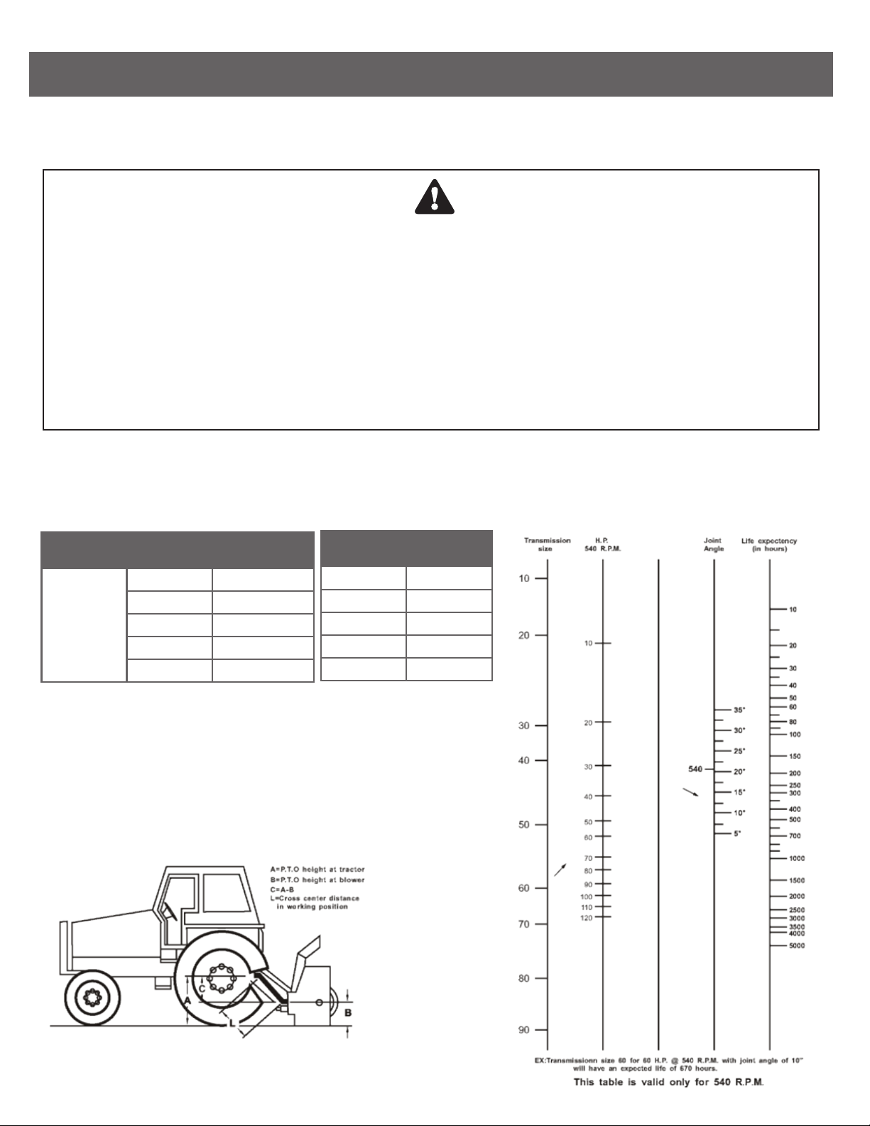
WARNING!
Unfortunately, snowblowers will be faced with forgotten or hidden objects under the snow,
such as chain, tires, stones, pieces of wood, etc.
In spite of all our eorts, machines are not built to resist all those conditions.
DANGER!
It is dangerous to use a tractor which is too big or too powerful. The tractor will always be able to
overload the blower, even if the machine is already at maximum capacity. Tractor being very high,
too large angles at PTO universal joints will result and life of universal joints will be
shortened dramatically.
A proper initial installation will give you years of satisfactory service on your equipment. Please read carefully
following instructions which have been specially made to help you and make you satisfied with your purchase.
PTO SHAFT ANGLES
PTO Shafts are made to transmit power with angles at universal joints. However, these angles should be kept
to a minimum. Larger the angle, shorter the lift of PTO. For example a snowblower sold for a tractor capacity
of 60-70 HP, which would be attached to a 60 HP Tractor, operating at maximum capacity (60 HP Continuous).
HOW TO DETERMINE PTO ANGLE
1) Lower blower on ground
2) Take measures A, B and L
3) Subtract B of A (A-B=C)
4) Divide L by C (L/C=F)
5) Compare F factor in table to find
PTO angle (interpolate, if necessary).
HP PTO ANGLES ESTIMATED
LIFE (HOURS)
450 Hours5°60 @ 540 RPM
195 Hours10°Using #50 PTO
90 Hours15°
40 Hours20°
20 Hours25°
F FACTOR
6
3.75
2.75
2.15
1.75
ANGLE
10°
15°
20°
25°
30°
BE-SBSxxG

INSTALLATION (CONT.)
Previous examples clearly demonstrate that universal joint angle is directly related with life of PTO in order to
reduce angle, it is necessary to increase the distance between snowblower and tractor.
It is impossible to increase the distance between snowblower and tractor, in order to maintain a reasonable
angle at PTO, it is recommended to use a large size of PTO, That is a greater capacity PTO, (please refer to
your dealer for more details).
For snowblowers of 100 HP an additional gearbox is also available that can be mounted on existing snowblower
gear box, which increased the input shaft height, reducing angle at PTO joints. This gear box also has a an
input speed of 1000 RPM, which greatly increases PTO capacity.
ANGLES AT EACH END OF PTO
A popular habit is to change snowblower angle in order to obtain a better scraping eect. This practice can
become harmful to the PTO, angle at each end being unequal. There will be a fan speed variation as well as a
drastic increase of load on cross and bearings. To avoid, it is recommended to keep tractor PTO Shaft and
snowblower input shaft always parallel.
SHEAR BOLTS
Shear bolts are built to break under shocks on the fan or on the auger. However, under certain circumstances,
this security is not adequate. Example: a sudden high impact shock on the fan may, in some cases, break the fan
shaft without breaking the shear bolt.
If the shear bolt breaks, make sure to always replace it with a same category bolt (grade 8.8). It is necessary to
always maintain this bolt very tight, in order to keep the eciency of the shearing mechanism.
WARNING: The gear box fan shafts are made with special allow steel. Moreover, they are case hardened
to increase capacity to shock load. These shafts cannot be broken under normal snow loads.
However, undesirable objects may enter the fan and either bend or break gear box shaft. It is understood that
gear box cannot be built to resist every possible overloads and consequently, gear box fan shafts will not be
replaced under warranty. Therefore, the user of the snowblower must be very careful.
BE-SBSxxG

SET UP INSTRUCTIONS
1. Un-crate items and compare with the parts breakdown found in the Operator’s Manual.
2. Bolt on left and right skid shoes according to Image 1.
3. Assemble the chute. Following manner of assembly in Image 2 and Image 3. Refer to the snowblower
diagram in the diagram in the operator’s manual for exploded view.
Image 1: Assembled Skid Shoe.
Image 2: Chute Assembly.
Image 4: Chute Bearing.
Note: Shims (#24 in parts list) for
bearings must be installed on the top
bottom of bearings.
The bolts must be oriented with the
threads down, see Image 4.
Image 3: Chute Assembly.
BE-SBSxxG

SET UP INSTRUCTIONS (CONT.)
Image 5: Crank Support Bracket
Image 7: A Frame Top Assembly
Note: Hand crank support bracket must be
installed on the bottom of chute flange.
Image 6: Hitch Frame
4. Assemble hitch, see Image 6.
5. Assemble the hitch top assembly and chute crank support brackets as shown in image 7.
6. Refer to page 2 of the operator’s manual for final service and installation of snowblower.
BE-SBSxxG

SNOWBLOWER DIAGRAM BE-SBSxxG

SNOWBLOWER PARTS LIST BE-SBSxxG
REF NO. PART NO. DESCRIPTION QTY
Main Frame1300011 1
Lock Nut M101300022 13
Bearing SAPF-206-20 C/W Flange1300033 1
Nut M61300044 1
Bolt M10x201300055 3
Lock Nut M121300066 17
Skid Plate1300077 2
Bolt M12x301300088 4
Bolt M16x901300099 1
Washer 1613001010 4
Bearing 6203-2RS.5/813001111 1
Idler Sprocket13001212 1
Spacer13001313 1
Lock Nut M1613001414 1
Bolt M12x4013001515 8
Bearing HCFS207-23 C/W
Cast Flange
13001616 2
Washer 1213001717 8
Lock Washer 613001818 1
Connector Link #6013001919 1
Roller Chain #60 (56-1/2”)13002020 6
Bolt M10x3013002121 1
Auger Drive Sprocket13002222 1
Auger for 50”13502323-50” 1
Auger for 60”13602323-60” 1
Auger for 72”13722323-72” 1
Turning Screw13002828 1
Bolt M6x4013002929 1
Lock Nut M613003030 1
Hand Crank13003131 1
Mounting Plate for Handle13003232 1
Auger for 76”13762323-76” 1
Fan13002424 1
Flat Washer 3/8”13002525 1
Bolt 3/8”x1-1/4”13002626 1
Lock Pin 6x4013002727 1
REF NO. PART NO. DESCRIPTION QTY
Nylon Washer13003333 1
Special Washer ø12x0.213003434 10
Bearing 6301-2RS113003535 5
Lock Nut M813003636 3
Mounting Plate for Chute13003737 1
Lock Bolt13003838 2
Bolt M12x4513003939 5
Chute (W/O Deflector)13004040 1
Bolt M8x3013004141 1
Bolt M6x3013004242 1
Adjusting Arm13004343 1
Deflector Hinge Pin13004444 1
Cotter Pin ø213004545 2
Deflector13004646 1
Lock Plate13004747 1
Mounting Bracket
for Crank Handle
13004848 1
Cross Shaft for 50”13504949-50”
49-60”
49-72”
49-76”
1
Cross Shaft for 60”136049
50
1
Cross Shaft for 72”137249
51
1
Cross Shaft for 76”137649
52
1
PTO130050
53
1
Bolt M18x130130051
54
1
Lock Nut M18130052
55
1
Bolt M10x130130053
56
4
Hitch Pin ø22x120130054
57
2
Right Tube Hitch Frame130060
63
1
Connecting Bracket130061 1
Rear Brace130062 1
Bolt M18x45130063 2
Lock Pin ø8130055
58
2
Keystock 1/4 Sq. x 1-1/2130056
59
1
Gearbox130057
60
1
A-Frame130058
61
2
Left Tube Hitch Frame130059
62
1

SHIELD ASSEMBLY
Plastic Shield Assembly #69.888.998
Complete PTO - Bondioli Type Series 4 # 69.888.400
Tractor Yoke
# 21-10-00
Shearbolt Clutch
Series 4
# 57-117-18
Shearbolt # 01.008.045
M8 x 45x1.25 (GR8.8)
Nut # 09-000.008
Nyloc M8x1.25
BE-SBSxxG

SHIELD - Excessive wear of shield
bearings.
- Insucient lubrication
- Incorrect chain mounting.
- Shield interfering with
implement.
- Follow lubrication instructions
- Mount chain to allow maximum
angularity.
- Avoid contact of the shields
with xed parts of the machine
or tractor.
- Replace shield bearings.
- Chain moving or failure. - Shield interfering with
implement
- Incorrect chain mounting.
- Avoid contact of the shields
with xed parts of the machine
or tractor.
- Mount chain to allow maximum
angularity.
- Replace defective parts.
- Guard cone damaged. - Guard cone in contact with
components on the tractor
and/or implement.
- Excessive Angularity.
- Eliminate interference between
guard cones and any part on
the tractor and/or implement.
- Avoid excessive angle during
cornering or when lifting or
lowering the implement.
- Replace damaged guard cones.
- Eliminate interference between
guard cones and any part on
the tractor and/or implement.
- Replace damaged tubes.
- Adjust guard tubes length with
longer tubes.
- Guards in contact with
components on the tractor
and/or implement.
- Guard tubes overlap too short
or no overlap at all with
extended P.T.O. Drive shaft.
- Guard tubes damaged
(deformed and split at one side).
*Note: Shield bearing must be greased every 8 working hours.
For any additional details (capacity, angle, length), please refer to catalogue.
Sold by:
AVOIDABLE DAMAGES POSSIBLE CAUSES CORRECTIVE ACTIONS
16hr 8hr 8hr
16hr 16hr
BE-SBSxxG

Cross Kit
Telescopic Tube
- Cross arms broken. - Extreme torque peak or chock
load.
- Axial Loads too high.
- Use appropriate safety device.
- Change to a larger P.T.O. size.
- Shorten P.T.O. shaft
- Replace defective cross
bearings.
- Bearing caps turning in their
cross journal.
- Overheated bearing caps.
- Telescopic tubes failure or
twisting.
- Extreme torque peak or shock
load.
- Short tube engagement.
- Use appropriate safety device.
- Change to larger P.T.O. size
- Replace the P.T.O. drive shaft
with one having adequate
length.
- Replace defective tubes.
- Change to a P.T.O. drive shaft
with one having adequate
length
- Replace the P.T.O. drive shaft
with one having adequate
length.
- Carefully follow greasing
instructions.
- Replace defective tubes.
- Extreme load when sliding.
- Short tube engagement.
- Inadequate greasing.
- Continuous (sand, etc.).
- Accelerated wear of telescopic
tubes.
- Excessive continuous torque
and/or excessive working angle.
- Inadequate greasing.
- Verify compatibility between
shaft and working conditions.
- Carefully allow greasing
instructions.
- Replace aective cross
bearings.
- Excessive continuous torque
and/or excessive working angle.
- Inadequate greasing.
- Verify compatibility between
shaft and working conditions.
- Carefully follow greasing
instructions.
- Replace defective cross
bearing.
*Note: Cross bearing must be greased every 8 working hours.
*Note: Telescopic tubes must be cleaned and greased every 16 working hours.
- Accelerated wear of cross kit.
AVOIDABLE DAMAGES POSSIBLE CAUSES CORRECTIVE ACTIONS
AVOIDABLE DAMAGES POSSIBLE CAUSES CORRECTIVE ACTIONS
BE-SBSxxG
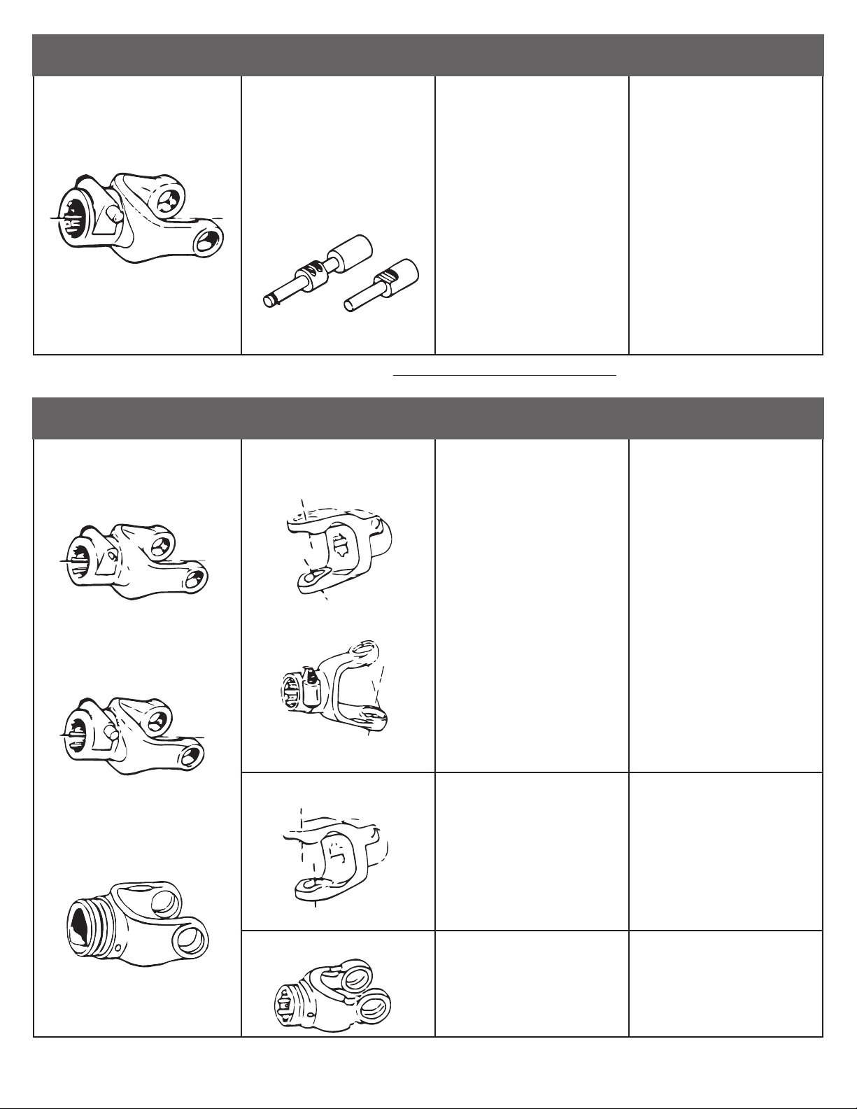
Quick-disconnect yoke
Yoke
- Quick-disconnect pin tight or
completely seized.
- Quick-disconnect pin damaged
(broken or bent).
-Quick-disconnect pin damaged
in the locking portion.
- Quick-disconnect pin dirty
(insucient maintenance).
- Quick-disconnect pin defective
(forced engagement, incorrect
handling).
- Excessive shaft length.
- Axial loads too high.
- Clean, oil and follow service
instructions.
- Replace quick-disconnect pin.
- Shorten shaft length (cut both
telescopic tubes as well as
shields and remove burrs).
- Replace quick-disconnect pin.
- Clean and grease telescopic
tubes and replace both tubes,
if necessary.
- Replace quick-disconnect pin.
- Yoke ears deformation.
- Yoke ears distorted.
- Yoke ears worn or pounded.
- Excessive shaft length.
- Axial loads too high.
- Excessive working angle and
torque.
- Overload caused by high
starting and peak torques.
- Excessive working angle.
- Shorten shaft length (cut both
telescopic tubes as well as
shields and remove burrs).
- Replace defective yokes.
- Clean and grease telescopic
tubes and replace both tubes
if necessary.
- Replace defective yokes.
- Verify compatibility between
shaft and working conditions
- Disengage tractor P.T.O. during
cornering or when lifting or
lowering the implement.
- Replace defective yokes.
- Engage P.T.O. more carefully.
- Use appropriate safety device.
- Replace defective yokes.
- Avoid excessive working angle.
- Disengage tractor P.T.O. during
cornering.
- Replace defective yokes.
*Note: Quick-disconnect pins must be cleaned and greased every 16 working hours.
AVOIDABLE DAMAGES POSSIBLE CAUSES CORRECTIVE ACTIONS
AVOIDABLE DAMAGES POSSIBLE CAUSES CORRECTIVE ACTIONS
BE-SBSxxG

This manual suits for next models
5
Table of contents


