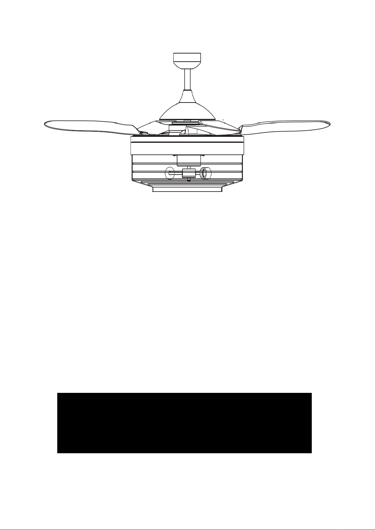
Fanaway Montclair Installation Instructions
2 | P a g e
THANK YOU FOR PURCHASING
Thank you for purchasing this quality Fanaway product. To ensure correct function and safety, please read
and follow all instructions carefully before assembly, installation and use of this ceiling fan. Please keep
instructions for future reference.
SAFETY PRECAUTIONS
1. This appliance can be used by children aged from 8 years and above and persons with reduced physical,
sensory or mental capabilities or lack of experience and knowledge if they have been given supervision
or instruction concerning the use of the appliance in a safe way and understand the hazards involved.
Cleaning and maintenance shall not be undertaken by children without supervision.
2. Children should be supervised to ensure that they do not play with the appliance.
3. An all-pole disconnection switch must be incorporated into the fixed wiring, in accordance with local wiring
rules.
4. Do not dispose of electrical appliances as unsorted municipal waste, use separate collection facilities.
Contact your local government for information regarding the collection systems available. If electrical
appliances are disposed of in landfills or dumps, hazardous substances can leak into the ground water
and get into the food chain, damaging your health and well-being.
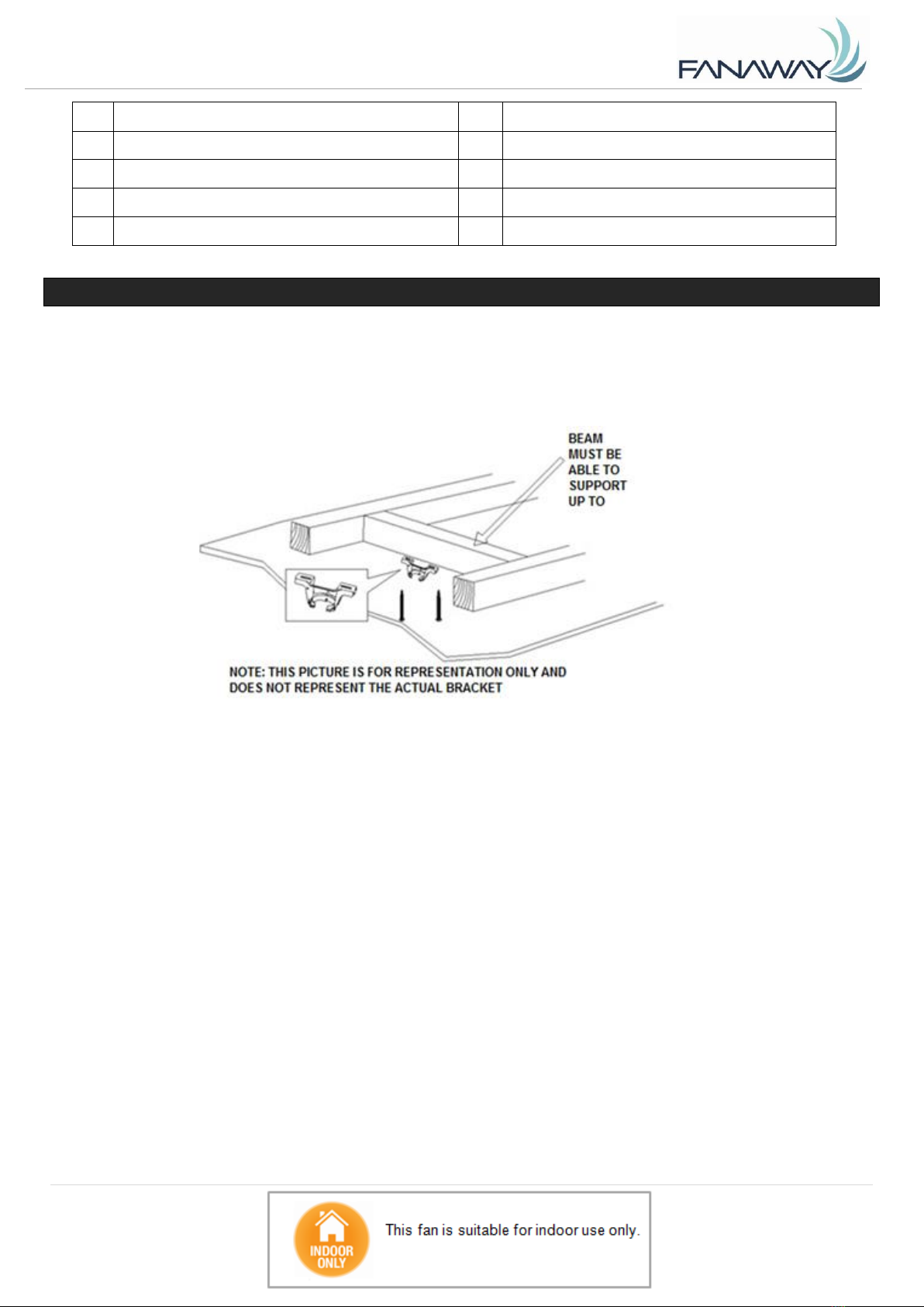
5. The structure to which the fan is to be mounted must be capable of supporting a weight of 48kg.
6. The fan should be mounted so that the blades are at least 2.3 m above the floor
7. This fan is suitable for indoor use only. Mounting the fan in a location where it is subject to water or
moisture is dangerous and may increase the risk of damage, injury or electrical shock and will void the
warranty.
8. Electrical installation should be performed by a qualified licensed electrician.
9. WARNING: If unusual wobbling or oscillating movement is observed, immediately stop using the ceiling
fan and contact the manufacturer, its service agent or suitably qualified persons.
10. The replacement of parts of the safety suspension system device shall be performed by the manufacturer,
its service agent or suitably qualified persons.
11. The fixing means for attachment to the ceiling such as hooks or other devices shall be fixed with a
sufficient strength to withstand 4 times the weight of the ceiling fan; that the mounting of the suspension
system shall be performed by the manufacturer, its service agent or suitably qualified persons.