10
/01/07
10
/
10
/
07
OPERATION
INSTRUCTIONS-BABLT
o Consult
ANSI
MH29.
1,
Section
12
for
the owner's I user's responsibilities regarding the operation, care, and
maintenance
of
this machine.
0
Ensure
that
all
employees involved in the operation
of
this
unit
understand and
follow
these instructions!
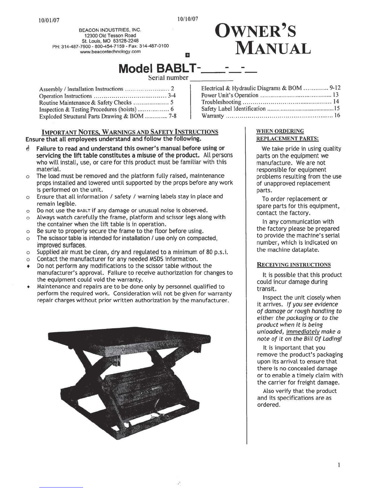
The standard model
sAsLT
is suitable
for
use
indoors
in
most non-classified industrial locations.
It
is intended
to
be
used
to
raise and lower stable, evenly-distributed, non-hazardous materials loads
and/or
containers (with rigid
sides
having a size
or
footprint approximately
the
same
size
as
the platform).
Loading:
The load rating, in pounds, is shown
on
the
machine dataplate located
on
the front side
lip
of
the
platform.
It
indicates the net capacity
of
the
scissor table
with
a static load
that
is centered and evenly distributed
on
the
platform.
Warning: The airbag table's rollers are not captured. Therefore, do
not
overhang any load
at
the
hinged end
of
the
platform -that could
cause
the
roller
end
of
the
platform
to
tip
up and dump the load. For applications involving side
or
end edge loading, consult
the
factory.
Note: The addition
of
any ancillary equipment
to
the
airbag scissor
lift
table by third parties must be taken into
account when determining the maximum working load
to
be placed
on
the
unit.
Warning:
Do
not
exceed the
BABLT's
load ratings. Injury
to
personnel
or
permanent damage
to
the
unit could result
from exceeding
the
listed capacity.
Operation:
Inspect
the
perimeter pinch point guards' operation daily.
Warning:
Keep
all
personnel clear
of
the
machine when
it
is in operation.
Be
certain no part
of
any person or object is
under any part
of
the platform before lowering
the
unit.
Caution: Always carefully watch
the
unit and any load
on
it
when
it
is in operation.
The
ABLT
is furnished with either a constant-pressure (dead-man style) pushbutton (standard) or
twin
foot pedal
(optional) control.
Pressing
the
"UP" pushbutton (or
foot
pedal)
will
open
the
valves
to
supply pressure
to
the airbag(s)
to
raise
the
platform. The platform
will
raise only while
the
control is pressed.
Upon
releasing
the
control, the platform
will
stop
and hold its position.
Pressing
the "D
OWN"
pushbutton (or foot pedal)
will
actuate the lowering valve
to
allow the platform
to
descend by
gravity. Again, releasing
the
control
will
stop the platform movement, and
the
unit
will
hold
its
position.
Note:
Due
to
the compressibility
of
air, adding or removing a load (or
part
of
a load) from the platform while
in
a
raised position
will
cause
the platform
to
position
to
change (raise or lower).
When
lowering the platform,
if
an
obstruction is encountered which activates
the
platform perimeter pinch point
(toe) guards, the
platfor
m
will
raise
until
the obstruction is cleared or
until
the
platform reaches is upper travel
limit.
Caution: Never
use
the
airbag table
if
any damage or unusual noise is observed,
ifit
is
in
need
of
repairs, or
ifit
seems
to
be malfunctioning. Notify your supervisor or maintenance personnel
if
you notice anything out
of
the ordinary.
Ensure
that
all
information/safety/warning labels stay
in
place
and
are legible. Refer
to
the labels
page
in
this
manual.
3