BeagleBone RS232 Cape User manual

BeagleBone RS232 Cape
System Reference Manual
Revision A1
August 10th, 2012

BeagleBone
RS232
Cape
System Reference Manual
Revision A
Page 2 of 22
THIS DOCUMENT
This work is licensed under the Creative Commons Attribution-Share Alike 3.0 Unported
License. To view a copy of this license, visit http://creativecommons.org/licenses/by-
sa/3.0/ or send a letter to Creative Commons, 171 Second Street, Suite 300, San
Francisco, California, 94105, USA.
All derivative works are to be attributed to BeagleBoardtoys.com.
For more information, see http://creativecommons.org/license/results-
one?license_code=by-sa
For any questions, concerns, or issues submit them to support@beagleboardtoys.com
BEAGLEBONE RS232 CAPE DESIGN
These design materials referred to in this document are
*NOT SUPPORTED* and DO NOT constitute a
reference design. Only “community” support is allowed via
resources at Beagleboardtoys.com/support
THERE IS NO WARRANTY FOR THE DESIGN
MATERIALS, TO THE EXTENT PERMITTED BY
APPLICABLE LAW. EXCEPT WHEN OTHERWISE
STATED IN WRITING THE COPYRIGHT HOLDERS
AND/OR OTHER PARTIES PROVIDE THE DESIGN
MATERIALS “AS IS” WITHOUT WARRANTY OF
ANY KIND, EITHER EXPRESSED OR IMPLIED,
INCLUDING, BUT NOT LIMITED TO, THE IMPLIED
WARRANTIES OF MERCHANTABILITY AND
FITNESS FOR A PARTICULAR PURPOSE. THE

BeagleBone
RS232
Cape
System Reference Manual
Revision A
Page 3 of 22
ENTIRE RISK AS TO THE QUALITY AND
PERFORMANCE OF THE DESIGN MATERIALS IS
WITH YOU. SHOULD THE DESIGN MATERIALS
PROVE DEFECTIVE, YOU ASSUME THE COST OF
ALL NECESSARY SERVICING, REPAIR OR
CORRECTION.
We mean it; these design materials may be totally
unsuitable for any purposes.

BeagleBone
RS232
Cape
System Reference Manual
Revision A
Page 4 of 22
BeagleBoardToys provides the enclosed product(s) under the following conditions:
This evaluation board/kit is intended for use for ENGINEERING DEVELOPMENT, DEMONSTRATION, OR
EVALUATION PURPOSES ONLY and is not considered by BeagleBoardtoys.com to be a finished end-
product fit for general consumer use. Persons handling the product(s) must have electronics training and
observe good engineering practice standards. As such, the goods being provided are not intended to be
complete in terms of required design-, marketing-, and/or manufacturing-related protective considerations,
including product safety and environmental measures typically found in end products that incorporate such
semiconductor components or circuit boards. This evaluation board/kit does not fall within the scope of the
European Union directives regarding electromagnetic compatibility, restricted substances (RoHS), recycling
(WEEE), FCC, CE or UL, and therefore may not meet the technical requirements of these directives or other
related directives.
Should this evaluation board/kit not meet the specifications indicated in the User’s Guide, the board/kit may
be returned within 30 days from the date of delivery for a full refund. THE FOREGOING WARRANTY IS
THE EXCLUSIVE WARRANTY MADE BY SELLER TO BUYER AND IS IN LIEU OF ALL OTHER
WARRANTIES, EXPRESSED, IMPLIED, OR STATUTORY, INCLUDING ANY WARRANTY OF
MERCHANTABILITY OR FITNESS FOR ANY PARTICULAR PURPOSE.
The user assumes all responsibility and liability for proper and safe handling of the goods. Further, the user
indemnifies BeagleBoardtoys.com from all claims arising from the handling or use of the goods. Due to the
open construction of the product, it is the user’s responsibility to take any and all appropriate precautions
with regard to electrostatic discharge.
EXCEPT TO THE EXTENT OF THE INDEMNITY SET FORTH ABOVE, NEITHER PARTY SHALL BE
LIABLE TO THE OTHER FOR ANY INDIRECT, SPECIAL, INCIDENTAL, OR CONSEQUENTIAL
DAMAGES.
BeagleBoardtoys.com currently deals with a variety of customers for products, and therefore our
arrangement with the user is not exclusive. BeagleBoardtoys.com assumes no liability for applications
assistance, customer product design, software performance, or infringement of patents or services
described herein.
Please read the User’s Guide and, specifically, the Warnings and Restrictions notice in the User’s Guide
prior to handling the product. This notice contains important safety information about temperatures and
voltages. For additional information on BeagleBoardtoys.com environmental and/or safety programs, please
contact visit BeagleBoardtoys.com.
No license is granted under any patent right or other intellectual property right of BeagleBoard.org covering
or relating to any machine, process, or combination in which such BeagleBoardtoys.com products or
services might be or are used.
Mailing Address:
Beagleboardtoys.com
1380 Presidential Dr. #100
Richardson, TX 75081
U.S.A.

BeagleBone
RS232
Cape
System Reference Manual
Revision A
Page 5 of 22
WARRANTY: The BeagleBone RS232 Cape is warranted against defects in materials and
workmanship for a period of 90 days from purchase. This warranty does not cover any problems
occurring as a result of improper use, modifications, exposure to water, excessive voltages, abuse,
or accidents. All boards will be returned via standard mail if an issue is found. If no issue is found
or express return is needed, the customer will pay all shipping costs.
Before returning the board, please visit Beagleboardtoys.com/support
To return a defective board, please request an RMA at
http://www.beagleboardtoys.com/support/rma

BeagleBone
RS232
Cape
System Reference Manual
Revision A
Page 6 of 22
Table of Contents
FIGURES...................................................................................................................................................... 7
TABLES........................................................................................................................................................ 7
1.0
INTRODUCTION............................................................................................................................... 9
2.0
CHANGE HISTORY.........................................................................................................................10
2.1
CHANGE HISTORY............................................................................................................................10
3.0
BEAGLEBONE RS232 CAPE OVERVIEW..................................................................................11
3.1
DESCRIPTIONS..................................................................................................................................11
3.2
IN THE BOX .....................................................................................................................................12
3.3
GETTING STARTED...........................................................................................................................12
3.4
REPAIRS...........................................................................................................................................13
4.0
FEATURES AND SPECIFICATIONS............................................................................................14
4.1
KEY COMPONENT LOCATIONS .........................................................................................................15
4.2
RS232 INTERFACE ...........................................................................................................................15
4.3
UART SELECTION ...........................................................................................................................16
4.4
POWER INDICATOR ..........................................................................................................................16
4.5
MECHANICAL SPECIFICATIONS ........................................................................................................16
4.6
ELECTRICAL SPECIFICATIONS ..........................................................................................................16
5.0
SYSTEM ARCHITECTURE AND DESIGN..................................................................................17
5.1
SYSTEM BLOCK DIAGRAM...............................................................................................................17
5.2
RS232..............................................................................................................................................17
5.3
UART..............................................................................................................................................18
5.4
UART TO RS232.............................................................................................................................18
5.5
EEPROM ........................................................................................................................................19
5.5.1
EEPROM Address .................................................................................................................20
5.5.2
I2C Bus..................................................................................................................................20
6.0
MECHANICAL INFORMATION...................................................................................................21
7.0
DESIGN MATERIALS.....................................................................................................................22

BeagleBone
RS232
Cape
System Reference Manual
Revision A
Page 7 of 22
Figures
Figure 1. The BeagleBone RS232 Cape....................................................................... 11
Figure 2. Key Components........................................................................................... 15
Figure 3. BeagleBone RS232 Cape High Level Block Diagram................................. 17
Figure 4. BeagleBone RS232 Cape UART Selection.................................................. 18
Figure 5. UART to RS232............................................................................................ 19
Figure 6. BeagleBone RS232 Cape EEPROM............................................................. 20
Figure 7. BeagleBone RS232 Cape Dimensions Drawing........................................... 21
Tables
Table 1. Change History............................................................................................. 10
Table 2. BeagleBone RS232 Cape Features ............................................................... 14

BeagleBone
RS232
Cape
System Reference Manual
Revision A
Page 8 of 22
NOTES

BeagleBone
RS232
Cape
System Reference Manual
Revision A
Page 9 of 22
1.0 Introduction
This document is the System Reference Manual for the BeagleBone RS232 Cape, an add-
on board for the BeagleBone.
This document is intended as a guide to assist anyone purchasing or who are considering
purchasing the board to understand the overall design and usage of the BeagleBone
RS232 Cape from the system level perspective.
The design is subject to change without notice as we will work to keep improving the
design as the product matures.
The key sections in this document are:
Section 2.0 – Change History
Provides tracking for the changes made to the System Reference Manual.
Section 3.0 – Overview
This is a high level overview of the BeagleBone RS232 Cape.
Section 4.0 – Features and Specification
Provided here are the features and electrical specifications of the board.
Section 5.0 – System Architecture and Design
This section provides information on the overall architecture and design of the
BeagleBone RS232 Cape. This is a very detailed section that goes into the design
of each circuit on the board.
Section 6.0 – Mechanical
Information is provided here on the dimensions of the BeagleBone RS232 Cape.
Section 7.0 – Design Materials
This section provides information on where to get the design files.

BeagleBone
RS232
Cape
System Reference Manual
Revision A
Page 10 of 22
2.0 Change History
2.1 Change History
Table 1 tracks the changes made for each revision of this document.
Table 1. Change History
Rev
Changes Date
By
A1 Initial release. 08/10/2012 BBT
.
BeagleBone
RS232
Cape
System Reference Manual
Revision A
Page 11 of 22
3.0 BeagleBone RS232 Cape Overview
3.1 Descriptions
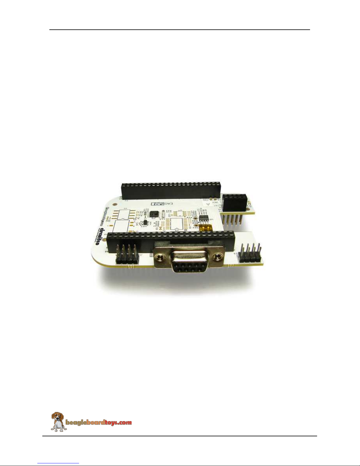
The BeagleBone RS232 Cape provides an RS232 interface to the BeagleBone via a
standard D-Sub 9 female serial connector. This connector is located to the side so it
doesn't interfere with any capes stacked above it. By default, the BeagleBone RS232
Cape uses UART2 port on the AM335x for RS232 connection; however, users will have
the freedom to choose among UART1, UART2, UART4, and UART5 ports.
Figure 1 below is a picture of the board.
Figure 1. The BeagleBone RS232 Cape

BeagleBone
RS232
Cape
System Reference Manual
Revision A
Page 12 of 22
3.2 In The Box
The final packaged BeagleBone RS232 Cape Rev A1 product will contain the following
items: -1 BeagleBone RS232 Cape
-1 Wiki information card
3.3 Getting Started
Following the instructions below to start using your BeagleBone RS232 Cape:
1) Mount the BeagleBone RS232 on top of BeagleBone
2) Make sure the micro SD card using with BeagleBone has latest Angstrom image.
3) Connect the BeagleBone RS232 Cape to the computer using a RS232-compatible
serial cable. Remember the port number of this connection.
Note: In Windows, the serial port number can be viewed under “Ports (COM &
LPT)” section inside “Device Manager”. To open the “Device Manager”
windows, right-click “My Computer”, choose “Properties”, select the
“Hardware” tab, and click “Device Manager”.
4) Connect the BeagleBone to the computer using a USB cable. Remember the port
number of this connection. This will also power up the BeagleBone.
5) Open a terminal application (Teraterm, Hyperterminal, etc) and open new
connection with following settings: baud rate - 115200, data – 8 bit, parity – none,
stop – 1 bit, flow control – none. Select the port corresponding to the RS232
connection.
6) Open a second instance of the terminal application and connect to the USB serial
connection using the same settings as above.
7) Hit the reset switch S1 on the BeagleBone. The BeagleBone is now rebooting
inside the USB serial terminal window.
8) Press “Enter” to stop the booting process at UBoot. If missed, hit the reset switch
again and press “Enter” before the UBoot count down stops at zero.
9) At UBoot, run the following commands to temporarily use the RS232 connection:
setenv console ttyO2,115200n8
boot
10)BeagleBone will continue the booting process; however, the kernel messages will
not show up inside the RS232 terminal window. You can now start using the
RS232 connection via UART2.
Note: This RS232 connection is temporary. To permanently use the RS232
connection, you need to change the environment variables of UBoot.

BeagleBone
RS232
Cape
System Reference Manual
Revision A
Page 13 of 22
3.4 Repairs
If you feel the board is in need of repair, follow the RMA Request process found at
http://www.beagleboardtoys.com/support/rma
Do not send the board in for repair until an RMA
authorization has been provided.
Do not return the board to the distributor unless you want to get a refund. You must get
authorization from the distributor before returning the board.
BeagleBone
RS232
Cape
System Reference Manual
Revision A
Page 14 of 22
4.0 Features and Specifications
This section covers the specifications of the BeagleBone RS232 Cape and provides a
high level description of the major components and interfaces that make up the board.
Table 2 provides a list of the BeagleBone RS232 Cape’s features.
Table 2. BeagleBone RS232 Cape Features
Compatible
Serial Port
UART1
UART2 (default)
UART4
UART5
Power 3.3 V via expansion header
Indicator Power LED
Connector Two 46-position connectors
One 10-position connector
One D-Sub9 serial connector
BeagleBone
RS232
Cape
System Reference Manual
Revision A
Page 15 of 22
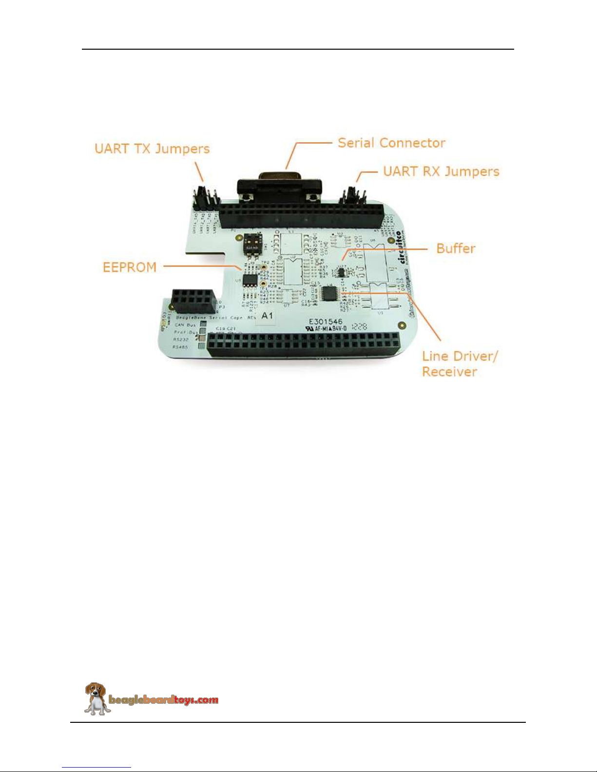
4.1 Key Component Locations
Figure 2 shows the location of the key components on the board.
Figure 2. Key Components
4.2 RS232 Interface
The BeagleBone RS232 Cape uses the SN65C322EPW to provide an RS232 serial
interface for BeagleBone. SN65C322EPW features one line driver and one line receiver
to translate data from RS232 level to UART level and vice versa. The RS232 signals are
connected to TX and RX pins of D-Sub9 serial connector on the board. The UART
signals are connected to four different UART ports on the BeagleBone via selection
jumpers.

BeagleBone
RS232
Cape
System Reference Manual
Revision A
Page 16 of 22
4.3 UART Selection
The BeagleBone RS232 Cape provides an option for users to choose among four UART
ports from AM335x (UART1, 2, 4, and 5). The TXD and RXD signals are connected to
the corresponding signal of each UART via jumper headers. The default selection is
UART2. If one wishes to use a UART port, ensure the jumper for that port is installed.
4.4 Power Indicator
The BeagleBone RS232 Cape features an LED (D3) to indicate that power is applied to
the cape. This LED is green when lit.
4.5 Mechanical Specifications
Size: 4.00” x 2.50”
Layers: 4
PCB thickness: .062”
RoHS Compliant: Yes
4.6 Electrical Specifications
Table 3 is the electrical specification of the external interfaces to the BeagleBone RS232
panel.
Table 3. BeagleBone RS232 Electrical Specifications
Specification Min Typ Max Unit
Power
Input Voltage DC 3.3 V
Environmental
Temperature range 0 +85 C

BeagleBone
RS232
Cape
System Reference Manual
Revision A
Page 17 of 22
5.0 System Architecture and Design
This section provides a high level description of the design of the BeagleBone RS232
Cape and its overall architecture.
5.1 System Block Diagram
Figure 3 is the high level block diagram of the BeagleBone RS232 Cape.
Figure 3. BeagleBone RS232 Cape High Level Block Diagram
5.2 RS232
The BeagleBone RS232 Cape uses a D-Sub 9 female serial connector to provide RS232
connection. The TX, RX, and GND signals of RS232 interface are connected to pin 2, 3,
and 5 of D-Sub connector J1. A compatible serial cable is required to communicate via
RS232 interface. RS232 data are transmitted or received by SN65C322EPW, which
translate data between UART and RS232.

BeagleBone
RS232
Cape
System Reference Manual
Revision A
Page 18 of 22
5.3 UART
There are four UART ports available on the expansion header of BeagleBone; each of
these ports can be used by the RS232 Cape. The TXD and RXD signals of
SN65C322EPW can be connected to the corresponding signals of UART1, 2, 4, and 5 by
installing jumpers for that signal. The default connection is UART2. This UART port is
also supported by software. If user wishes to use a different UART port, the TX and RX
jumpers for that port are required to be installed. User will also need to rebuild the kernel
to support that UART port in software.
A buffer is used to ensure the UART signals do not conflict with BeagleBone’s booting
process. Figure 4 shows the UART selection circuit on the RS232 Cape.
Figure 4. BeagleBone RS232 Cape UART Selection
5.4 UART to RS232
The BeagleBone RS232 Cape features an SN65C322EPW to translate data from RS232
level to UART level. SN65C322EPW is a single-channel line driver and receiver that can
operate from 3.3V to 5V. RX signal of RS232 interface from the D-Sub 9 serial

BeagleBone
RS232
Cape
System Reference Manual
Revision A
Page 19 of 22
connector J1 is received by the SN65C322EPW and transmitted as UART data.
Similarly, UART data from BeagleBone is translated to RS232 before transmitted to the
D-Sub 9 connector. The data signaling rate can go up to 1 Mbps.
On the BeagleBone RS232 Cape, enable signal (EN) is pulled low and FORCEOFF is
high to enable the data translation between RS232 and UART.
Figure 5 shows SN65C322EPW in RS232 schematic.
Figure 5. UART to RS232
5.5 EEPROM
The BeagleBone RS232 Cape has an EEPROM containing information that will allow the
SW to identify the board and to configure the expansion headers pins as needed.
EEPROMs are required for all Capes sold in order for them to operate correctly when
plugged in the BeagleBone.
The EEPROM used on this cape is the same one as is used on the BeagleBone, a
CAT24C256. The CAT24C256 is a 256 kb Serial CMOS EEPROM, internally organized
as 32,768 words of 8 bits each. It features a 64-byte page write buffer and supports the
Standard (100 kHz), Fast (400 kHz) and Fast-Plus (1 MHz) I2C protocol. Figure 6 is the
design of the EEPROM circuit.

BeagleBone
RS232
Cape
System Reference Manual
Revision A
Page 20 of 22
Figure 6. BeagleBone RS232 Cape EEPROM
5.5.1 EEPROM Address
In order for each Cape to have a unique address, a board ID scheme is used that sets the
address to be different depending on the order in which it is stacked onto the main board.
A two position dipswitch or jumpers is used to set the address pins of the EEPROM. It is
the responsibility of user to set the proper address for each board. Address line A2 is
always tied high. This sets the allowable address range for the expansion cards to 0x54 to
0x57.All other I2C addresses can be used by the user in the design of their Capes. But,
these addresses must not be used other than for the board EEPROM information.
5.5.2 I2C Bus
The EEPROMs on each expansion board is connected to I2C2. For this reason I2C2 must
always be left connected and should not be changed by SW to remove it from the
expansion header pin mux. The I2C signals require pull-up resistors. Each board must
have a 5.6K resistor on these signals. With four resistors this will be an affective
resistance of 1.4K if all Capes were installed.
Table of contents
Other BeagleBone Motherboard manuals


