BecherAir Components BECMATIC 550 User manual
87 West Main Street
Sodus, NY 14551
(315) 483-6923 TEL
(315) 483-6656 FAX
LAST UPDATED: 07 MAY 2015
BECMATIC MODELS 550/600/602/652
OWNER’S MANUAL – BECMATIC SPRING FEEDERS
Spring No.
Revision
MODEL
ID #
SERIAL #
FEED RATE
DATE

2
INDEX
Warranty …………………………………………………………………………….Page 3
Return Information ………………………………………………………………….Page 3
Setup ………………………………………………………………………………...Page 4
Installation of Feed Tube(s) …………………………………………………………Page 4
Mounting …………………………………………………………………………….Page 5
Operation …………………………………………………………………………...Page 10
Optional Equipment ………………………………………………………………...Page 11
Troubleshooting ………………………………………………………………….…Page 13
Preventative Maintenance…………………………………………………………...Page 14
Parts List ……………………………………………………………………………Page 16
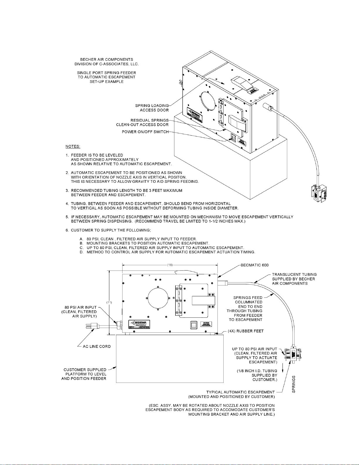
Set-up Example ……………………………………………………………………..Page 17

3
WARRANTY
STANDARD WARRANTY
The seller warrants equipment of its manufacture against defects in workmanship and material
for a period of 12 months from date of shipment from the factory.
This unit has been tooled specifically for your application. Air velocity and volume are preset at
the factory and the case has been sealed to maintain proper airflow. Disassembly or
modifications to this unit may impair operation and/or void warranty.
RETURN INFORMATION
*Call Factory for return authorization.
*Carefully pack unit to avoid damage in shipment. Insure for full value of the unit.
*Include detailed description of problem, name and phone number of the contact person, a
quantity of springs for test operations, and shipping instructions.

4
SETUP & INSTALLATION
SETUP
All models of Becmatic Spring Feeders require a 115 volt grounded electrical outlet and 80 p.s.i.
of clean air. The unit may be plugged into any standard 115 volt outlet, or may be wired directly
to any controller with 115 volt output. In installations where the air supply exceeds 80 p.s.i., a
regulator should be provided.
The feeder should be mounted above the spring escapement to allow gravity feed of the springs
through the feed tube. Feed tube length should be kept as short as possible to eliminate
excess backpressure, (36” maximum).
INSTALLATION OF FEED TUBE(S)
The feed tube is inserted into the outlet nozzle on the front of the feeder. The lock collar should
be adjusted to provide a secure grasp on the feed tube. Over tightening the lock collar will result
in damage to the nozzle and may impair the travel of the springs. Feed tube length should be
enough to allow a transition without kinks or sharp bends that will impede flow.
*230 volt models are not supplied with a plug.
*See mounting instructions.

5
MOUNTING & SPECIFICATIONS
MODEL 550
US Std. Inches
Metric (mm)
Spring O.D.
.040 - .125
1.0 –3.2 mm
Spring Length
.625
16 mm
Capacity (Vol)
.5 qt.
.5 ltr.
Electrical
115 VAC, 1.5A
230VAC, 1A
Air
80 p.s.i.
5.6 kg/cc2
Air Supply
.250 min.
6 mm min.
CLEAN AIR
110V. AC
80-P.S.I.
80 LBS P.S.I.
CLEAN AIR
115VAC 60HZ
GROUNDED
POWER
SUPPLY
(230VAC
OPTIONAL)
ESCAPEMENTS
SPRING
TO
DIVISION OF C-ASSOCIATES, LLC.
MODEL NO.
SERIAL NO.
WWW.BECHERAIR.COM
SODUS, NY 315-483-6923

6
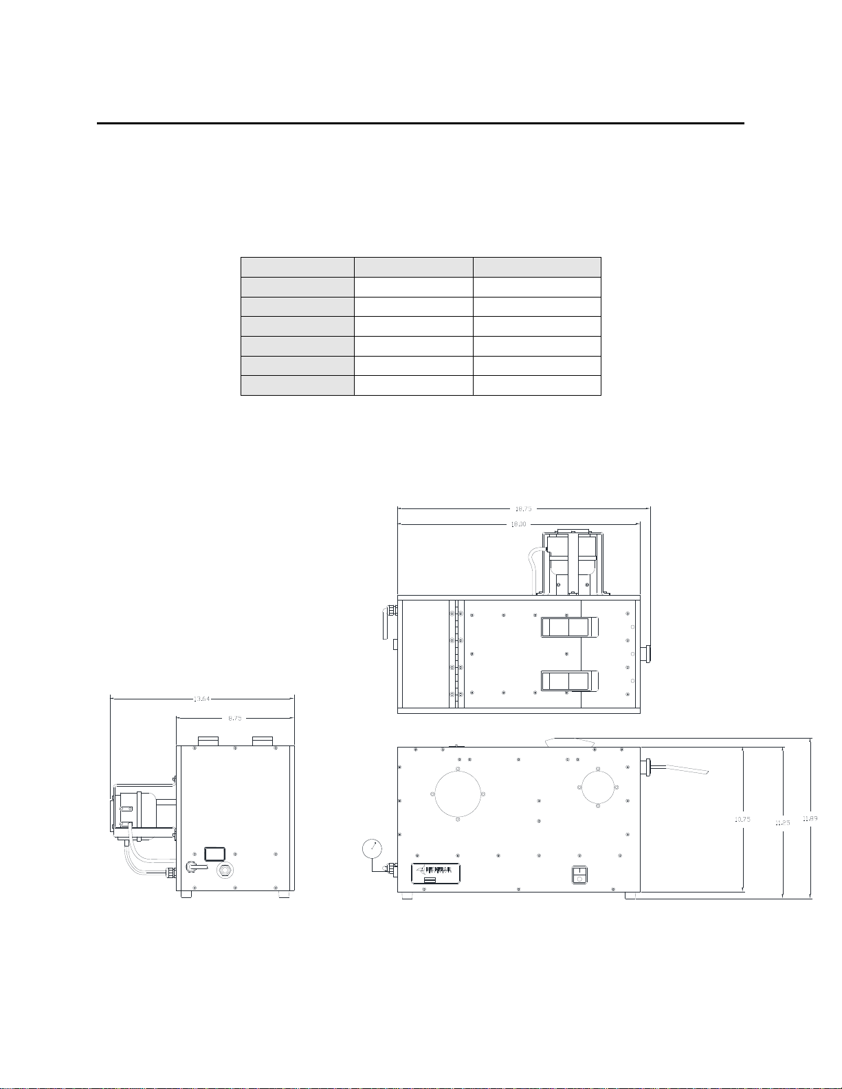
MOUNTING & SPECIFICATIONS
MODEL 600
US Std. Inches
Metric (mm)
Spring O.D.
.125 - .312
3.2 –8 mm
Spring Length
1.250
31.8 mm
Capacity (Vol)
1.5 qt.
1.4 ltr.
Electrical
115 VAC, 1.5A
230VAC, 1A
Air
80 p.s.i.
5.6 kg/cc2
Air Supply
.375 min.
10 mm min.
CLEAN AIR
110V. AC
80-P.S.I.
6.75
16.00
9.75
18.00
OPTIONAL)
115VAC 60HZ
GROUNDED
POWER
SUPPLY
(230VAC
CLEAN AIR
80 LBS P.S.I.
ESCAPEMENTS
SPRING
TO
DIVISION OF C-ASSOCIATES, LLC.
MODEL NO.
SERIAL NO.
WWW.BECHERAIR.COM
SODUS, NY 315-483-6923
~11.00

7
MOUNTING & SPECIFICATIONS
MODEL 602
US Std. Inches
Metric (mm)
Spring O.D.
.125 - .312
3.2 –8 mm
Spring Length
1.250
31.8 mm
Capacity (Vol)
1.5 qt.
1.4 ltr.
Electrical
115 VAC, 1.5A
230VAC, 1A
Air
80 p.s.i.
5.6 kg/cc2
Air Supply
.375 min.
10 mm min.
CLEAN AIR
110V. AC
80-P.S.I.
6.75
16.00
9.75
~11.00
~18.00
MODEL 602 ONLY
80 LBS P.S.I.
CLEAN AIR
115VAC 60HZ
GROUNDED
POWER
SUPPLY
(230VAC
OPTIONAL)
ESCAPEMENTS
TO
SPRING
11.64
DIVISION OF C-ASSOCIATES, LLC.
MODEL NO.
SERIAL NO.
WWW.BECHERAIR.COM
SODUS, NY 315-483-6923
8
MOUNTING & SPECIFICATIONS
MODEL 652
US Std. Inches
Metric (mm)
Spring O.D.
.250 - .625
6.35 –15.88 mm
Spring Length
1.500
38.1 mm
Capacity (Vol)
3 qt.
2.8 ltr.
Electrical
115 VAC, 1.5A
230VAC, 1A
Air
80 p.s.i.
5.6 kg/cc2
Air Supply
.375 min.
10 mm min.
110V. AC
CLEAN AIR
90-P.S.I.
ESCAPEMENTS
TO
SPRING
(230VAC
OPTIONAL)
115VAC 60HZ
SUPPLY
POWER
GROUNDED
90 LBS P.S.I.
CLEAN AIR
DIVISION OF C-ASSOCIATES, LLC.
MODEL NO.
SERIAL NO.
WWW.BECHERAIR.COM
SODUS, NY 315-483-6923
9
MOUNTING & SPECIFICATIONS
AUTOMATIC ESCAPEMENT
10
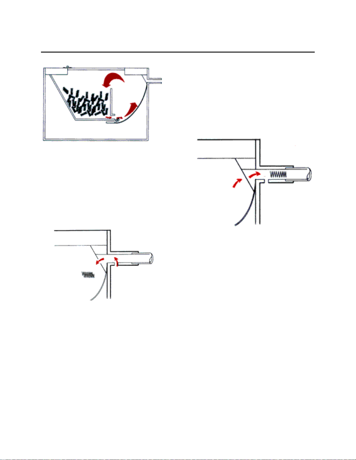
OPERATION
The Becmatic Spring Feeder/ Detangler
takes a quantity of springs from the rear
chamber and feeds them forward to the
spinning chamber where they are
separated, (See Fig.1.) and fed to the
Figure 1
outlet nozzle, (Fig. 2). A cycle timer
provides an air jet to clear the nozzle of
tangled springs (Fig.3). The springs are
then fed down the feed tube to the spring
escapement.
Figure 2
Load springs into the rear chamber of the
spring feeder/detangler. It is
recommended that the quantity be kept to
no more than is necessary to prevent
excessive spinning of springs, which may
result in hooked or damaged parts.
Figure 3
* Severely tangled or hooked springs should be removed from the reservoir prior to adding
new parts.
* Springs should be stored in closed containers to avoid contamination and damage.
* Springs should be clean, dry and free of lubricants or any foreign contamination.
* Foreign debris and damaged parts may cause jamming or impair feed rates.
* Power to the machine should be shut off when the feeder is not in use.
11
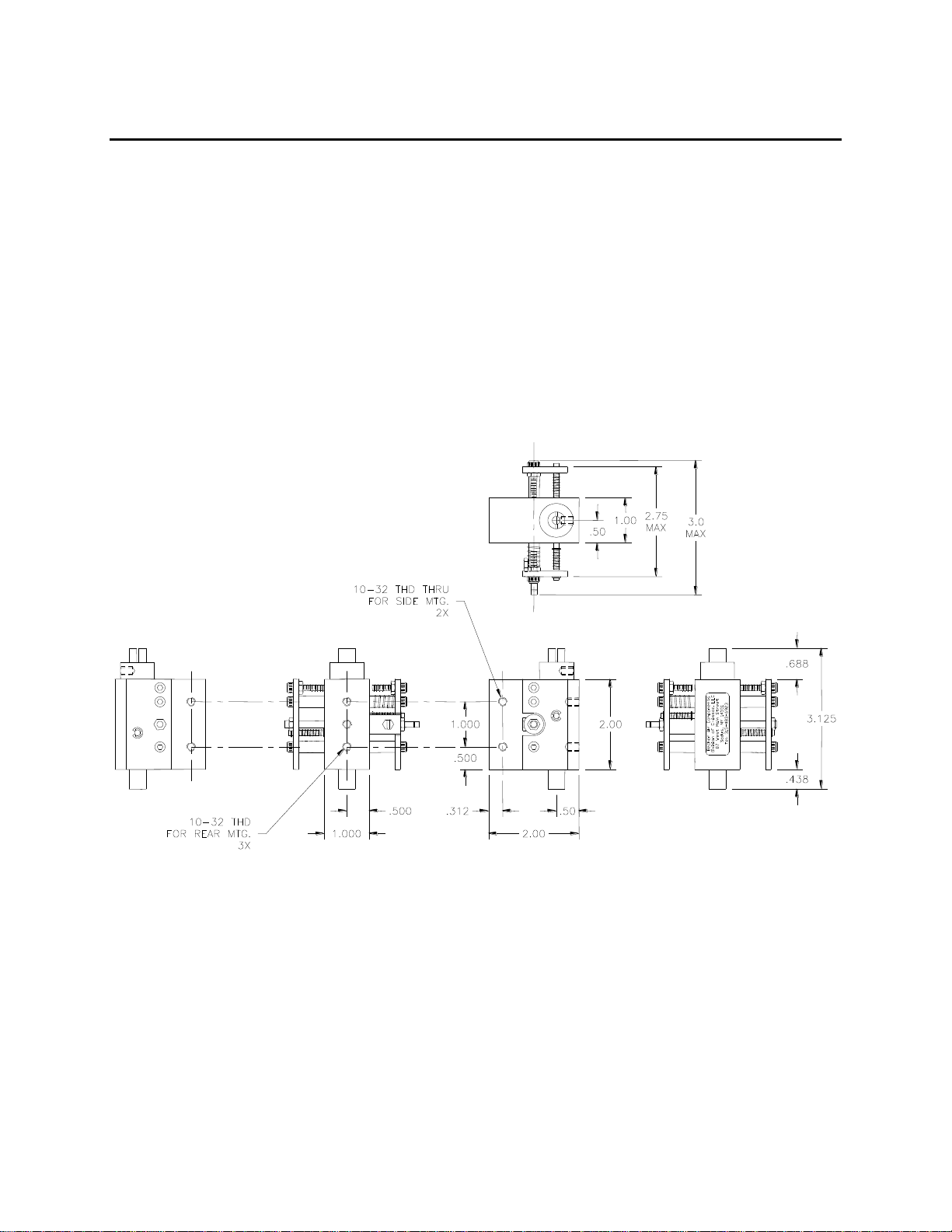
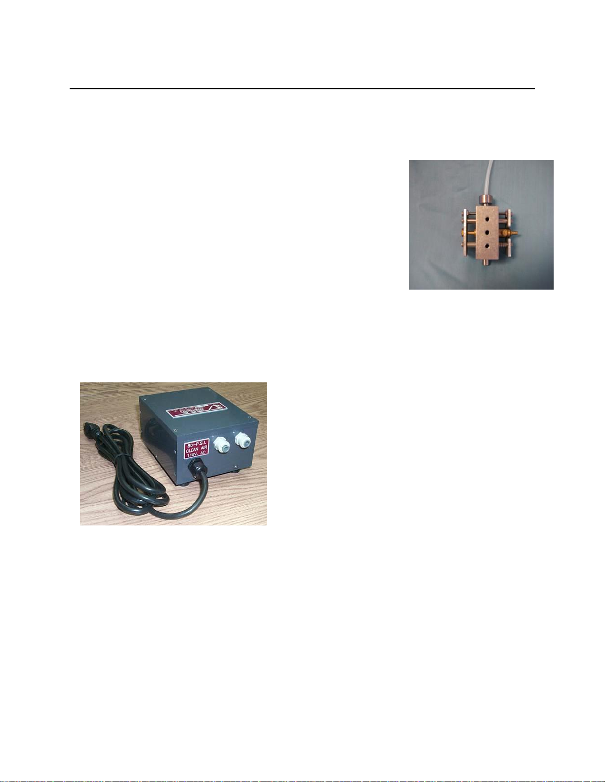
OPTIONAL EQUIPMENT
A standard automatic, single station escapement unit can be
supplied for mounting at an assembly station. Four tapped #10-
32 mounting holes are provided. Units with multiple outlet
escapements can be quoted on request.
The Automatic Escapement is mounted below the spring feeder
and will dispense one (1) spring when activated by an air signal.
The factory supplies this unit with a restricting fitting installed
on the air cylinder. If this fitting is removed, the air signal provided
by the customer must be controlled air. Full line flow/pressure
will damage the unit.
An Automatic Escapement Timer (PN: 69000-775)
may be used to automatically actuate the escapement
at a pre-determined time interval. The time interval
may be varied allowing the customer to dynamically
adjust their spring dispensation rate.
The automatic escapement can also be actuated via an optional Air Operated Foot-Pedal (not
shown). This unit allows the user of an auto escapement to manually dispense a spring as desired
by stepping on the foot-pedal. Depressing the pedal allows air to pass though to the escapement
and thus actuate the solenoid.
12
OPTIONAL EQUIPMENT
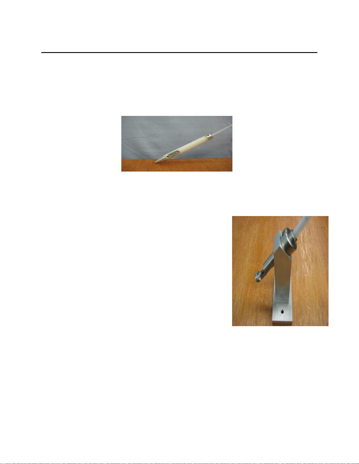
A Pen-type Escapement is available for manually releasing one spring at a time into position.
Units are tooled for specific spring sizes up to .250 inch diameter and .500 inch long.
The Bench-type Escapement provides for dispensing of one
spring at a time for manual pickup and placement.
Available for spring sizes .250 to .500 inch diameter.
13
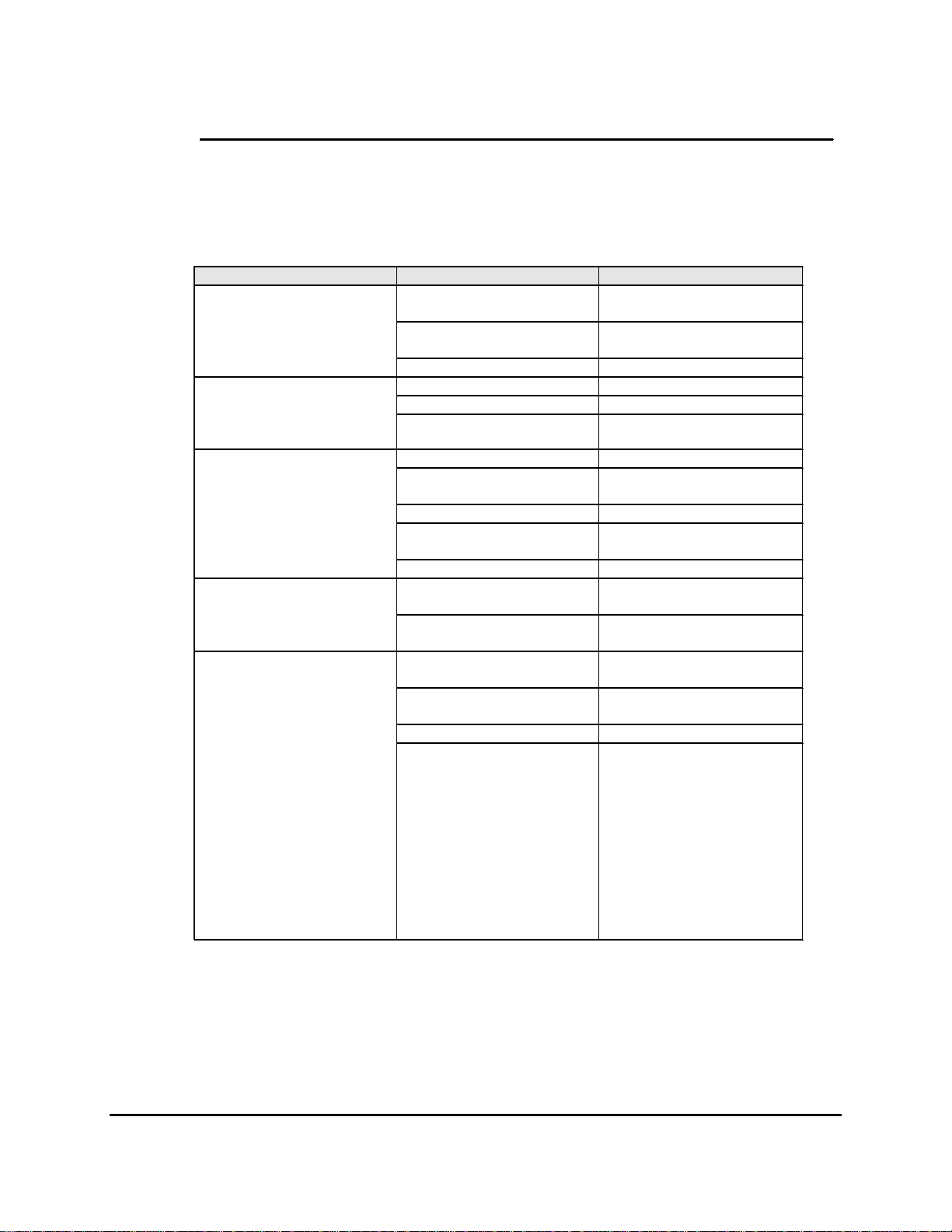
TROUBLE SHOOTING
PROBLEM
CAUSE
SOLUTION
No Power
Check power source, restore
as necessary
Fuse Blown
Remove Base Panel, replace
inline fuse
Unit will not operate,
ON/OFF, Switch does not
light.
Faulty Switch
Replace On/Off Switch
No air to unit
Restore air supply
Timer not cycling
Replace timer
Unit will not operate –
ON/OFF Switch is lit
Air valve not shifting
Replace air valve
Nozzle obstructed
Remove and clear nozzle
Springs oversized or
damaged
Replace springs
Inadequate air supply
Restore supply to 80 p.s.i.
Air leaking around door(s)
Adjust door latch/replace
gasket
Unit runs –will not feed
springs
Window(s) leaking
Replace windows
Supply reservoir over filled
Remove springs to restore
operating level
Unit runs –feed rate
inadequate
Insufficient volume in supply
reservoir
Add springs to restore
operating level
Feed tube kinked, worn or
obstructed
Replace feed tube
Springs have been
magnetized
Remove and degauss springs
Springs dirty or oily
Remove and clean springs
Springs will not feed down
tube
Static charge
Small, light springs are
subject to static charge
buildup. This may become
worse in low humidity
conditions. An occasional
shot of anti-static aerosol can
eliminate this problem. Take
care to not saturate the
springs. Any liquid –water,
oil or solvent will impair
spring feed rates.

14
MAINTENANCE
NOTE 1: It is very important that a clean air supply is maintained. Change all air line filters at
3-month intervals or as required to ensure a continuous clean air supply.
NOTE 2: Never oil any parts on the feeder or escapements, adding oil or lubricants can have a
negative impact on feed rates and could void warranty.
FEEDER MAINTENANCE:
* Once/month. Wipe out inside of feeder using non-ammonia based cleaner to remove
excess dust/dirt buildup. (Required less often if using passivated springs.)
* Once/month. Wipe spring slide ramp with Armor All or Pledge to reduce friction and
ensure springs slide freely. More frequent applications may be required depending on the
cleanliness of the springs be fed.
* Every 3 months. Check/tighten paddlewheel assembly mounting screws if applicable.
* Once/year. Check paddlewheel inserts for wear. Insert should protrude from
paddlewheel body by at least 0.75 inches. (New insert extends 0.84 inches.) If paddlewheel
inserts are excessively worn feeder may have difficulty keeping up with required feed rate. (See
parts list.)
* Once/year. Check door gasket for damage or wear which may cause air leaks at
door/feeder interface. Replace if necessary. (See parts list.)
* Once/year. Check for air leaks around windows. Repair using clear RTV. If a window
is cracked it should be replaced to prevent air leakage. Any air leaks could affect the feeder’s
ability to keep up with the required feed rate. (See parts list.)
TUBING FROM FEEDER TO ESCAPEMENT:
* The tubing, which carries the springs from the feeder to the escapements, will get worn to
a point where the springs have difficulty sliding down to the escapements. The replacement rate
varies depending on spring configuration and feed rate. Monitor system to determine the
required replacement interval.

15
ESCAPEMENT MAINTENANCE:
* Every 3 months. Check all air fittings and tighten if necessary.
* Every 3 months. Check all hardware and tighten if necessary. (If hardware is tightened
on slide rods be careful not to over torque as this could induce twist into assembly causing it to
bind when actuated. Tighten screws on each end of the slide rods to a snug condition then
actuate the escapement by hand to verify freedom of movement throughout the actuation range.
Complete the tightening in a rotational fashion until all screws are tight. After all hardware is
tight verify freedom of movement throughout actuation range.)
16
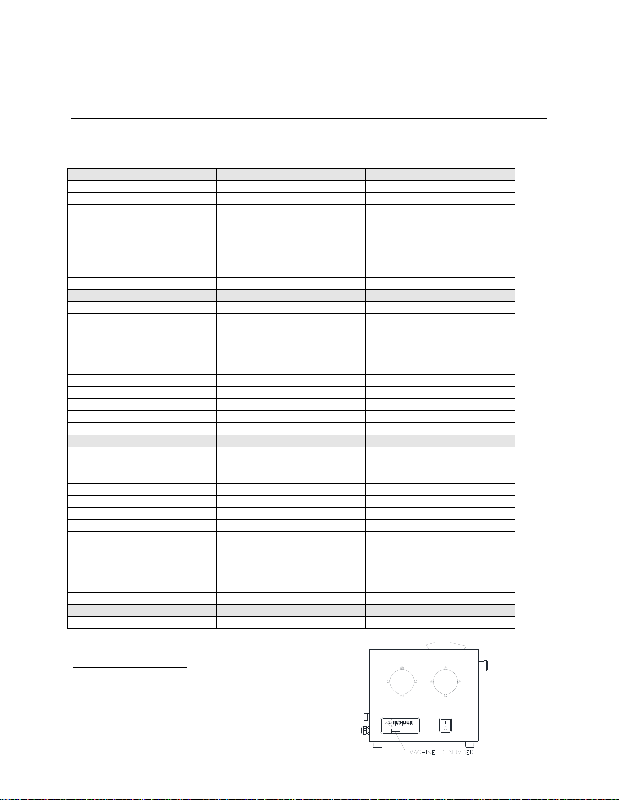
PARTS LIST
MODEL 550
115 VOLT
230 VOLT
AIR VALVE (2)
69000-406
69000-406-01
TIMER
69000-404-05
69000-404-06
ON/OFF SWITCH
69000-403
69000-403
PUSHER CYLINDER
69000-412
69000-412
CYLINDER CLEVIS
69000-576
69000-576
DOOR LATCH
69000-415
69000-415
DOOR SEAL
69000-442
69000-442
WINDOW (4)
69000-572
69000-572
MODEL 600/602
115 VOLT
230 VOLT
AIR VALVE (SM)
69000-406
69000-406-01
AIR VALVE (LG)
69000-405
69000-405-01
TIMER
69000-404-05
69000-404-06
ON/OFF SWITCH
69000-403
69000-403
PUSHER CYLINDER
69000-410
69000-410
CYLINDER CLEVIS
69000-496
69000-496
DOOR LATCH
69000-415
69000-415
DOOR GASKET
69000-442
69000-442
SIDE DOOR GASKET
69000-490
69000-490
WINDOW (4)
69000-616
69000-616
MOTOR
69000-439-01
69000-439-02
MODEL 652
115 VOLT
230 VOLT
AIR VALVE (SM) (2)
69000-406
69000-406-01
AIR VALVE (LG)
69000-405
69000-405-01
TIMER
69000-404-05
69000-404-06
ON/OFF SWITCH
69000-403
69000-403
MOTOR
69000-439-01
69000-439-02
PUSHER CYLINDER
69000-411
69000-411
CYLINDER CLEVIS
69000-496
69000-496
PADDLE WHEEL (5)
69000-694
69000-694
PADDLE WHEEL INSERT (10)
69000-695
69000-695
DOOR LATCH (2)
69000-415
69000-415
DOOR GASKET
69000-442
69000-442
WINDOW (2)
69000-616
69000-616
WINDOW (2)
69000-616-02
69000-616-02
ESCAPEMENT
N/A
N/A
AIR SOLENOID
69000-012
69000-012
Ordering Information
Before calling for parts or service, please have your
machine serial identification number ready.
DIVISION OF C-ASSOCIATES, LLC.
MODEL NO.
SERIAL NO.
WWW.BECHERAIR.COM
SODUS, NY 315-483-6923
17
This manual suits for next models
3
Table of contents
Popular Wire Feeder manuals by other brands

OHTAKE
OHTAKE NSRI Series user manual

MK Products
MK Products Cobramatic Pro Series owner's manual

ESAB
ESAB Origo Feed 304 PIPE instruction manual

Abicor Binzel
Abicor Binzel ABIDRIVE V2 Operating instruction

Afag
Afag HLF12-P Operating and installation instructions

Lincoln Electric
Lincoln Electric DLF-72 Operator's manual
