Afag HLF12-P User manual

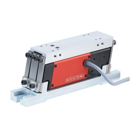
Linear feeder
HLF07-P / 12-P
Translation of operating and installation instructions
Copyright by Afag GmbH

Page 2 16/05/2019 R03.0
This operation instruction applies to:
Type
Order number
Linear feeder
HLF07-P
230 V / 50 Hz
50162932
Linear feeder
HLF12-P
230 V / 50 Hz
50162933
Version of Documentation: BA_HLF07-12-P_R03.0_EN.docx
Release: R03.0
Date: 16/05/2019
Following US patents are registered or announced:
•Linear vibratory conveyor (U.S. Patent No.7,784,604)
•Linear vibratory conveyor (U.S. Patent No.8,051,974)
Following Canadian patents are registered or announced:
•Linear vibratory conveyor Hybrid (CA-Patent No.2,636,171)
•Linear vibratory conveyor (CA-Patent No. 2,636,968)

R03.0 16/05/2019 Page 3
Contents:
1Safety instructions............................................................................................ 4
1.1 Explanation of symbols and notes ............................................................................................................ 4
1.2 Basic safety information ........................................................................................................................... 5
1.2.1 Electrical hook up ............................................................................................................................ 5
1.2.2 Specific danger points ..................................................................................................................... 6
1.3 Intended use ............................................................................................................................................. 6
1.4 Notes for Pacemakers and Defibrillators .................................................................................................. 7
2Description of the device.................................................................................. 8
2.1 General ..................................................................................................................................................... 8
2.2 Functional description............................................................................................................................... 8
2.3 Technical data........................................................................................................................................... 9
3Assembly instructions.................................................................................... 11
3.1 Transport ................................................................................................................................................ 11
3.2 Installing the unit .................................................................................................................................... 11
3.3 Mounting of the useful mass .................................................................................................................. 12
3.3.1 General.......................................................................................................................................... 12
3.3.2 Mounting a linear track................................................................................................................. 12
4Operating instructions.................................................................................... 14
4.1 Feeder track design................................................................................................................................. 14
4.2 Balance of weights.................................................................................................................................. 14
4.3 Piezo control ........................................................................................................................................... 15
4.4 Several Piezo linear conveyors in one feeder: ......................................................................................... 16
4.5 Torques ................................................................................................................................................... 17
5Maintenance Instructions ............................................................................... 18
5.1 Troubleshooting ...................................................................................................................................... 18
5.2 Wear parts and spare parts .................................................................................................................... 21
6Accessories ..................................................................................................... 21
6.1 Mounting parts ....................................................................................................................................... 21
6.2 Control device ......................................................................................................................................... 21
6.3 Ordering address .................................................................................................................................... 22
7Disposal ........................................................................................................... 22

Page 4 16/05/2019 R03.0
1Safety instructions
1.1 Explanation of symbols and notes
Symbols: Assembly and commissioning must be carried out by qualified person-
nel only and according to these operating instructions.
Please observe the meaning of the following symbols and notes. They are grouped into
risk levels and classified according to ISO 3864-2.
DANGER
Indicates an immediate threatening danger.
Non-compliance with this information can result in death or serious
personal injuries (invalidity).
WARNING
Indicates a possible dangerous situation.
Non-compliance with this information can result in death or serious
personal injuries (invalidity).
CAUTION
Indicates a possibly dangerous situation.
Non-compliance with this information can result in damage to prop-
erty or light to medium personal injuries.
NOTE
Indicates general notes, useful operator tips and operating recom-
mendations which don’t affect safety and health of the personnel.

R03.0 16/05/2019 Page 5
1.2 Basic safety information
Familiarity with these basic safety rules and regulations constitutes the fundamental
prerequisite for safe handling and trouble-free operation of Afag HLF-P linear feed-
ers.
These operating instructions contain the most significant regulations for safe HLF-P
operation. These operating instructions - and in particular the safety regulations -
must be observed by anyone working on and with the HLF-P. The applicable on-site
accident prevention rules and regulations must also be observed. These operating
instructions must always be kept handy where the HLF-P is operated.
Operation of the hopper is only to be carried out by technically qualified personnel.
Qualified personnel are deemed to be persons who, by reason of their training, expe-
rience and instructions as well as their knowledge of the prevailing standards, regula-
tions, accident prevention regulations and operational conditions, have been author-
ized by the people responsible for the safety of the system to perform the required
activities, and who are capable of recognizing possible hazards and avoiding them
(definition of qualified personnel as per IEC 364).
Any malfunctions that may have an adverse effect on the safety of any persons, the
HLF-P or other material assets must be eliminated without delay.
The following instructions are not only intended to ensure the personal safety of the
operators but also the operation of the products described and the devices connect-
ed to them:
1.2.1 Electrical hook up
NOTE
•Disconnect the power supply prior to assembling or dismantling
as well as when changing fuses or carrying out installation mod-
ifications.
•Observe all current accident prevention and safety regulations
applicable to particular cases of operation.
•Check whether the rated voltage of the hopper coincides with
the local power supply prior to putting into operation.
•All E-Stops must remain effective for all modes of operation. Un-
locking the E-Stops must not, under any circumstances, cause
uncontrolled restarting of the hopper.
•The electrical connections must be safeguarded!
•Ground wires must be checked for proper function subsequent
to assembly!
•Hook-up is only to be carried out by authorized personnel.

Page 6 16/05/2019 R03.0
1.2.2 Specific danger points
NOTE
Afag HLF-P linear feeders are state-of-the-art equipment designed in
compliance with the EU Machinery Directive and accepted safety
regulations. Nevertheless, however, risks may arise from using this
equipment that may endanger life and limb of user or third parties
and cause interference with the HLF-P or other material assets.
1.3 Intended use
The HLF-P is intended exclusively for the transporting and buffering of components
and can also be used for component sorting. For maximum permissible dimensions
and weights of add-on components, observe details in chapter 2.3 Table 1: Technical
data, chapter 3 Assembly instructions and chapter 4 Operating instructions. Appro-
priate use also includes observation of all Notes in these operating instructions.
WARNING
The KLF may not be used:
a) in damply and wet area
b) in temperature lower than 10°C or higher than 45°C
c) in areas where readily flammable media are present
d) in areas where readily explosive media are present
e) in heavy polluted or dust- laden area
f) in aggressive area (e.g. saliferous atmosphere)
None modification or reconstruction are allowed. The Tracks (in the chapter 4.1
Feeder track design and in the chapter 3.3 Mounting of the useful mass) as well as
the accessories (chapter 6) are excluded from this arrangement.
NOTE
Any use other than that described above is deemed to be improper
and will cause the warranty to terminate.
Also refer here to our general terms and conditions of sale.

R03.0 16/05/2019 Page 7
1.4 Notes for Pacemakers and Defibrillators
Afag vibration conveyors are tested in accordance with regulation 15 of the German Statuto-
ry Accident Insurance Association [Deutsche Gesetzliche Unfallversicherung, DGUV] (previ-
ously BGV B11 of German Accident Prevention Regulations). The permissible values of ex-
posure area 2 are not exceeded, therefore no measures are required pursuant to Section 4
(2) of the DGUV regulation 15. The definitions of Section 12 “Indirect Effects, Medical Im-
plants” remain unaffected by the above.
The alternating magnetic fields that occur in the immediate vicinity of certain vibration con-
veyors may affect the proper functions of active implants, i.e. pacemakers and defibrillators.
Anyone with active medical implants, for which no individual risk assessment has been pro-
vided, must observe the specified safety distances to the vibration conveyors. The distances
each relate to the position of the upper body and the active medical implant relative to the
field source.
Type
Safety Distance
HLF07-P / HLF12-P
--

Page 8 16/05/2019 R03.0
2Description of the device
2.1 General
Afag Type HLF-P Linear Feeders are used to remove parts from upstream machines
and/or feed parts to downstream machines. Afag Linear Feeders are also used for
sorting parts, with due consideration of various criteria. Linear feeders are fitted in in-
dividual feeding units as well as in complex assembly systems.
The different types of Linear Feeders vary in size and application (see Table 1:
Technical data)
NOTE
The HLF-P may only be operated with the Afag Piezo controller PSG-
1. The PSG1 is adapted to the specific operating parameters of the
Piezo element. Operation with another controller will result in de-
struction of the Piezo element.
2.2 Functional description
HLF-P devices consist of two oscillating parts arranged on top of each other which
oscillate asynchronously. Slotted leaf springs connect these to a common base plate
at which the opposing oscillating forces virtually cancel each other out. The oscillat-
ing part on top is used as a structure (working weight) for attaching the feeder track.
The lower oscillating part is the counterweight.
A Piezo drive unit is mounted horizontally between the two oscillating parts. The fa-
vourable characteristics of the HLF-P linear conveyors are based on the high operat-
ing frequency which enables smaller amplitudes of oscillation and thus a smoother
conveyance with utmost precision. A further advantage of this device is the mass
balance between useful mass and opposing mass which eliminates free reactive
forces directly at the unit.

R03.0 16/05/2019 Page 9
2.3 Technical data
Figure 1: Dimensions HLF-P

Page 10 16/05/2019 R03.0
Table 1: Technical data
Description
Units
HLF07-P
HLF12-P
Dimension
A
[mm]
400
500
B
[mm]
25
30
C
[mm]
10
10
D1
[mm]
7
9
D2
[mm]
4 x M5
4 x M5
D3
[mm]
2 x 4H7
2 x 4H7
E
[mm]
36
42
F
[mm]
73
80
G
[mm]
80
100
H
[mm]
50
59
K
[mm]
60
80
M
[mm]
170
200
N
[mm]
2 x 4H7
2 x 4H7
P
[mm]
150
180
Ideal track weight
[kg]
0,7 ± 0,05
1,2 ± 0,05
Max. track weight
[kg]
1,0
1,4
Weight of basic device
[kg]
1,8
3,0
Mech. osc. frequency
[Hz]
220-240
190-210
Power supply
[V/Hz]
230 V, ±10%, 50 / 60 Hz
Max. power consumption
[VA]
7,5
7,5
Degree of protection
-
IP 54
Control device (not in scope of deliv-
ery)
-
PSG1
Temperature range for operation
[C°]
+10 to +45
Noise emission: Continuous noise
pressure level (without transported
material)
[dB]
<70
Measuring height/measuring distance
[m]
1,6/1
Measurement direction with respect
to the noise source
[°]
90
Measurement method
-
A-evaluation
Various sizes are available (see Table 1: Technical data) depending on the area of
application and available space. The main criterion is the working weight (track
length) and the space available for installation.
The Afag Piezo linear conveyors are designed for connection to 230 V, ±10%, 50 /
60Hz. The Afag Piezo controllers PSG-1 are available for controlling the linear con-
veyors (see chapter 6.2 Control device).

R03.0 16/05/2019 Page 11
3Assembly instructions
3.1 Transport
WARNING
Improper use of transport means (industrial trucks, cranes, technical aids,
sling gear etc.) may lead to bruises and other injuries.
Required behaviour:
-Observe and follow the transport and maintenance instructions
-Proper use of transport means
CAUTION
During transport, the linear feeder must only be held by the base.
The linear track is no lifting point.
3.2 Installing the unit
The HLF-P is firmly screwed to the foundation structure by means of slots provided in
the base plate (see Figure 2). This precisely defines the interfaces where the feeder
track enters and exits as well as allowing adjustment. The substructure should be
non-oscillating in a horizontal plane in order to be able to take up any residual forces.
Self-supporting profile constructions have to be reinforced with a base plate to which
the Linear Feeder is attached. A steel plate of at least 20mm thickness and a width of
over 120mm should be used for this purpose. The vertical oscillating forces respon-
sible for energy induction in the foundation structure should be virtually completely
eliminated by a careful balance of weights (see chapter 4.2 Balance of weights).
Height adjustments can be achieved by means of appropriate substructures. Stand-
ard Afag components are available for setting up complete units.
Figure 2: Attachment slots in the base plate
Slots for attaching the HLF-P

Page 12 16/05/2019 R03.0
3.3 Mounting of the useful mass
3.3.1 General
The HLF-P Linear Feeder is based on a balance of the oscillating forces by the prin-
ciple of opposing oscillation (push-pull). In order to ensure an effective balance of os-
cillating forces, it is necessary to keep the lines of action of the centres of gravity of
the working weight and counterweight as close together as possible. The position of
the centre of gravity of the counterweight is determined by the Linear Feeder design.
The centre of gravity of the working weight is determined by the construction design
specified for the working weight (e.g. feeder track). In order to ensure a good balance
of oscillating forces with minimum residual oscillation, the overall centre of gravity of
the working weight has to be located within the area specified in Table 2: Limiting co-
ordinates for the position of the centre of gravity of the working weight.
Figure 3: Centre of gravity range
= centre of gravity of useful mass
Table 2: Limiting coordinates for the position of the centre of gravity of the working weight
HLF07-P
HLF12-P
Dimension [mm]
XS
85±10
105±10
Dimension [mm]
YS
0±9
0±10
Dimension [mm]
ZS
77±8,5
84±11
3.3.2 Mounting a linear track
The feeder track is attached by means of a side plate (see Figure 4). The side plate
is fixed precisely and reproducibly using fitting pins. Vertical slits in the side plate are
provided for feeder track attachment, allowing fine adjustment of the track entry and
exit interfaces in a vertical direction.

Page 14 16/05/2019 R03.0
4Operating instructions
The first step in adjusting the linear feeders is always to balance the masses and
then to adjust the natural frequency.
4.1 Feeder track design
The linear tracks must be unyielding so that the transport pulses generated by the
unit are fully transferred to the work pieces and no superimposed natural vibration
can adversely affect the transport process. This requirement has priority over mass
reduction measures. The preferred material for linear tracks is tool steel (e.g. 1.2842,
90MnCrV8). Linear track design should adhere to the useful masses specified in
chapter 2 Table 1: Technical data and Table 4: Obligatory values for the working
weight
The following size ratio should be aimed for with regard to the feeder track cross-
section:
𝐻𝑒𝑖𝑔ℎ𝑡
𝑊𝑖𝑑𝑡ℎ =2,5
1
The recommended dimensions are listed in Table 3: Linear track dimensions. The di-
mensions are for one vibrating section and can be applied to each of the two vibrat-
ing sections.
Table 3: Linear track dimensions
HLF07-P
HLF12-P
Height [mm]
400
500
Width [mm]
17
17
4.2 Balance of weights
The oscillating forces in the base plate of the Afag Linear Feeder are compensated
almost completely due to the principle of opposing oscillations (push-pull). This bal-
ance of oscillating forces is however only achieved if:
1. The working weight and the counterweight are balanced as closely as possi-
ble.This means that the working weight and the counterweight are equal. The work-
ing weights specified for respective sizes are listed in Table 4: below. The working
weight is the total weight of all components attached to the mounting plate including
the side plate. The balance of weight is verified by simply weighing the working
weight.
2. The centre of gravity of the working weight is located in the range represented in
Figure 3.
Both conditions have to be taken into consideration at the construction stage of the
feeder track. An optimal balance of weight is achieved when almost no residual vibra-
tions can be detected in the substructure.

R03.0 16/05/2019 Page 15
Table 4: Obligatory values for the working weight
Type
Ideal useful mass [kg]
Max. useful mass [kg]
HLF07-P
0,7 ± 0,05
0,9
HLF12-P
1,2 ± 0,05
1,4
NOTE
Useful and counter masses should correspond to the values speci-
fied in Table 4: .
NOTE
1. Masses are fully balanced if hardly any vibrations are noticea-
ble in the floor.
2. When masses are fully balanced, the transport speeds at use-
ful and counter sides are identical.
4.3 Piezo control
The Afag Piezo linear conveyor is a spring and mass vibration system and works by
taking advantage of the resonance behaviour. Please proceed as follows in order to
achieve a stable operating point with the desired conveying capacity when adjusting
the control parameters (voltage and operating frequency):
1. Start settings: Voltage 80% and operating frequency according to Table 1:
Technical data
2. Find the resonance point by increasing or decreasing the operating frequency
from the start setting. The resonance point is at the frequency with the highest
amplitude of the vibration system.
3. Set the operating frequency above the resonance point in 0.1 Hz increments
depending on the conveying capacity required, i.e. increase the operating fre-
quency from the resonance point until the required conveying capacity is
reached. The greater the distance between operating frequency and reso-
nance point, the more insensitive is the operating point to external disturb-
ances.
4. Fine-adjustment of the conveying capacity is possible by changing the voltage.
Set the voltage as low as possible in order to save the Piezo.
The same conveying capacity can be reached by different combinations of the oper-
ating parameters “voltage” and “operating frequency”. The optimum setting as re-

Page 16 16/05/2019 R03.0
gards stability, care of the Piezo and mutual influence (with several devices) for the
required conveying capacity must be determined depending on the application.
CAUTION
The operating frequency must be higher than the natural frequency
of the Piezo linear conveyor. If the operating frequency is the same
as the natural frequency, i.e. if the Piezo linear conveyor is operated
at the resonance point, the Piezo drive unit will be destroyed in the
medium term.
NOTE
Readjustment of the conveying speed according to the above dia-
gram can become necessary for new devices 48 hours after start-up.
We recommend to carry out a simple stability test after having set the operating pa-
rameters (voltage and frequency): If the running linear conveyor is manually stopped
for a short time (external fault), the HLF-P must return automatically to the previously
set conveying capacity (amplitude) after it was released again. If this is not the case,
the required conveying capacity should be set by selecting other operating parame-
ters (e.g. resonance point: 200.8Hz; previous operating point: 70% / 201.5Hz ➔new
operating point 82% / 202.2Hz); afterwards the stability test should be repeated.
4.4 Several Piezo linear conveyors in one feeder:
If several Piezo linear conveyors are operated on the same base plate / subbase the
linear conveyors may interfere with each other. This can be noticed from an unstable
conveying capacity or the conveying behaviour of parts in the rail. The interference
can be eliminated by operating all linear conveyors at the same operating frequency.
The required conveying capacity of the individual HLF-Ps must be guaranteed. This
can be achieved by changing the voltage. Please see the following example for more
details: Original situation: two HLF-Ps on one base plate with the operating point
70% / 202.4Hz (1st HLF-P) and 82% / 203.0Hz (2nd HLF-P) ➔new operating points
with the same operating frequencies and adapted voltages: 75% / 202.7Hz (1st HLF-
P) and 79% / 202.7Hz (2nd HLF-P).

R03.0 16/05/2019 Page 17
4.5 Torques
Tightening torques MSp in Nm for shank screws with metric ISO control threads and
head supports according to DIN 912 or DIN 931:
Tightening torques MSp in Nm
Screw
Strength class 8.8
Strength class 10.9
Strength class 12.9
M4
2,8
4,1
4,8
M5
5,5
8,1
9,5
M6
9,5
14,0
16,5
(M7)
15,5
23,0
27,0
M8
23,0
34,0
40,0
M10
46,0
68,0
79,0
M12
79,0
117,0
135,0
M14
125,0
185,0
215,0
M16
195,0
280,0
330,0
M18
280,0
390,0
460,0
M20
390,0
560,0
650,0
M22
530,0
750,0
880,0
M24
670,0
960,0
1120,0
M27
1000,0
1400,0
1650,0
M30
1350,0
1900,0
2250,0
By: Dubbel (18th edition), page G175

Page 18 16/05/2019 R03.0
5Maintenance Instructions
An HLF-P type linear conveyor requires minimal maintenance. Depending on the
manner in which it is used, signs of wear may occur, which can be compensated for
by resetting the adjustment plates.
Spring wear/ oxidation (increased resonance frequency)
Depending on the operating mode and environment, a layer of oxidation may develop
on the springs at the contact surfaces which over time may adversely affect the vibra-
tion behavior. In cases such as these, the resonance frequency will increase and it
may be necessary to compensate for the increase by lowering the adjustment plates.
Spring setting behavior (reduced resonance frequency)
The result of longer storage periods may be that installed springs can show a setting
behavior, and in consequence a reduction in the spring stiffness and reduced reso-
nance frequency. In this case, the resonancy frequency can be re-calibrated, which
may cause the spring stiffness to be reduced as well as a drop in the resonance fre-
quency.
In some cases, it may be necessary to remove the leaf springs to clean them or, if
they are heavily worn, to replace them entirely. Here, the vibration parts must be
supported in vertical direction. Then, only one spring package at a time may be re-
moved, because otherwise the vibration parts would move, making it impossible to
guarantee that they function properly.
CAUTION
The leaf springs must not be oiled or greased as this would make the
springs sticky and in turn adversely affect the vibration response.
5.1 Troubleshooting
Conveyor does not run, there is no vibration detectable
Cause of fault
Fault repair
Connection to the power supply interrupt-
ed
Check the connection between drive control unit and
control mains adapter
Control unit is switched off <0>
Switch on the control unit <1> or check the jam con-
trol signal if a jam control is used
Control unit is defective
Electrical check of the device, use an exchange or a
replacement unit
The Piezo is damaged, or destroyed
Replace the Piezo drive unit. Check settings, see Ta-
ble 1: Technical data and Table 4: Obligatory values
for the working weight
Foreign part jammed in the air gap be-
tween useful and counter mass.
Remove foreign part

R03.0 16/05/2019 Page 19
Conveyor runs too slowly, there is no movement recognisable
Cause of fault
Fault repair
Output frequency of the control unit is set
improperly
Set the frequency in the control unit according to the
required frequency.
The conveyor rail is not sufficiently fas-
tened to the corresponding drive
Tighten fastening screws, check thread, if necessary
The Piezo is damaged, or destroyed
Replace the Piezo drive unit. Check settings, see Ta-
ble 1: Technical data and Table 4: Obligatory values
for the working weight
Change of the system's natural frequency
due to a broken spring
Undo screws of the spring assemblies, check springs,
replace broken or damaged springs. CAUTION!
Cause for a broken spring is often too high oscillation
amplitude. --> Check oscillation amplitude!
The drive is improperly adjusted, i.e. the
system's natural frequency does not
match the exciting frequency
Adjust the drive by changing the spring stiffness, the
position of the adjustment plates or by setting the os-
cillation frequency with the controller. Tighten the
screws of the spring assemblies. CAUTION! Adjust
the conveyors according to the operating manual!
Foreign part jammed in the air gap be-
tween useful and counter mass.
Remove foreign part
The conveying behaviour is instable, the conveyor speed varies
Cause of fault
Fault repair
Output frequency of the control unit is set
improperly
Set the frequency in the control unit according to the
required frequency.
The conveyor rail is not sufficiently fas-
tened to the corresponding drive
Tighten fastening screws, check thread, if necessary
The Piezo is damaged, or destroyed
Replace the Piezo drive unit. Check settings, see Ta-
ble 1: Technical data and Table 4: Obligatory values
for the working weight
Change of the system's natural frequency
due to a broken spring
Undo screws of the spring assemblies, check springs,
replace broken or damaged springs. CAUTION!
Cause for a broken spring is often too high oscillation
amplitude. --> Check oscillation amplitude!
The drive is improperly adjusted, i.e. the
system's natural frequency does not
match the exciting frequency
Adjust the drive by changing the spring stiffness, the
position of the adjustment plates or by setting the os-
cillation frequency with the controller. Tighten the
screws of the spring assemblies. CAUTION! Adjust
the conveyors according to the operating manual!
Foreign part jammed in the air gap be-
tween useful and counter mass.
Remove foreign part
The conveyor transmit vibrations
Cause of fault
Fault repair
The conveyor rail is not sufficiently fas-
tened to the corresponding drive
Tighten fastening screws, check thread, if necessary

Page 20 16/05/2019 R03.0
Change of the system's natural frequency
due to a broken spring
Undo screws of the spring assemblies, check springs,
replace broken or damaged springs. CAUTION!
Cause for a broken spring is often too high oscillation
amplitude. --> Check oscillation amplitude!
The drive is improperly adjusted, i.e. the
system's natural frequency does not
match the exciting frequency
Adjust the drive by changing the spring stiffness, the
position of the adjustment plates or by setting the os-
cillation frequency with the controller. Tighten the
screws of the spring assemblies. CAUTION! Adjust
the conveyors according to the operating manual!
Conveyor rail lifts off or hits
Cause of fault
Fault repair
The conveyor rail is not sufficiently fas-
tened to the corresponding drive
Tighten fastening screws, check thread, if necessary
Foreign part jammed in the air gap be-
tween useful and counter mass.
Remove foreign part
Change of the system's natural frequency
due to a broken spring
Undo screws of the spring assemblies, check springs,
replace broken or damaged springs. CAUTION!
Cause for a broken spring is often too high oscillation
amplitude. --> Check oscillation amplitude!
The drive is improperly adjusted, i.e. the
system's natural frequency does not
match the exciting frequency
Adjust the drive by changing the spring stiffness, the
position of the adjustment plates or by setting the os-
cillation frequency with the controller. Tighten the
screws of the spring assemblies. CAUTION! Adjust
the conveyors according to the operating manual!
This manual suits for next models
1
Table of contents
Other Afag Wire Feeder manuals
Popular Wire Feeder manuals by other brands

Barry-Wehmiller
Barry-Wehmiller Thiele Technologies Streamfeeder Reliant... manual

ESAB
ESAB Origo Feed 304 M12 Series Service manual

Oliver
Oliver APF0038 owner's manual

Plockmatic
Plockmatic FeederPro 1000 Operator's manual

Lincoln Electric
Lincoln Electric FLEX FEED 74 HT Operator's manual

Förster-Technik
Förster-Technik TAK5-CH2-25 Original operating instructions