b
THEMICROBOOSTERONBOARDPREAMP
INSTALLATIONMANUAL
SPECIFICATIONS
Inputimpedance:>1MΩ
OutputImpedance:~100Ω
FrequencyResponse:10Hz–30KHz(flat)
ToneStack:Centerfrequency720Hz,Lows+/‐6dB@70Hz,Highs+/‐
6dB@3.5KHz(nofrequencychangeincenterposition)
THD:0.2%(+0Buin/+15dBuout,1.0kHz,600ΩLoad,18VDCpower)
OptimalBatteryVoltage:9VDC±20%upto20VDC
RecommendedBattery:9VAlkaline(or2batteriesinseriesfor18V)
PowerConsumption:<0.1mAh@9VDC
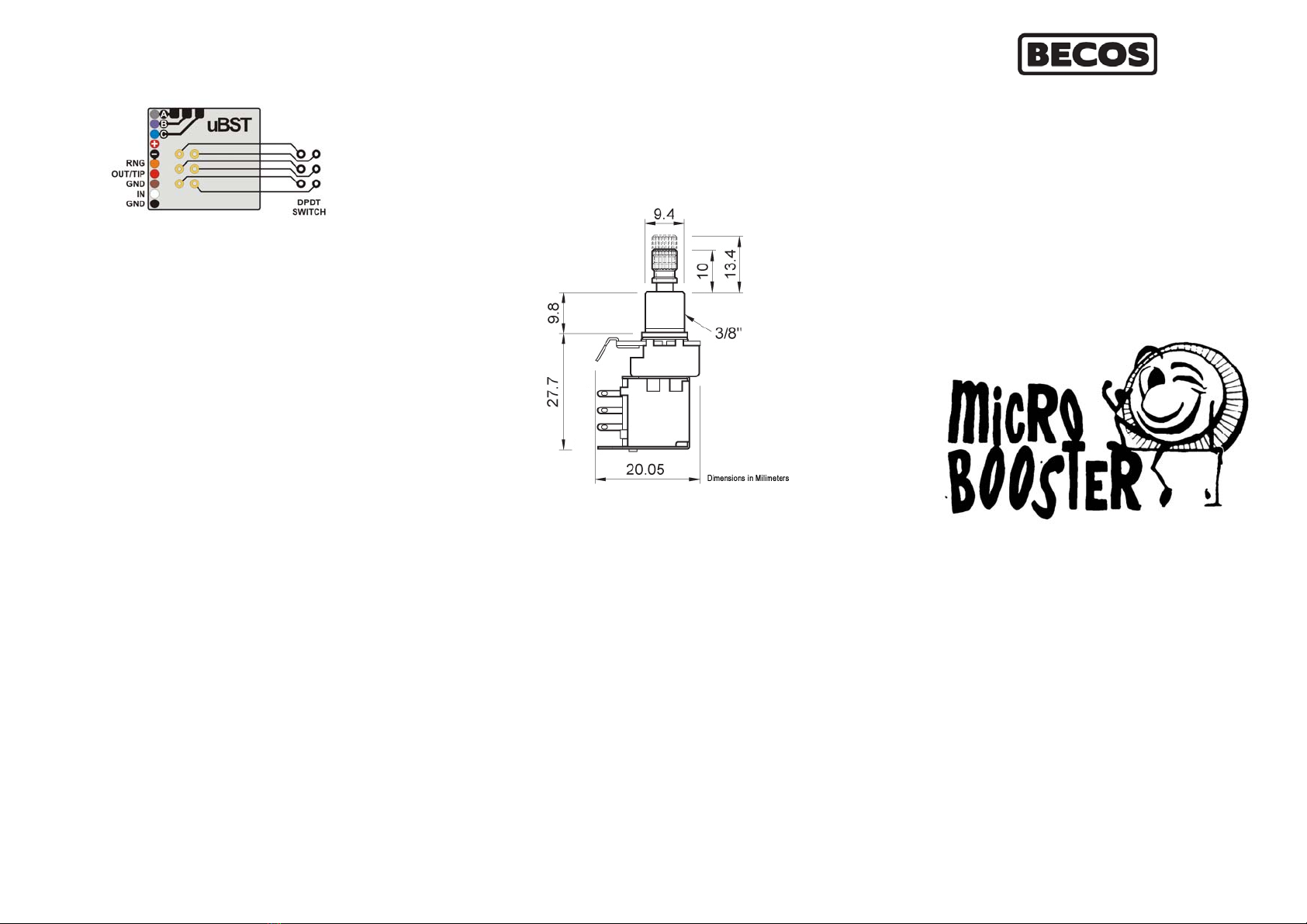
ProductSize49.3mm(length),31.6mm(depth),27.7mm(height)
ProductWeight:54gr.
PackedWeight:160gr.
ADVICE,WARNING&CAUTIONS
‐Readthismanualbeforeinstallationandkeepithandy.
‐Neverpullupthepush‐pushswitch‐potbyforce.
‐Removetheknobfromtheswitch‐potonlywhenswitchisinUP
position.
‐Donotattempttoremovetheshieldingcoveranddamagethe
board.
‐Donotoverheatthecircuitboardsoranyelectroniccomponent.
‐Ifsharptoolsaretobeusedininstallation,handlewithcareand
neveruseforcetohavethingsdone.
‐Wemaychangeproductsspecifications,design,andfeatures
withoutnotice.
INTRODUCTION
Built with monolithic amplifiers employing bipolar technology with
innovativehigh‐performanceconceptsforpristineaudio,theMicro
BoosterMK4hasanexceptionalfrequencyresponseandextremely
lownoise&distortion.
TheMicroBoosterMK4integratesaBaxandalltonestackwhichadds
flexibility for independent tonal tweaking of Lows and Highs. With
mildadjustabilityof +/‐9dB at 70Hz and2.5KHz beforethe0‐16dB
variable general Gain, it can be configured asa Clean Flat Boostor
Mid Boost, Treble Boost, Lows Boost, Boosted V‐Cut, etc. without
going into extremes. With tone knobs centered, the boost is
completelyflat.
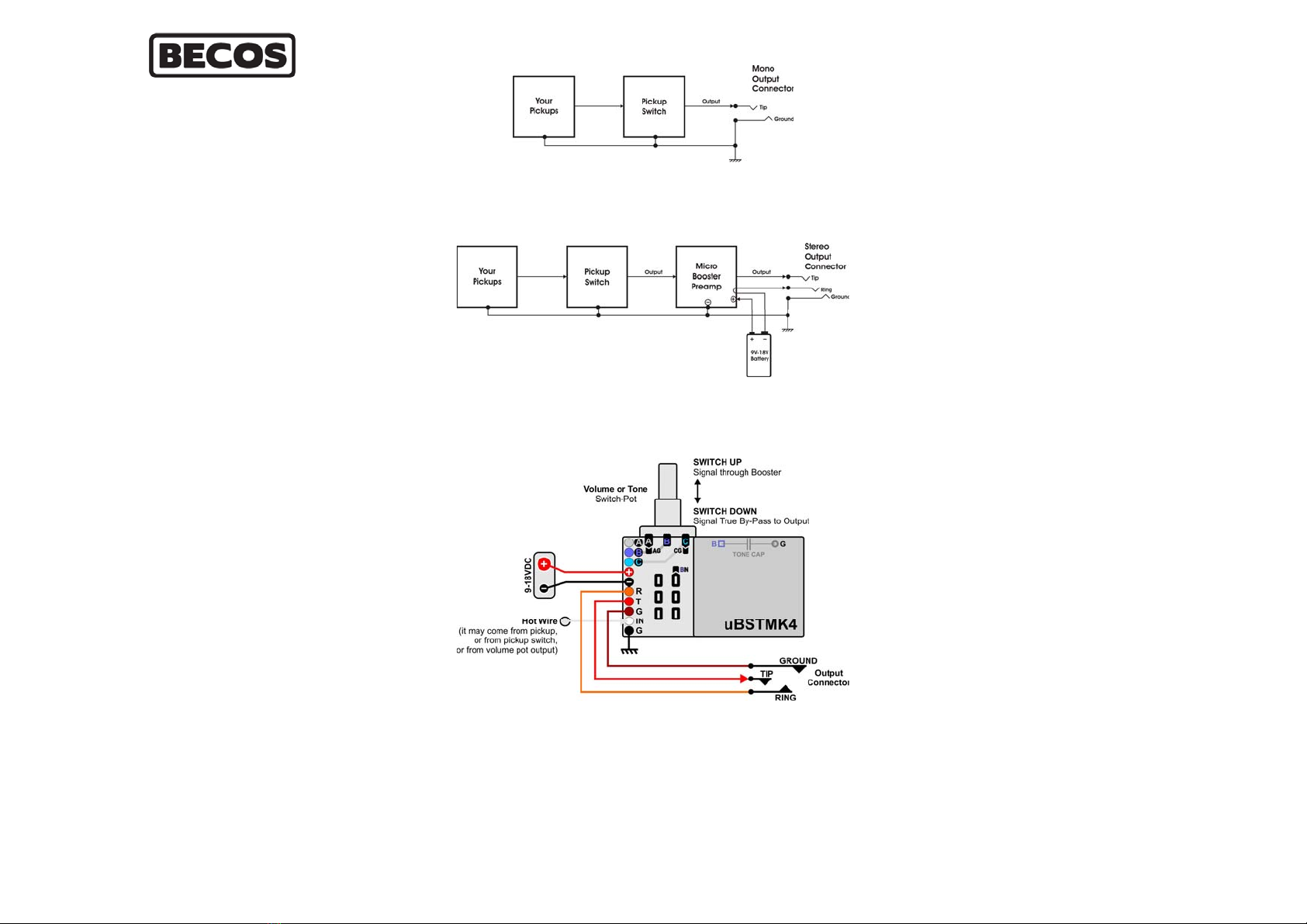
Usually,aninstrumentiswiredlikethis:
The booster will come latest in the guitar signal path, after the
pickups,volume&tonecontrols,pickupswitchandthemainsignal
willbefedthroughoneHotWireandGround.
An optional Push‐Push switch‐pot may be soldered directly on the
electroniccircuitboard.Iftheswitch‐potisnotused,aDPDTswitch
mustbewiredtotheboardtoperformsignalroutinginstead.
The potentiometer side of the switch‐pot IS NOT part of booster's
circuit,andismeanttoreplacevolumeortonepotentiometerin
yourinstrumentfortheconvenienceofhavingaroutingswitchanda
potentiometerinonedevice.Thepotentiometerhastoberewired
justasitusedtobe‐passive.Ifitisthetonecontrolthatisputin
placeof,thetonecapacitorhastobemovedtothenewpotaswell.
A 10‐pin header connector is available on booster's PCB where all
the wiring should be connected. Several wires can be directly
solderedtotheboard,ifapermanentconnectionisdesired.
A, B, C ‐ corresponding to potentiometer lugs (which will replace
actualpotentiometerinyourguitar).ThisiswherewiresGray,Purple
andBluewillbeconnected(thecolorsmaybedifferent,buttheyare
just wires connecting the new potentiometer to the rest of the
instrument’scircuit.Thesepinsintheheaderconnectoraredoubled
byconnecting holes on the circuit boardifsolderingthewiresmay
seem a better option. They also helpto install the capacitor or the
hotwire,dependingofwhereyouinstalltheboosterinyourguitar.
+and‐forconnectingthebattery.Redwireispositive,Blackwireis
negative.
RNG(ring),OUT(tip),GND with corresponding wires (usually
Orange, Red, and Brown) connectthenewTRS‐type(Tip,Ring,
Sleeve)outputconnectortothe board.Thisconnectorreplacesthe
originalTS‐typeofconnector(Tip,Sleeve)ontheinstrument.ATS‐
type mono jack is required to switch the power to the booster. A
TRS‐typeofjackwillnotwork.WhentheinstrumentcableTSjackis
inserted, the Ring to Ground in the connector is shorted by the
instrument plug’s Sleeve and the booster is powered (it stays
poweredregardlessofthepush‐pushswitchposition,upordown).
INandGNDarethepointswheretheHotWire(usuallyWhite)and
theGroundWire(usuallyBlack)willbeconnected.TheGroundWire
should be connected to instrument’s main ground. No other
groundingconnectionisneededtotheBooster.
Severalshortcutpointsontheboard(AtoGround,CtoGround,and
BtoInput)maybeusedtoavoidusingmorewires, whenpossible.
Simplyshorttheseinterconnectingpointswithadropofsolder.
Forsomesetups,theToneCapacitormaybeinstalleddirectlyonthe
booster’s board (in between BpotwiperandGround).TheTone
Capacitorcanonlybesolderedfromtheoutsideoftheboardwhere
thecapacitorismarkedontheboard.Donotattempttoremovethe
shieldingcoverbecauseyouwillriskdamagingtheboard.
PREPARATION
We recommend shielding the electronics compartment in your
instrument with conductive sticky cooper foil if it's not done from
thefactoryalready(aluminumworksbetterthannothing).Besure
to connect this shielding to guitar's main ground point. Shielding is
notnecessaryfortheboosterbutfortheloosewiresinthearea,
whicharenotproperlyshielded.Suchwiresmaybecomeanantenna
andtransfertheEMinterferencetothebooster.Youmayusethe
free Ground point on the booster board as the Main Ground Point
whereallgroundsaretobeconnected.
THENO‐POTBOOSTER