behr Labor-Technik behrotest R 304 User manual
behr
Labor-Technik
R 304
R 306
R 104 S
R 106 S
R 254
R 256
behrotest®
In-Line Extraction Units
User’s Manual

Please read this User’s Manual carefully before using your new behrotest® In-Line extrac-
tion apparatus!
The User’s Manual provides you with clear and simple instructions for using the apparatus.
Additional information, which is useful and important for an understanding of the operation
of the apparatus is denoted in the manual by a gray stripe in the margin.
In the interest of insuring safe utilization of the In-Line-Extraction apparatus, observe care-
fully the safety warnings in the manual, which are designated by an exclamation mark !
We wish you success and satisfaction in the use of your
behrotest®
In-Line Extraction apparatus

Safety Warnings
Always use the extraction apparatus in a fume hood! Release of solvent vapors is
possible!
To avoid electrical shock risk, insure that no liquids come into contact with the
electrical power cable or get into the inside of the electrical components!
Exercise appropriate caution in working with chemicals! Observe the warnings and
guidance in the Material Safety Data Sheet (MSDS) carefully!
Exercise due care and observe pertinent safety regulations in working with glass
components!
To avoid burn injury, do not touch the solvent vessel or extractor with your bare
hands immediately after an extraction; they will be hot!
To avoid risk of re and explosion, under no circumstances should solvent be
poured on the hot heating unit!

Safety Warnings .................................................................................................. 3
1 Description ............................................................................................... 5
2.1 Completeness and absence of damage ............................................................... 6
2.2 List of Components............................................................................................... 6
Basic unit for four or six samples....................................................................................... 6
R 304 ................................................................................................................................. 6
R 306 ................................................................................................................................. 7
R 104 S.............................................................................................................................. 7
R 106 S.............................................................................................................................. 7
R 254 ................................................................................................................................. 7
R 256 ................................................................................................................................. 8
3 Assembling the behrotest® in-line extraction units ............................ 9
3.1 Attaching the Vertical Support Bars ...................................................................... 9
3.2 Attaching theHorizontal Support Bars................................................................. 10
Bars with Extractor Mountings......................................................................................... 10
Condenser storage standwith cooling water distributor....................................................11
3.3 Installing thehot plate ask adapters ................................................................. 12
3.4 Inserting the glassware....................................................................................... 12
3.5 Connecting the Water Hoses .............................................................................. 14
Cooling Water Distributor................................................................................................. 14
Disconnectingthe quick push-in connections .................................................................. 16
3.6 Using a Model UK 12Circulating Water Cooler................................................... 16
3.8. Connecting to the Mains Power Line.................................................................. 17
3.7 Leak Testing........................................................................................................ 17
4 Using the inline extraction unit ............................................................ 18
4.1 Sample preparation............................................................................................. 19
4.2 Switching the inline heating unit on .................................................................... 19
4.3 Starting the Extraction......................................................................................... 20
4.4 Ending the Extraction.......................................................................................... 20
5 Cleaning the In Line Extraction Apparatus ......................................... 21
Basic Framework and Horizontal Support Bars .............................................................. 21
Round bottomed asks and extractors............................................................................ 21
Reux Condensers .......................................................................................................... 21
5.1 Customer Service ............................................................................................... 21
Appendix............................................................................................................ 22
Replacement parts and accessories............................................................................... 22
Technical Specications.................................................................................................. 23
Contents

– 5 –
© behr Labor-Technik 2006
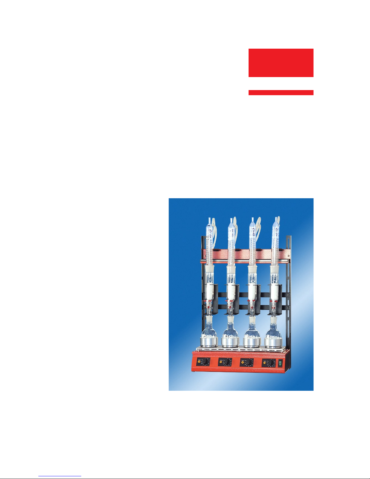
1 Description
The behrotest® In-Line Extraction Unit is used for Soxhlet extraction, mainly in food, food-
stuffs and soil analysis.
Depending on the model and conguration, the apparatus consists of either four or six
individually adjustable heating positions for round-bottom asks of up to 500 ml volume,
which are used in conjunction with extractors between 30 and 250 ml.
The full capabilities of the behrotest® In-Line Extraction Unit in daily laboratory utilization
can only be realized if you carefully read and follow all of the guidance in this manual.
Description
Vertical support bars
Drip pan
Adjustable extractor
mounts
Hot-plates with ask
adapters
In-line hot plates
Heating power ad-
justments
On/Off switch
with built-in circuit
breaker
Crossbars for the
extractor mounts
Cooling water
distributor with con-
denser stand
Heating indicator lights

– 6 –
behrotest® In-Line Extraction Unit
2 Contents of Delivery
2.1 Completeness and absence of damage
The individual components of your behrotest® In-Line Extraction Unit have been assem-
bled and packed with the greatest of care.
Please check the contents of the delivery for completeness and absence of damage be-
fore assembling the apparatus. The correct contents of delivery is presented in the follow-
ing list of components.
If you do nd damage, please follow the instructions provided in the leaet entitled
„Transportation Damage? What to do if…“,
Which you will nd included among the shipping documents. If you do have grounds for a
damage claim, please contact:
behr Labor-Technik GmbH
Spangerstraße 8
40599 Düsseldorf/Germany
Telefon: +49 (0)211 7 48 47 32
Telefax: +49 (0)211 7 48 47 48
eMail: info@behr-labor.com
2.2 List of Components
All behrotest® In-Line Extraction Units consist of a
Basic unit for four or six samples
1 In-line hot-plate array R 4 (4 hot plates) or R 6 (6 hot plates)
2 Vertical support bars
1 Cooling water distributor with condenser stand (4 or 6 place) and drip pan,
1 Crossbar with 4 or 6 adjustable extractor mounts
1 Water inow hose, polyamide, Ø 8 mm
1 Water outow hose, PVC, Ø 12 mm
1 Disconnecting tool for Speedt hose connections
1 Connection for “ pipe thread water tap
1 Adapter for “ pipe thread water tap
Depending on the model, the following complete extraction glassware is provided
R 304
4 Aluminium hotplate adapters to t 100 ml round bottom asks
4 Distance parts for 100 ml round-bottom asks
4 100 ml round bottom asks (RK 100)

– 7 –
© behr Labor-Technik 2006
4 Soxhlet extractors, 30 ml (EZ 30)
4 Spiral coil reux condensers for 30 ml Soxhlet (RFK 30)
1 Silicone tube, 6 x 2 mm, 3 m
1 Package containing 25 extraction thimbles to t the 30 ml Soxhlet extractor (EX 30 HS)
1 User’s Manual
R 306
6 Aluminium hotplate adapters to t 100 ml round bottom asks
6 Distance parts for 100 ml round-bottom asks
6 100 ml round bottom asks (RK 100)
6 Soxhlet extractors, 30 ml (EZ 30)
6 Spiral coil reux condensers for 30 ml Soxhlet (RFK 30)
1 Silicone tube, 6 x 2 mm, 3 m
1 Package containing 25 extraction thimbles to t the 30 ml Soxhlet extractor (EX 30 HS)
1 User’s Manual
R 104 S
4 Aluminium hotplate adapters to t 250 ml round bottom asks
4 Distance parts for 250 ml round-bottom asks
4 250 ml round bottom asks (RK 250)
4 Soxhlet extractors, 100 ml (EZ 100/HAHN)
4 Spiral coil reux condensers for 100 ml Soxhlet (RFK 100)
1 Silicone tube, 6 x 2 mm, 3 m
1 Package containing 25 extraction thimbles to t the 100 ml Soxhlet extractor (EX 100 HS)
1 User’s Manual
R 106 S
6 Aluminium hotplate adapters to t 250 ml round bottom asks
6 Distance parts for 250 ml round-bottom asks
6 250 ml round bottom asks (RK 250)
6 Soxhlet extractors, 100 ml (EZ 100/HAHN)
6 Spiral coil reux condensers for 100 ml Soxhlet (RFK 100)
1 Silicone tube, 6 x 2 mm, 3 m
1 Package containing 25 extraction thimbles to t the 100 ml Soxhlet extractor (EX 100 HS)
1 User’s Manual
R 254
4 Aluminium hotplate adapters to t 500 ml round bottom asks
Contents of Delivery

– 8 –
behrotest® In-Line Extraction Unit
4 Distance parts for 500 ml round-bottom asks
4 500 ml round bottom asks (RK 500)
4 Soxhlet extractors, 250 ml (EZ 250/HAHN)
4 Spiral coil reux condensers for 250 ml Soxhlet (RFK 250)
1 Silicone tube, 6 x 2 mm, 3 m
1 Package containing 25 extraction thimbles to t the 250 ml Soxhlet extractor (EX 250 HS)
1 User’s Manual
R 256
6 Aluminium hotplate adapters to t 500 ml round bottom asks
6 Distance parts for 500 ml round-bottom asks
6 500 ml round bottom asks (RK 500)
6 Soxhlet extractors, 250 ml (EZ 250/HAHN)
6 Spiral coil reux condensers for 250 ml Soxhlet (RFK 250)
1 Silicone tube, 6 x 2 mm, 3 m
1 Package containing 25 extraction thimbles to t the 250 ml Soxhlet extractor (EX 250 HS)
1 User’s Manual
optional:
Hydrolysis units – HYDRO 1 for 1 sample or HYDRO 6 for 6 samples
Circulating water coolers for condensers – UK 12/1000 or UK 12/2000

– 9 –
© behr Labor-Technik 2006
3 Assembling the
behrotest® in-line extraction units
Always operate the in-line extraction unit in a fume hood! Solvent vapors may
escape!
To avoid the risk of electrical shock, insure that no liquid comes in contact with
the power cable or gets into the inside of the apparatus!
Follow carefully safety regulations and exercise due caution in working with glass
components!
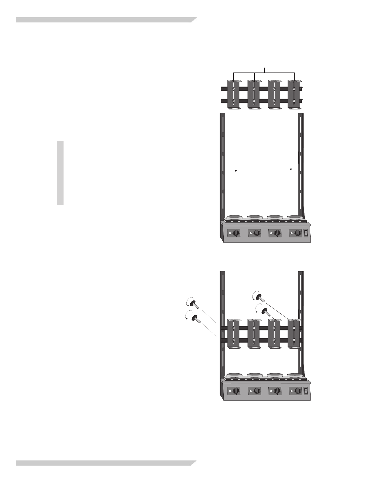
3.1 Attaching the
Vertical Support Bars
1. Place the in-line heating unit on a at level
surface.
Assembling the in-line extraction unit
2. Attach both vertical support bars to the side of
the in-line heating unit using the four knurled
screws provided.
Insure that the lower ends of the sup-
port bars, which are to be attached to the
heating unit, are resting on the bench top.
The angle bracket for attaching the sup-
port bars has elongated slots for inserting
the screws. This allows you to adjust the
vertical height of the support bars. Angle brackets
with elongated
slots
– 10 –
behrotest® In-Line Extraction Unit
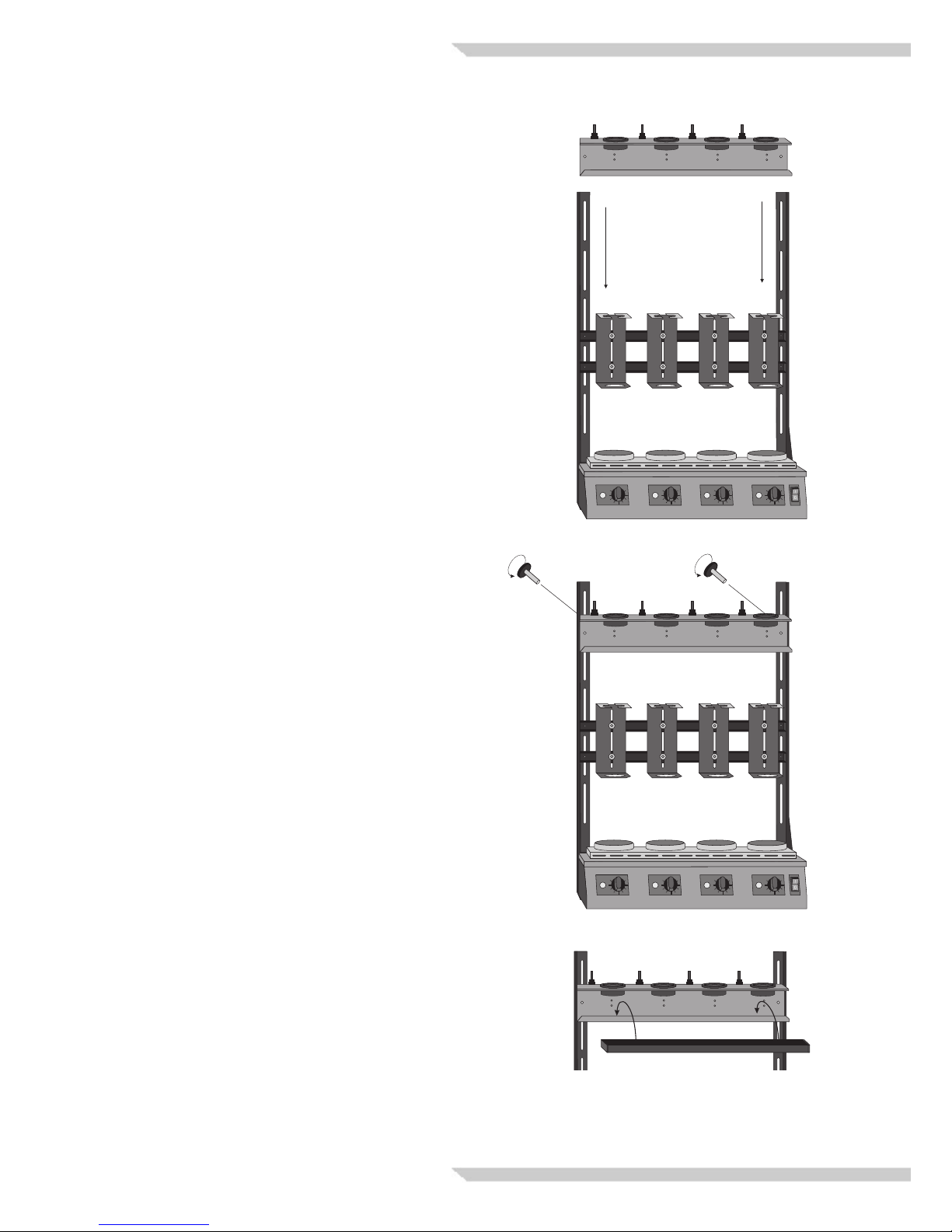
3.2 Attaching the
Horizontal Support Bars
Bars with Extractor Mountings
Insert the bars with the extractor mountings from
below between the internal track formed by the
horizontal support bars. The extractor mountings
must be oriented with the slotted opening on top,
facing forward.
The correct height of attachment for the
horizontal support bars depends on the
glassware being used. For example, in
the case of the 100 ml Soxhlet extrac-
tion, locate the screw holes of the upper
horizontal support bar at the lower ends
of the third elongated slots in the vertical
support bars. The height can be readjust-
ed as needed at any time in the future.
Fasten the horizontal support bars with the
four knurled screws provided.
Slotted openings
– 11 –
© behr Labor-Technik 2006
Condenser storage stand
with cooling water distributor
Insert the condenser storage stand from above
between the internal track formed by the horizon-
tal support bars.
Position the screw hole of the condenser stand at
the lower ends of the uppermost elongated slots
in the vertical support bars.
Fasten the condenser stand in place with
the pair of knurled screws provided.
Assembling the in-line extraction unit
Insert the drip tray into the condenser storage
stand.

– 12 –
0
l
behrotest® In-Line Extraction Unit
3.4 Inserting the glassware
To minimize the risk of breakage, always
hold all glassware in the vicinity of the
standard taper joint! Never use grease on
the standard taper joints!
1. Place the distance parts into the ask adapt-
ers.
The asks must not be placed directly
into the adapters; otherwise they might
break on heating. Never use your in-line
extraction unit without the distance parts!
2. Place the round bottom ask in the ask
adapter on the hotplate.
Check once more the height of the cross-
bars with extractor mounts. The upper
end of the neck of the round bottom ask
must protrude several millimeters into
the lower opening of the extractor mount.
This will secure the ask against tipping
over.
If necessary, adjust the height of the
crossbars.
3.3 Installing the
hot plate ask adapters
Place the hot plate ask adapters on the hot-
plates.
Take care that the adapters are seated securely
on the hot plates and cannot slip off sideways.

– 13 –
© behr Labor-Technik 2006
3. Insert the extractors from above into the ex-
tractor mounts and seat them on the round
bottom asks.
The upper horizontal segment of the extrac-
tor mounts have a slot in front. In the event
that you are using an extractor with spigot (for
example, the behrotest® EZ 100/HAHN), then
guide the extractors with the spigots carefully
through these slots.
Assembling the in-line extraction unit
4. Insert the reux condensers onto the extrac-
tors.
– 14 –
1
2
3
behrotest® In-Line Extraction Unit
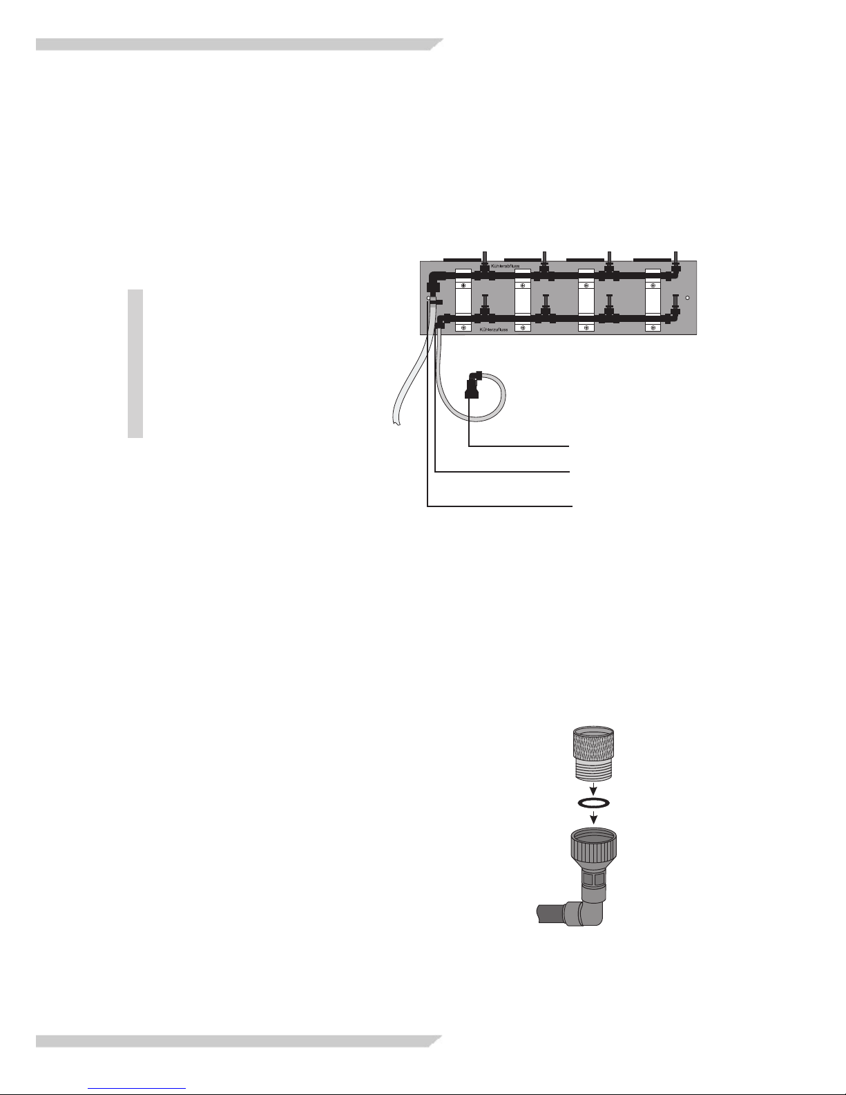
3.5 Connecting the Water Hoses
Cooling Water Distributor
1. Cooling water supply
The cooling water supply hose is made of polya-
mide and is 2 meters long. If necessary,
shorten it as required.
Use only a very sharp blade,
such as a scalpel or box cutter
to cut polyamide hoses. The cut
end must be free of burrs and at
a sharp right angle. Avoid defor-
mation of the hose. By following
these procedures a leak-free
seal will be guaranteed in the
push-on tting.
The connection (2) for the cooling water sup-
ply hose is found on the rear of the condenser
stand.
• Push one end of the water supply hose as
far as it will go into the connection.
• In the same manner, attach the “ water tap
connection (1) to the other end of the hose.
• Bring the water supply hose to a laboratory
water tap.
Water tap with “ pipe thread
Insert a washer in the connector and screw
the fasten the water supply hose to the water
tap by screwing the connector onto the “
pipe thread of the water tap.
Water tap with “ pipe thread:
Use the “ to “ adapter.
Place a washer in the connector and screw
the adapter and connector together. Then
screw the adapter onto the “ pipe thread of
the water tap.

– 15 –
© behr Labor-Technik 2006
2. Cooling water outow
The connection for the cooling water outow (3, gure on pre-
vious page) is likewise located on the rear of the cooling water
distributor with condenser stand.
Insert the black tubing segment of the outow (drain) hose as
far as it will go into the hose receptacle.
Lay the hose to a sink or other drain.
Insure that there are no tight curves or kinks in the
hose. If necessary, shorten the hose to prevent
constrictions of this nature.
3. Connections to the Condensers
• Cut appropriate lengths of the silicone tubing included in
the delivery.
The lengths of the
tubing segments
should be such as to
permit comfortable
unhindered operation
of the work station.
The segments must
not be so short that
they are under tensi-
on, nor should they
be so long that they
tangle or kink as a
result of hanging
down too far.
• Attach the silicone tubing
segments to the tubing nipples on the cooling water distri-
bution unit identied as „Kühlerabuss“ (outow) and „Kühl-
erzuuss“ (inow).
• Attach the tubing segments to the condensers.
The lower nipple on the reux condenser is for water inow.
Connect the tubing segments coming from the lower „Kühl-
wasserzuuss“ panel of the cooling water distributor to the-
se nipples. Connect the upper nipples of the condensers
in the same manner with the upper „Kühlwasserabuss“
panel of the cooling water distributor.
Assembling the in-line extraction unit

– 16 –
behrotest® In-Line Extraction Unit
Disconnecting
the quick push-in connections
If needed, the connections of the polyamide tub-
ing or the tubing nipples can easily be discon-
nected. Use the special tool provided for this
purpose.
Use the narrow slot of the tool for the nip-
ples and the inow tube and the wide slot
for the outow tube.
1. Tubing nipple quick push-in connector
• Place the tool in front of the annular rim of the
quick connector.
• With the other hand, grasp the tubing nipple.
• Press the annular rim inwards with the tool while
simultaneously pulling the tubing nipple forwards
and out of the cooling water distributor.
2. Inow/Outow Quick Connector
• Place the tool in front of the annular rim of the
quick connector of the hose.
• With the other hand, grasp the hose.
• Press the annular rim inwards with the tool
while simultaneously pulling the hose for-
wards and out of the quick connector.
3.6 Using a Model UK 12
Circulating Water Cooler
Follow carefully the instructions in the UK
12 User’s Manual.
The hose set of the circulating water cooler con-
tains an adapter for connection to the inow and
outow hoses of the cooling water distributor.
Attach the free end of the inlet hose with an
adapter. Insure that you push the end of the hose
into the connector as far as it will go. Connect the
inlet hose to the water outow outlet of the circu-
lating water cooler.
Complete the circuit by collecting the outlet hose
of the cooling water distributor to the inlet of the
circulating water cooler.
Disconnect
tubing nipple
Press
annular rim
inwards
Press annular rim inwards
Pull out hose

– 17 –
© behr Labor-Technik 2006
3.8. Connecting to the Mains
Power Line
First insure that the local mains (electrical) power
is of the same voltage as that indicated on the
model label of your behrotest® inline apparatus.
Insure that the power switch on the front of the
inline apparatus is set to „0“.
Insert the plug of the electrical power cable com-
ing from the back of the inline heating unit into a
mains power socket.
3.7 Leak Testing
You can now check the hose and tubing connec-
tions for leaks.
Turn on the water tap and make any necessary
changes to the hose and tubing connections.
Assembling the in-line extraction unit

– 18 –
behrotest® In-Line Extraction Unit
4 Using the inline
extraction unit
Always use the in line extraction unit in a
fume hood!. Escape of solvent vapor is
possible!
Before inserting the round-bottom asks
always make sure the distance parts
are laid out properly and smoothly in the
ask adapters. Never use your inline
extraction unit without the distance parts.
If the asks are inserted without the
distance parts directly into the adapters
they might break on heating - danger of
re or explosion!
To avoid risk of electrical shock, insure
that no liquids come in contact with the
power cable or get into the apparatus
housing!
Employ due care in working with chemi-
cals and follow the precautions cited in
the Material Safety Data Sheets!
Employ due care in working with glass
components!
Never touch the solvent vessel with your
bare hands immediately after an extrac-
tion; it will be very hot and painful burns
may result!
To avoid risk of re or explosion, avoid
spilling solvent under any circumstances
on the hot heating elements!
– 19 –
© behr Labor-Technik 2006
1 2 3
4.1 Sample preparation
Prepare the sample for extraction.
Place the sample material into the extrac-
tion thimble. Close the top of the thimble
with fat-free cotton wool and insert the
closed thimble into the extractor.
Insert the extractor into the extractor
mounting (1).
Make sure the distance parts are laid out
properly and smoothly in the ask adapters.
Now ll solvent into the round bottom
ask. Place the ask on the hotplate ask
adapter (2) and insert the extractor into the
mouth of the ask (3).
Attach the reux condenser to the extractor
and start the ow of cooling water.
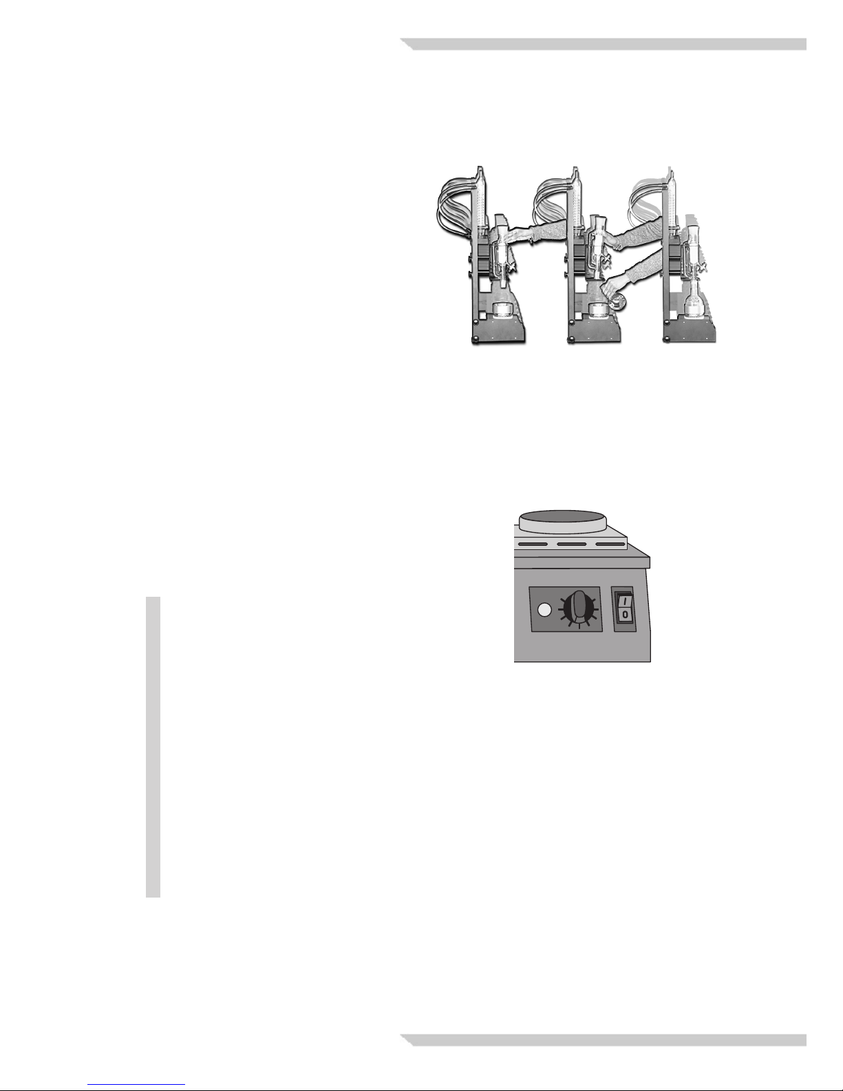
4.2 Switching the inline
heating unit on
Turn the power switch on the front of the
inline heating unit to the „I“ position.
The power switch of the behro-
test® inline heating unit fullls
two functions. It serves to turn
the apparatus on and off and also
contains a built in electrical circuit-
breaker.
The circuit-breaker operates simi-
larly to those in household appli-
ances – it shuts off the electrical
power supply.
Since this safety feature (circuit-
breaker) requires cocking a spring,
turning the power switch of the in-
line heating unit to the on position
will require somewhat more force
than a simple on/off switch.
Using the inline extraction unit

– 20 –
behrotest® In-Line Extraction Unit
4.3 Starting the Extraction
Adjust the heat level for the individual sample po-
sitions with the power level knobs.
Adjust the power levels so that the solvent boils
uniformly in all positions and condenses in suf-
cient amounts to uniformly extract all of the
samples.
The yellow „HEATING“ indicator lamps of each
heating position indicate heating activity.
4.4 Ending the Extraction
After the solvent has been all evaporated or
separated, turn the power level knobs down and
switch the inline heating unit off with the MAIN
SWITCH.
This manual suits for next models
5
Table of contents


