Servomex DF-150E User manual

Oxygen Analyzer
DF
-
150
E
OPERATOR MANUAL

Copyright 2011 by Servomex Corporation
No part of this publication may be reproduced, stored in a retrieval system or transmitted in any form, or by
any means including electronic, mechanical, photocopying, recording or otherwise without prior written
permission of Servomex Corporation.
Stab-Eland Bi-Strataare trademarks of Servomex Corporation.

DF-150E Operator Manual
Version 101711
Your Process Oxygen Analyzer has been designed, manufactured and is supported under
ISO-9001 controls, thus helping to insure the highest possible standards of quality.
Every analyzer that Servomex manufactures is tested and operated on a variety of gas
concentrations to insure that it functions properly when you receive it.
The certificate of calibration assures your analyzer has been calibrated on gases that are
traceable to NIST standards. With proper maintenance, your analyzer should remain
calibrated for years.
For a fast and successful startup, please read this manual carefully. There are important
cautions and a number of helpful hints to help you to optimize the operation of your analyzer.
For more information or if you have questions, please do not hesitate to go to our website at
Servomex.com, or contact your local Servomex Business Center as found on the back cover
of this manual.

Read Me First…
Unpacking -
Follow the steps below to unpack your Servomex analyzer.
1. Examine the condition of the packaging and its contents. If any damage is apparent,
immediately notify the carrier and Servomex. Do not proceed with the installation.
2. Check the contents against the packing slip to make sure the shipment is complete.
Unattached equipment may be shipped with the analyzer in supplemental packaging.
Shortages should be reported to Servomex immediately.
All analyzers are shipped with the following:
Item Servomex Part Number
One bottle of Hummingbird Brand E-lectrolyte Blue Electrolyte Blue
One bottle of Hummingbird Brand
Replenishment Solution
210515
Power cord with 115 VAC connector
NOTE: No power cord is supplied with 220 VAC units.
210408
Operator Manual 211600
3. Open the analyzer door, remove any shipping materials, and verify that nothing has come
loose during transit.
4. The analyzer is set at the factory to operate on 115 VAC or 220 VAC. Locate the
voltage indicator on the rear panel beside the AC power input and verify the voltage is set
as ordered

Table of Contents DF-150E 1
1 Table of Contents
1Table of Contents .................................................................... 1
2Table of Figures....................................................................... 3
3CAUTIONS ................................................................................ 4
3.1 Explanation of Graphic Symbols.............................................................................4
3.2 Important Warnings................................................................................................5
4Specifications .......................................................................... 7
5Analyzer Start-Up Procedure ................................................ 11
5.1 Charging the Sensor .............................................................................................12
5.1.1 Remove the Sensor...................................................................................12
5.1.2 Add Electrolyte........................................................................................13
5.1.3 Re-install the Sensor ................................................................................13
5.2 Making Sample Gas Connections..........................................................................13
5.2.1 Gas Connection........................................................................................14
5.3 Making Output Signal Connections ......................................................................14
5.4 Powering Up the Analyzer ....................................................................................15
5.5 Additional Capabilities .........................................................................................16
6Standard Features .................................................................17
6.1 Stable Calibration .................................................................................................17
6.2 Electrolyte Condition Indicator .............................................................................17
6.3 Analog Output ......................................................................................................18
7Options ................................................................................... 19
7.1 Stab-El..............................................................................................................19
7.2 Alarms..................................................................................................................20
7.2.1 Adjusting Oxygen Alarm Set Points.........................................................20
7.2.2 Alarm Relays...........................................................................................20
7.3 Pressure Regulators...............................................................................................21
7.4 Filter.....................................................................................................................22
7.5 Low Flow Indication .............................................................................................23
7.6 Low Flow Alarm...................................................................................................23
7.6.1 Low Flow -Sensor Off.............................................................................23
7.7 Flow Control Valve...............................................................................................24
7.8 Stainless Steel Outlet Tubing ................................................................................24
7.9 Pump ....................................................................................................................24
7.9.1 Pump Control ..........................................................................................25
7.10 Isolated 4 to 20 mA Output .................................................................................25
7.11 Gas Scale Correction Factor ................................................................................25
7.11.1 Adjusting the Gas Scale Factor Pot for Light Gases (He or H2).............26
7.11.2 Adjusting the Gas Scale Factor Pot for Gases Heavier Than Nitrogen...28
7.12 Panel Mount........................................................................................................30
7.13 Rack Mount.........................................................................................................31
7.14 Remote Sensor Installations.................................................................................32
7.14.1 Sensor on Remote Bracket with Optional Pump....................................32

2 DF-150E Table of Contents
7.14.2 Sensor in NEMA 7 Enclosure.............................................................. 33
7.14.3 Sensor in NEMA 4 Enclosure.............................................................. 35
7.14.4 Temperature Control in R4/R7 Enclosures........................................... 36
8Sample Gas and Plumbing Cautions ................................... 37
8.1 Normal Operating Conditions............................................................................... 37
8.2 Condensation/ Liquid Slugs.................................................................................. 37
8.3 Temperature......................................................................................................... 38
8.4 Leaks.................................................................................................................... 38
8.5 Process Up-sets (Oxygen Shock)........................................................................... 38
8.6 Reactivity with KOH Electrolyte........................................................................... 39
9Outputs and Remote Connections....................................... 41
9.1 The I/O Connector................................................................................................ 42
9.1.1 Alarm 1 and 2 (NC-C-NO)...................................................................... 42
9.1.2 4 to 20 mA Isolated Output (4-20+, 4-20-)............................................... 43
9.1.3 Analog Output (Rec + & Rec - ) .............................................................. 43
9.1.4 Remote Range Indicator (Range Com -Range 1, 2, 3)............................. 43
9.1.5 Sensor Off (Sensor Off Com, Sensor Off) ................................................ 44
9.1.6 DC Common (DC Com).......................................................................... 44
9.1.7 Ground ( )............................................................................................. 44
9.2 The Remote Sensor Connector.............................................................................. 44
9.2.1 Remote Sensor (Sensor +, Sensor -)......................................................... 44
9.2.2 Secondary Electrodes (Sec El +, Sec El -) ................................................ 45
9.2.3 A, B (A, B).............................................................................................. 45
9.2.4 Flow Switch (Flow SW, Flow SW Com).................................................. 45
9.3 Pump Control Connector ...................................................................................... 45
9.3.1 Pump Control.......................................................................................... 45
9.3.2 Analyzer Control of a Remote Pump........................................................ 46
9.3.3 Remote Control of the On-board Pump .................................................... 46
10 Maintenance and Calibration Checks .................................. 47
10.1 Sensor Maintenance............................................................................................ 47
10.1.1 Restoring electrolyte level.................................................................... 47
10.2 Calibration.......................................................................................................... 48
10.2.1 Adjusting Calibration .......................................................................... 48
10.2.2 Adjusting Calibration (with the Gas Scale Factor Option installed)...... 49
10.3 Cleaning the Analyzer ........................................................................................ 50
11 Theory of Operation .............................................................. 51
12 Troubleshooting .................................................................... 53
12.1 Troubleshooting Guide........................................................................................ 53
12.1.1 Problem Observations .......................................................................... 53
12.1.2 Remedy Table...................................................................................... 54
12.2 Troubleshooting Considerations.......................................................................... 55
12.2.1 Gas Pressure Effects............................................................................. 55
12.2.2 Positive Pressure Operation.................................................................. 55
12.2.3 Negative Pressure Operation ................................................................ 55
12.2.4 Temperature Effects on Sensor Performance........................................ 56
12.2.5 Flow Rate Effects on Sensor Performance ............................................ 56
12.3 Replaceable Parts................................................................................................ 57
12.4 Fuse Replacement ............................................................................................... 58
13 Shipping the Analyzer........................................................... 59

Table of Figures DF-150E 3
13.1 Draining the Sensor ............................................................................................59
14 Safety and Operating Notices............................................... 61
14.1 Safety Notices......................................................................................................61
14.2 Operating Notices................................................................................................61
14.3 Material Safety Data Sheet -Electrolyte ..............................................................71
14.4 Material Safety Data Sheet –Replenishment Solution .........................................76
15 Warranty ................................................................................. 79
16 Index ....................................................................................... 81
2Table of Figures
Figure 1: DF Series Oxygen Analyzer.............................................................. 9
Figure 2: Major Internal Components............................................................ 12
Figure 3: Quick Disconnect........................................................................... 13
Figure 4: Sensor Off Switch.......................................................................... 15
Figure 5: Power Switch................................................................................. 16
Figure 6: Electrolyte Condition Indicator ...................................................... 17
Figure 7: Analog Output Setting ................................................................... 18
Figure 8: Setting alarms ................................................................................ 20
Figure 9: Regulator Installation..................................................................... 21
Figure 10: Filter Installation .......................................................................... 22
Figure 11: Combination Filter/Regulator Installation ..................................... 23
Figure 12: Low Flow Alarm.......................................................................... 24
Figure 13: Gas Correction Factor Adjustment ............................................... 28
Figure 14: Panel Mount Dimensions and Layout ........................................... 30
Figure 15: Panel Mount Cut-out Dimensions................................................. 30
Figure 16: Rack Mount Dimensions and Layout............................................ 31
Figure 17: Double Rack Mount Dimensions and Layout................................ 31
Figure 18: Remote Sensor Bracket and Wiring Pin-out.................................. 32
Figure 19: Remote Sensor Bracket Mounting Holes...................................... 33
Figure 20: NEMA 7 Remote Sensor Enclosure and Wiring Pin-out ............... 33
Figure 21: NEMA 7 Enclosure Mounting Detail............................................ 34
Figure 22: NEMA 4 Remote Sensor Enclosure and Wiring Pin-out ............... 35
Figure 23: NEMA 7 Enclosure Temperature Control .................................... 36
Figure 24: Rear Panel Connections................................................................ 41
Figure 25: I/O Connector Pin-out.................................................................. 42
Figure 26: Remote Sensor Connector Pin-out ............................................... 44
Figure 27: Pump Control Connector ............................................................. 45
Figure 28: Calibration Controls ..................................................................... 49
Figure 29: Calibration Adjustment with GSF installed ................................... 50
Figure 30: Schematic of DF Series Oxygen Sensor........................................ 51

4 DF-150E CAUTIONS
3 CAUTIONS
There are a number of warnings and cautions that must be observed to avoid
damage to the analyzer as well as insuring the safety of its users. The analyzer
must be operated in a manner specified in this manual. Servomex cannot be
responsible for direct or consequential damages that result from installing
and/or operating the analyzer in a manner not described in this manual.
Importantly, the analyzer has been designed for use with inert, non-toxic, non-
combustible sample gases only. Servomexcannot be responsible for direct or
consequential damages that result from using the analyzer with these gases.
3.1 Explanation of Graphic Symbols
Following is a list of the various symbols used throughout this manual and their
definitions.
CAUTION
This symbol alerts the user to the presence of physically hazardous
conditions that may be dangerous to individuals or equipment.
NOTE
This symbol alerts the user to the presence of important
operations and/or maintenance information.
This symbol alerts the user to the presence of caustic liquid. Refer
to the MSDS at the back of the manual for handling instructions.

CAUTIONS DF-150E 5
3.2 Important Warnings
DANGER
Potentially hazardous AC voltages are present within this
instrument. Leave all servicing to qualified personnel.
Disconnect the AC power source when installing or removing:
external connections, the sensor, the electronics, or when
charging or draining electrolyte.
CAUTION
Do not set-up or operate this Oxygen Analyzer without a
complete understanding of the instructions in this manual. Do not
connect this Analyzer to a power source until all signal and
plumbing connections are made.
CAUTION
This analyzer must be operated in a manner consistent with its
intended use and as specified in this manual.


Specifications DF-150E 7
4Specifications
Range
DF-130E Single Range Analyzer
Range (ppm) DF 130E
Model #
Range (%)DF-130E
Model #
0 to 5,000 ppm 131-5000 0 to 25% 131-P25
0 to 1,000 ppm 131-1000 0 to 10% 131-P10
0 to 500 ppm 131-500 0 to 5% 131-P5
0 to 100 ppm 131-100 0 to 1% 131-P1
0 to 50 ppm 131-50
0 to 10 ppm 131-10
DF-150ESingle Range Analyzer
Range (ppm) DF-150E
Model #
Range (%)DF-150E
Model #
0 to 5,000 ppm151-5000 0 to 25% 151-P25
0 to 1,000 ppm 151-1000 0 to 10% 151-P10
0 to 500 ppm 151-500 0 to 5% 151-P5
0 to 100 ppm 151-100 0 to 1% 151-P1
0 to 50 ppm 151-50
0 to 10 ppm 151-10
DF-150EThree Range Analyzer
Ranges (ppm) DF-150E
Model #
Ranges (%)DF-150E
Model #
0 to100/1,000/10,000 ppm 153-10000 0 to 0.25/2.5/25% 153-P25
0 to 50/500/5,000 ppm 153-5000 0 to 0.1/1/10% 153-P10
0 to 10/100/1,000 ppm 153-1000 0 to 0.05/0.5/5% 153-P5
0 to 5/50/500 ppm 153-500
0 to 1/10/100 ppm 153-100

8 DF-150E Specifications
Response Time
Responds instantaneously to O2change. Equilibrium time depends on specific
conditions. Typically less than 10 seconds to read 90% of a step change.
Accuracy
At constant conditions, the greater of +/-3% of reading or 0.5% of
measurement range, but not lower than 0.05% of full analyzer range for three
range analyzers.
Sample Gas Compatibility
Standard Sensor
All inert and passive gases including N2, H2, CO, freons, light hydrocarbons,
etc.
Sensor with Stab-El
Neutralizes contaminants including acids such as CO2, H2S, Cl2, NOX, SOX,
etc. (See page 19 for concentration limits).
Sample Requirements
Gas phase, non-condensing, sample temperature: -17 to 66°C (0 to 150°F).
Flow rate 1.0 to 2.0 scfh at 0.2 to 1.0 psig pressure.
Ambient Temperature Requirements
Room/cabinet temperature: 0 to 50°C (32 to 120°F)
Physical Dimensions
Overall Dimensions: 20.3cm w X 21.6cm h X 27.9cm d
Weight: 6 kg
Overall Dimensions: 8.0”w X 8.5”h X 11”d
Weight: 15 lbs
Miscellaneous
Store and operate between 0°C and 45°C (32°F and 112°F).
100-120/200-240 VAC, 50-60Hz, 1.0/0.5A maximum.
Nominal power consumption:20 Watts
ETLc Approved

Specifications DF-150E 9
Figure 1: DF Series Oxygen Analyzer


Analyzer Start-Up Procedure DF-150E 11
5Analyzer Start-Up Procedure
Your analyzer has been thoroughly tested and calibrated however, it is
necessary to make proper gas connections and to “charge” the sensor prior to
turning the analyzer on.
Analyzer start-up requires the following procedures:
A. Charging the Sensor
B. Making Sample Gas Connections
C. Making Output Signal Connections
D. Powering up the Analyzer
CAUTION
To avoid damage to your analyzer:
Do not operate without electrolyte
Do not use more than one bottle of E-Lectrolyte Blue
Do not operate without gas flow
Do not operate a trace level analyzer for more than a few
minutes while exposed to air.
Do not exceed the pressure and flow limits
The electrolyte is a caustic solution. Review the Material
Safety Data Sheet (MSDS) on page 71 before handling the
electrolyte solution.

12 DF-150E Analyzer Start-Up Procedure
5.1 Charging the Sensor
For sensors mounted remotely skip directly to the section on Adding
Electrolyte on page 13.
5.1.1 Remove the Sensor
1. Open the front door.
2. Turn power off.
3. Disconnect the electrical cable that runs to the sensor.
4. Loosen the two, knurled thumb screws in front of the sensor.
5. Remove the bulkhead nut from the inlet gas connection on the rear of the
analyzer.
6. If the analyzer is equipped with the stainless steel outlet tubing option,
remove the nut from the outlet bulkhead fitting.
7. Carefully slide the sensor out of the analyzer a few inches.
8. Remove the quick disconnect at the top of the flowmeter. (Skip this step if
the analyzer is equipped with the stainless steel outlet tubing option.)
9. Finish sliding the sensor out of the cabinet.
CAUTION
REMOVE SENSOR WHEN CHARGING OR CHANGING -LECTROLYTE.
RE-FILL LIQUID LEVEL WITH DELTA F REPLENISHMENT SOLUTION
ONLY, NOT -LECTROLYTE. AVOID SPLASHING AND DRIPPING.
KEEP ANALYZER IN VERTICAL POSITION WHEN FILLED WITH
-LECTROLYTE.
REPLENISHMENT SOLUTION MAY BE ADDED WHILE ANALYZER IS
ON-LINE.
E
E
E
Figure 2: Major Internal Components

Analyzer Start-Up Procedure DF-150E 13
PUSH
ROTATE
PULL
ROTATE
Figure 3: Quick Disconnect
5.1.2 Add Electrolyte
1. Un-screw the lid from the sensor.
2. Add the entire contents of one bottle of Hummingbird Brand E-Lectrolyte
Blue to the sensor.
3. Replace the lid securely.
5.1.3 Re-install the Sensor
1. Attach the quick disconnect at the top of the flowmeter. (Skip this step if
the analyzer is equipped with the stainless steel outlet tubing option.)
2. Carefully slide the sensor into the analyzer.
3. Tighten the thumbscrews.
4. Re-connect the electrical cable to the sensor.
5. Replace the bulkhead nut on the inlet gas connection on the rear of the
analyzer. NOTE: After seating the nut finger tight, use a wrench to turn it
only an additional 10 degrees. Do not over tighten the bulkhead nut.
6. If the analyzer is equipped with the stainless steel outlet tubing option,
replace the nut on the outlet bulkhead fitting.
7. Allow the sensor to sit for 60 minutes before starting gas flow.
5.2 Making Sample Gas Connections
NOTE
For gas pressures between 1.0 and 5.0 psig use a high quality flow
control valve between the gas source and the analyzer to set the
flow rate.
You may have an optional Flow Control Valve mounted on the
sensor bracket and accessible behind the door (see “Flow Control
Valve” on page 24).
For gas pressures above 5 psig use a high quality pressure

14 DF-150E Analyzer Start-Up Procedure
regulator to set the flow rate.
NOTE
For best results, after putting electrolyte in the sensor, allow the
sensor to sit for 60 minutes before starting gas flow.
5.2.1 Gas Connection
1. Connect the gas line to the 1/8inch compression fitting marked sample inlet
on the rear of the analyzer.
2. Open the door and slowly adjust the flow rate to 1.0 scfh as indicated on
the flowmeter using the flow control valve or pressure regulator. Do not
control the flow with the valve mounted in the flowmeter on positive
pressure installations.
3. If you are using a gas other than nitrogen, you must set the “indicated”
flow rate as shown in Table 1.
Background Gas Flowmeter Setting (scfh)
Argon 1.2
Ethylene 1.0
Nitrogen or Air 1.0
Carbon Monoxide 1.0
Methane 0.8
Hydrogen 0.3
Helium 0.4
Table 1: Flowmeter Settings versus Background Gas
NOTE
Unless otherwise requested, the analyzer is factory calibrated on
nitrogen. Analyzer readings will be inaccurate if used with a
background gas other than the one for which it is calibrated. If the
analyzer was calibrated on a gas other than nitrogen, the gas will
be noted on the calibration log inside the front door and on a label
below the display.
5.3 Making Output Signal Connections
The following considerations are important when performing this step:
The analog output signal is factory-set to 0 to 10 VDC unless otherwise
specified.

Analyzer Start-Up Procedure DF-150E 15
The analog output is proportional to the oxygen reading of the instrument.
If you have a Three Range Analyzer the output will be scaled to the
“selected” range.
The minimum impedance of the load is 10K Ohm.
5.4 Powering Up the Analyzer
1. Verify the analyzer is set to the desired 110 VAC or 220 VAC selection by
checking the voltage indication on the rear panel. NOTE: A power cord is
not included with analyzers ordered for 220 VAC operation. The power is
supplied through a standard IEC 60320 C13 connector.
2. For concentrations below 100 ppm, it is useful to let the analyzer “purge”
by letting gas flow through it for about five minutes before the power and
sensor are turned on.
3. A three range analyzer should be set to the highest concentration range.
4. Be sure the Sensor Off switch is not pushed in (OFF). See Figure 4
5. Turn the analyzer on using the power switch. See Figure 5
6. Allow several minutes for the analyzer to come “on range”.
7. Progressively switch to a lower range as the reading allows.
Figure 4: Sensor Off Switch

16 DF-150E Analyzer Start-Up Procedure
Figure 5: Power Switch
5.5 Additional Capabilities
Your analyzer may be equipped with additional capabilities. Consult the
Standard Features section on page 17 and the Options section on page 19 for
information regarding:
Analog Output Scaling for 0 to 1.0, 2.0 or 5.0 VDC
4 to 20 mA Output
Stab-ElAcid Gas System
Pressure Regulators and Flow Valves
Gas Flow Switch
Sample Pump
Gas Scale Factor
Also, see the Outputs and Remote Connections section on page 41 for
information regarding:
CE Qualified Analyzer Outputs
Remote Sensor Operation
Remote Pump Operation
Remote Control of On-board Pump
This manual suits for next models
1
Table of contents
Other Servomex Analytical Instrument manuals
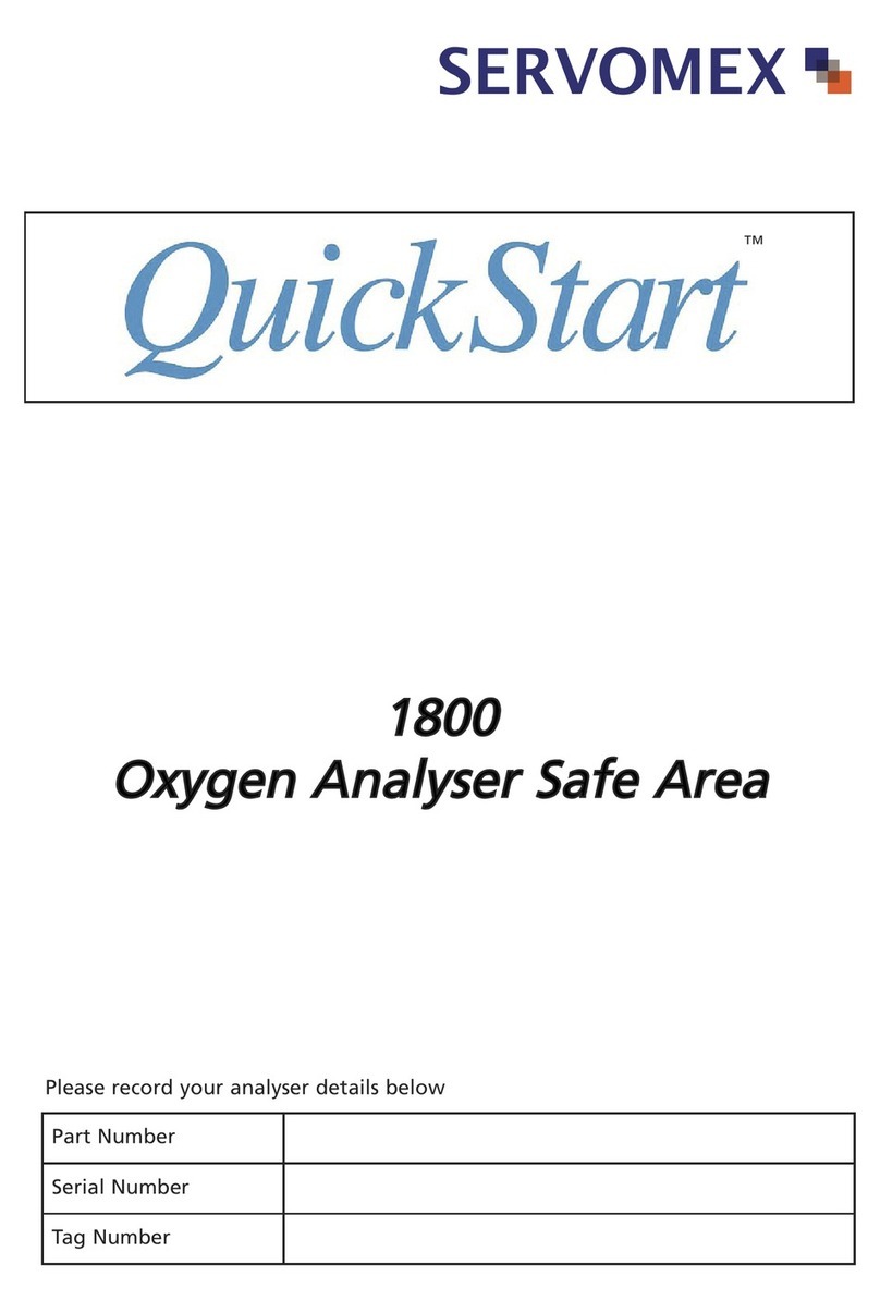
Servomex
Servomex xendos 1800 Series User manual
Servomex
Servomex DF-310E User manual

Servomex
Servomex 700B User manual
Servomex
Servomex SERVOPRO k2001 User manual
Servomex
Servomex SERVOTOUGH SpectraExact 2500 Instruction manual
Servomex
Servomex SERVOPRO 4900 User manual
Servomex
Servomex NanoTrace DF-760E User manual
Servomex
Servomex SERVOPRO Chroma User manual
Servomex
Servomex 2700 User manual
