Beiyuan BQS-1H User manual

Page 1of 17
Instruction Manual
For
e-Shear Mace Electric Handpiece <BQS-1(H)>
Xinjiang Beiyuan-Tyree Mechanical Engineering Co. Ltd

Page 2of 17
Contents
II. Overview...............................................................................................................3
2.1 Product features................................................................................................3
2.2 Technical parameters........................................................................................3
III. Installation ...........................................................................................................4
3.1 Installing combs and cutters..............................................................................4
3.2 Comb selection.................................................................................................5
3.3 Chickenfeet.......................................................................................................5
3.4 Remove and replace the fork body assembly and the roller .............................6
3.6 Adjusting tension...............................................................................................7
IV. Operation.............................................................................................................8
4.1 Pre-work inspection and preparation ................................................................8
4.2 Pre-use and in-use safety and precautions.......................................................8
4.3 Using the handpiece.........................................................................................8
V. Maintenance and Repair....................................................................................11
5.1 Regular checks...............................................................................................11
5.2 Repair and maintenance.................................................................................12
Troubleshooting Guide..........................................................................................13

Page 3of 17
1. Please read this manual carefully before operating.
Thank you for choosing BEIYUAN e-Shear Mace electric handpiece, we hope you
will find full satisfaction with its shearing performance. Although every individual
handpiece is rigorously tested before leaving our factory, in order to ensure safety
during operation, and to maintain good working condition and extend its service life,
please read this manual carefully before use.
II. Overview
2.1 Product features
The e-Shear Mace BQS-1(H) electric handpiece consists of the electric handpiece
assembly and handpiece power supply. Its main features are:
1. a 48V DC power supply with power saving provides 2 speeds 2900 and
3200rpm.
2. ergonomically designed barrel for more comfort and flexibility during
operation.
3. smooth running, low vibration and low noise.
4. small size, light weight, compact, easy to operation, easy to carry.
5. driven by a powerful and durable brushless electric motor, it is suitable for
general and professional shearing.
2.2 Technical parameters
Item
Parameter
Supply voltage
90 –260 V AC
Output voltage
48 V DC
Motor power output
350 W
Cutting speed
2900/3200rpm
Page 4of 17
III. Installation
3.1 Installing combs and cutters
3.1.1 Combs
Place the comb on the cutting head of the handpiece, make sure the comb and the
cutting head is properly aligned and symmetrical. At this stage do not tighten the
comb screw, apply limited pressure just enough to hold the comb in place.
3.1.2 Cutters
Insert cutter then tighten the tension nut, until the tips of the chickenfeet fit firmly into
the two holes on both sides of the cutter.
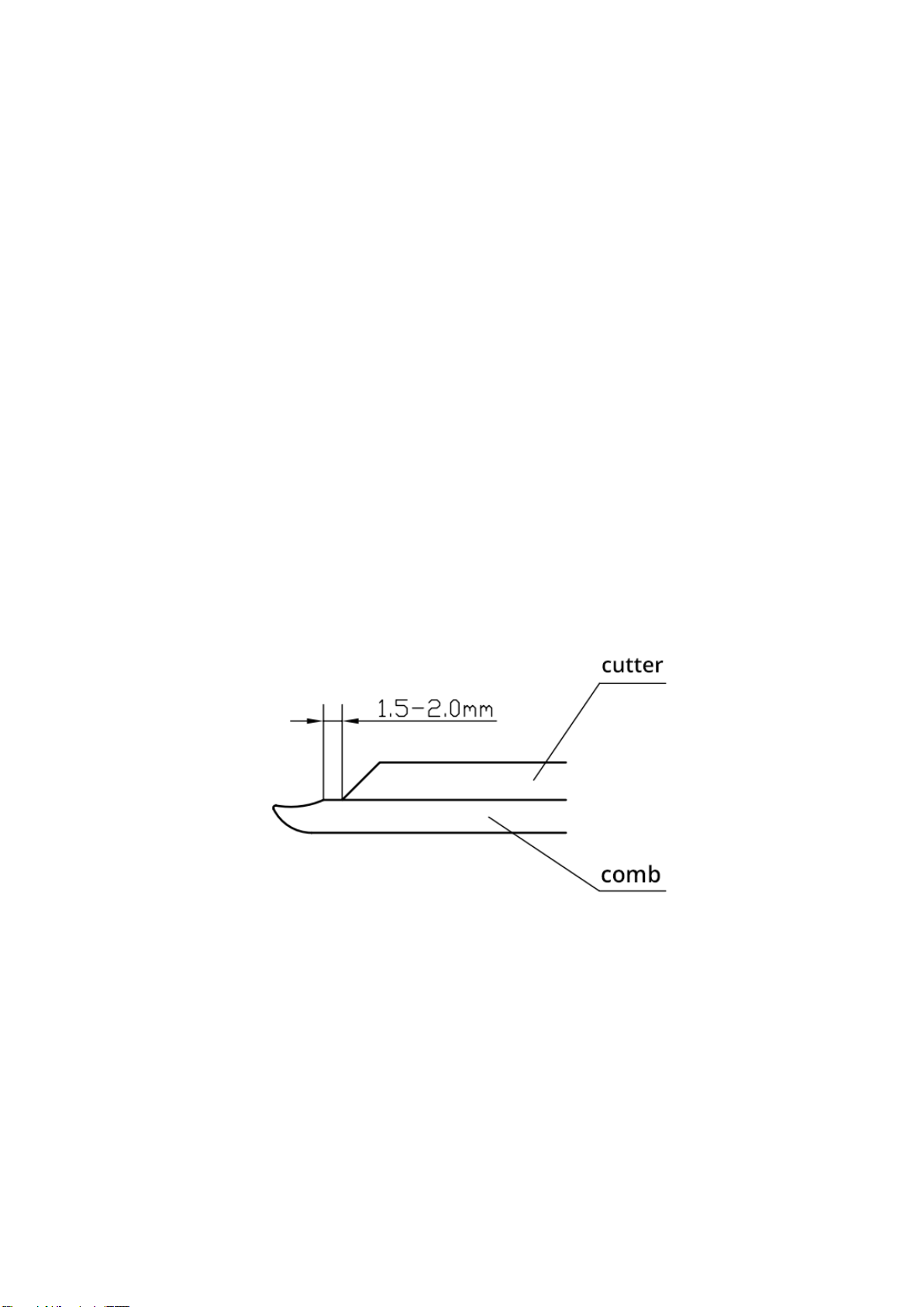
3.1.3 Adjusting and securing comb
Adjust the relative positions of the comb and cutter, ensure the point at which the
bevel of the comb begins is 1.5 to 2 mm from the tip of the middle tooth of the cutter
(see fig.1). Also ensure that the comb and cutter is symmetrically positioned, then
secure the comb firmly using the provided spanner.
Fig. 1

Page 5of 17
3.2 Comb selection
Choosing the right comb for the job is a vital part of preparation for shearing.
Selection of comb should consider shape of the tip, bevel and width. (see fig. 2)
Fig. 2
In general:
•Short bevel is principally used when shearing is at its best and the stock are in
top condition.
•Medium bevel is the most widely used comb and suitable for the majority of
crossbred shearing.
•Long bevel is particularly suitable for fine wool sheep when the wool is dense
and sticky.
Width selection should take into account the user’s level of experience with shearing.
For more information on comb and cutter selection, please visit:
www.beiyuanshearing.com.au
3.3 Chickenfeet
Before mounting chickenfeet, apply a small amount of grease to the two mounting
holes on the forkbody, then insert the left and right chickenfeet into the left and right
holes respectively, make sure the safety spring falls into the groove of the
chickenfeet.
To take out the chickenfeet, twist the chickenfeet 180° then pull outward.
The chickenfeet is secured onto the forkbody by a safety spring, ensure the screw
holding the safety spring in place is not loose.

Page 6of 17
3.4 Remove and replace the fork body assembly and the roller
3.4.1 Method of removal
The fork body assembly can be removed without removing the center post.
First unscrew the tension nut, then remove the tension pin and tension sleeve.
Remove the safety screw behind the tension nut and remove the fork body with the
roller attached.
3.4.2 Replacing fork body
Remove the oil hole cap on the top of the handpiece. Place a small amount of
grease onto the roller (ball) and ball race of the fork body. Place the ball onto the
crankshaft using a pen, screwdriver or other suitable method (make sure that the flat
side of the roller is facing the crank spindle). Place the crank and roller in the bottom
position in the handpiece. Insert the fork body from the front of the handpiece and
over the ball. After it is confirmed that the center post cup is sitting onto the center
post correctly, replace and tighten the safety screw.
3.5 Adjusting center post
The center post has been adjusted to the correct position when leaving the factory, it
can suit cutters of different thicknesses. Do not re-adjust the center post unless
necessary.
If adjustment is necessary, first, use a worn cutter (approx.. 3.5mm in thickness), and
a comb of any thickness, set the comb in place (see adjusting and securing comb
above), then adjust the roller on the crank spindle to the highest position.
3.5.1 Adjusting roller to the highest position
(1) first remove the cover cap on top of the handpiece, check to see if the roller is
positioned at the top of the groove of the fork body. If its position is at the top, go to
step (3).
(2) If the roller is not positioned at the top of the groove on the fork body, then start
and stop the handpiece, until the roller is positioned at the top of the groove.
Caution: before starting the machine, ensure the comb and cutter are fitted
and tension applied.
(3) With the roller positioned at the top, turn off the power supply, disconnect the
cord between the handpiece and power supply.
Caution: before carrying out repair work, ensure power is disconnected!
(4) Loosen tension, hold the front of the fork body and move horizontally back and
forth, until the roller is at its highest position. (Note: use care when adjusting the

Page 7of 17
forkbody, excessive movement may cause the roller to slide down, if this happens,
repeat step (2).
3.5.2 Adjusting center post
Loosen the center post nut and insert the post gauge as per illustration, keeping it at
90 degrees to the handpiece. Turn the center post until the center of the gauge is
level with the gauge top. Retighten the center post nut (Fig).
Fig.3
3.6 Adjusting tension
3.6.1 Installing tension retaining spring
When installing, first make sure that the larger curved tip of the spring points to the
clockwise direction (viewed from the top) as it is inserted into the thread bush, then
insert the smaller curved tip into the small hole. Apply force to press the retaining
spring into the grooves of the thread bush.
Caution: not installing the tension retaining spring could cause loss of tension
capacity, resulting in damage to the handpiece!
3.6.2 Tension problems
Be aware that the size of each end of the tensioning pin is different, ensure the
larger end sits in the tension pin cup. Also ensure that the downward tips of the
chickenfeet are pressed firmly into the holes on the cutter. To apply tension,
smoothly rotate and tighten the tension nut. Do not apply too much pressure as it
may cause overheating and accelerate blade wear. When cutting is not smooth, first
check the sharpness of the blades.
Caution: the downward tips of the chickenfeet must be pressed firmly into the
holes on the cutter, otherwise tension cannot be applied properly.

Page 8of 17
IV. Operation
4.1 Pre-work inspection and preparation
(1) Check that the comb and cutter are properly installed, and tension is correct.
(2) Check if the gearbox has been greased as required, other lubricated parts have
been greased as required.
(3) Check if the voltage of the main power supply and the special power supply
(Controller) for the handpiece is correct.
4.2 Pre-use and in-use safety and precautions
(1) The power outlet must be reliably grounded.
(2) Before turning on the power, the switche on the handpiece must be set to OFF.
(3) After the power is connected, with the handpiece in hand, turn on the switch at
the back of the handpiece.
(4) During shearing, the cutting head of the handpiece should always maintain a safe
distance from the operator.
(5) During shearing, the lead of the handpiece should be kept free and unobstructed
to avoid tangling with sheep.
(6) While on break, the handpiece should be turned off to prolong its service life.
(7) Keep the vents of the handpiece motor free from blockage, any wool or debris
blocking the vents should be promptly removed.
(8) If a problem occurs during shearing, first shut off the handpiece and cut off the
power supply, then proceed to perform inspection and maintenance.
(9) Ensure the handpiece is turned off and the power is cut off before loosening the
tension nut.
(10) Do not turn on the handpiece without first installing the comb and cutter.
Caution: power must be completely unplugged before performing maintenance
on the handpiece!
4.3 Using the handpiece
(1) Plug in the power cord into the power supply and ensure it is secure.
(2) Hang or fix the control box at a height of approximately 1.4 –1.7 meters above
ground.
(3) Connect the control box to the main power supply with its 3 points plug.
(4) To start or halt operation, use the switch located at the back of the handpiece.
Caution: the handpiece must be started under zero load before every
operation.

Page 9of 17
Caution: in the event that an emergency stop is required ( e.g. sheep tangling),
press the button and pull out the plug at the bottom of power supply.
Fig. 4
(5) Toggling the switch under the control box by a screwdriver, available speed 2900
or 3200 rpm (See fig. 5 showing the position).
Power supply
Cord connector
Button
Connected
Disconnected
1.4 –1.7m
to the ground

Page 10 of 17
Speed selection
Fig. 5

Page 11 of 17
V. Maintenance and Repair
5.1 Regular checks
5.1.1 Lubrication of cutting parts
(1) add oil every half hour
Add #32 mechanical lubricant between the comb and cutter, tension pin cup and the
roller (by opening cover cap on top of the handpiece). Loosen the tension nut, place
the handpiece in a near upright position, then drip oil onto tension sleeve. Lift the
forkbody, then drip oil to the inner side of the forkbody until oil reaches the center
post cup.
(2) add grease once a day
Take out the tension sleeve and apply a suitable amount of grease.
(3) add grease once a week
Take out both chickenfeet, apply grease into the chickenfeet holes on the forkbody.
Caution: make sure grease is not trapped between the thread bush and tension nut.
This may affect the proper functioning of the tensioning system.
5.1.2 lubricating gear box
(1) Only use special quality synthetic grease for lubricating the gearbox.
(2) The amount of grease inside the gear box should be between 2 to 3.5 ml.
Insufficient lubrication could negatively affect the operation of the gearbox and may
cause damage. Over-application could lead to leakage and overheating.
(3) It’s suggestion that adding grease into gear box in 30 running hours (or shorn 600
sheep) .
(4) if the rear section of the handpiece overheats, check whether there is a problem
with gearbox lubrication, add or replace grease if necessary.
(5)It’s required to refill grease after having stored for more than 6 months prior to
use.
5.1.3 Check for worn parts
After shearing 3000-4000 sheep, it is recommended to inspect the handpiece
thoroughly to see if there is noticeable wear on any small parts. Small parts should
be replaced after being worn out. This could help prolong the service life of major
parts.
5.1.4 Storage
For longer term storage, the parts that need to be replaced should be replaced,
various parts of the handpiece should be re-filled with lubricating oil. Put the

Page 12 of 17
handpiece and control box into its bag and store in a dry place for reuse in the
coming year.
5.2 Repair and maintenance
This machine is a precision power tool, it is not advised to disassemble any part of
the drive and electrical components. Please read this manual carefully and follow
procedures to disassemble and re-assemble this machine for ordinary maintenance.
When carrying out maintenance work, the handpiece should be placed on a dry,
clean wooden board or held tightly in the hand. Do not use a vise or clamp
mechanism to hold the handpiece. Use special tools for disassembly.
In the event of a fault, the following methods can be used to determine and eliminate
it. If you cannot resolve it by yourself, please contact us or your local distributor.

Page 13 of 17
Troubleshooting Guide
Issue
description
Troubleshooting
Suggested solution
Handpiece
does not start
Power cord is disconnected
Reconnect and ensure the
cord is secure
Switch is not responsive
Replace switch
Wire broken to the switch
Reconnect
Control board issue
Replacement
Handpiece
overheating
First, find out accurately which part of the handpiece is overheating. Do
this by restarting the handpiece after letting it cool down.
Front portion
overheating
May be due to build-up of dust or debris
in the front portion of the handpiece.
Start the handpiece whilst
pressing and sealing the oil
hole with your thumb, fill in
oil from the front of the
handpiece into the body,
then flip the handpiece and
drain thoroughly.
Check to see if the comb and cutter are
sharp, and proper tension was applied
Re-grind the comb and
cutter, lessen tension
pressure
Thumb and
index finger
portion
overheating
Check the center post and center post
nut, ensure there is no foreign object in-
between
Lift the crank spindle, flush
out the foreign object with
lubricant
Check for signs of wear on the center
post or center post nut
Replace with new parts
Tension nut
overheating
Check the tension pin and tension pin
cup, ensure there is no foreign object in-
between
Remove dust and debris,
apply new grease
Check for signs of wear on the tension
pin or tension pin cup
Replace with new parts
Middle finger
or ring finger
portion
overheating
Check to see if the roller is installed
correctly (make sure the flat side is
facing the crank spindle)
Reinstall the roller
May be due to wool getting caught in the
roller
Remove the wool
A lack of lubrication for cogs in gearbox
Apply lubrication

Page 14 of 17
Rear portion
overheating
Use of unsuitable or dirty grease
Replace grease
Excessive grease in gearbox
Remove excessive grease
Check for signs of wear in the gearbox
Replace parts
Check to see if the comb and cutter are
sharp, and proper tension was applied
Re-grind the comb and
cutter, lessen tension
pressure
Blockage in ventilation holes
Remove blockage
Cannot apply
tension to
comb and
cutter
Check to see if there is grease in
between the thread bush and tension nut
Clean thoroughly to remove
grease from this area
Check to see if there is a retaining circlip
installed, and for any signs of wear
Replace with new retaining
circlip, ensure correct
direction when replacing
Check for signs of wear on the tension
pin, tension pin cup or tension sleeve
Replace with new parts
The thread inside the tension nut is
slipping
Replace with new parts
Cutting issues
Check to see if the comb and cutter are
sharp
Re-grind the comb and
cutter
Check to see if the tips of the cutter
display any irregularities
Check to see if the comb is too thin
which causes the chickenfeet to be in
contact with the comb screws.
Replace comb or grind off a
part of the thread on the
comb screw
Has there been a change of center post?
Readjust the center post
according to instructions
above
Check for signs of wear on the tension
pin, tension pin cup or tension sleeve
Replace with new parts
Damaged comb screw
Replace comb screw
Check to see if the cutter is too thin
which causes the tips of the chickenfeet
to be in direct contact with the comb
Replace cutter
Abnormal
vibration and
First determine in which portion of the handpiece the issue occurs.

Page 15 of 17
operational
issues
Occurs in the
front portion
Check to see if the chickenfeet are fitted
properly onto the fork body
Replace chickenfeet
Check if the comb is set securely
Tighten comb screws
Check to see if the centre post is loose
Readjust and tighten
according to instruction
above
Check if the comb is too thin which
causes the fork body to be in contact
with the comb screws
Replace the thread portion
on the comb screw
Check for signs of lockups in the comb,
and see if there is any crack on the fork
body
If there is crack,
immediately replace fork
body
Check for damages on the comb screw
Replace comb screw
Check for excessive wear at the tips of
the chickenfeet
Replace chicken feet
Occurs in the
middle portion
Check to see if the roller and the pin on
the crank spindle are working properly
Replace roller
Check to see if the roller is able to move
freely within the groove on the fork body
Replace fork body
Check to see if readjustment to centre
post was made incorrectly which causes
the fork body to be in contact with the
crank spindle
Re-adjust centre post
according to instruction
above
Occurs in the
rear portion
Excessive wear in the gearbox, which
emits an abnormal noise when operating
Replace gearbox parts as
necessary
Motor not
running
properly
Wire breakage
Check wirings and
reconnecting
Switch issues
Motor malfunction
Replace motor

Page 16 of 17
Diagram of
connections at
back of motor

Page 17 of 17
Table of contents
Popular Tools manuals by other brands

SGS
SGS SAT205 owner's manual

Makita
Makita HR007G instruction manual

Jonker Sailplanes
Jonker Sailplanes JS1 Revelation Flight manual

The Siemon Company
The Siemon Company Multi-Pair Termination Tool S110 Specifications

Bosch
Bosch GST 160 CE Professional Original instructions

Glastar
Glastar Foiler user manual


