Table
of
Contents
1
General
information
................
4
Оүегуіему..................................«аана
4
Technical
Оаїа......................................
5
Accessories
supplied
with
the
unit.......
5
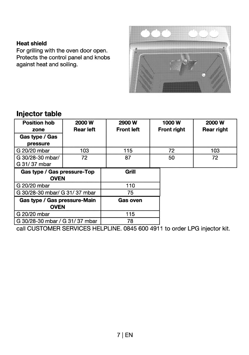
Injector
table;
аиан
7
2
Safety
instructions
..................
8
Basic
safety
instructions.......................
8
Safety
when
working
with
electricity
. 9
Safety
when
working
with
gas
..........
9
Intended
use
...................................
10
Safety
for
children
...........................
10
DIS
DOSE
mE
a
10
Disposing
of
packaging
material.....
10
Old
equipment.................................
11
Future
transportation.......................
11
3
Installation
............................
12
Before
installation
...............................
12
Installation
and
connection.................
13
Gas
сопуегѕіопћ...................................
16
4
Preparation
..........................-
21
Tips
for
saving
energy
........................
21
First
cleaning
of
the
appliance
........
21
Initial
heating
...................................
21
E
How
to
use
the
hob..............
22
General
information
on
cooking..........
22
How
to
use
hobs.................................
22
6
How
to
operate
Ше
омеп.....
24
General
information
on
baking,
roasting
апа
ОПШПО
сое
ае
оаа
24
How
їо
use
the
gas
oven
....................
25
Cooking
times
table.........................
25
How
to
operate
the
gas
grill-
Top
oven27
Cooking
times
table.........................
28
Maintenance
and
care
........
29
General
information
............................
29
How
to
clean
the
hob..........................
29
Cleaning
the
control
panel..................
29
Cleaning
the
oven
...............................
29
Removal
of
top
oven
door
.................
29
Removing
the
door
inner
glass
...........
30
Replacing
the
oven
lamp
....................
31
8
Troubleshooting
...................
32
9
Guarantee
and
Service
........
34
3
|
EN