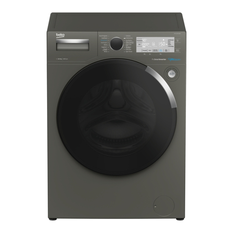
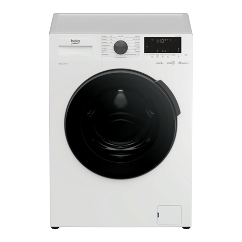
Beko Arcelik BLG15 C7S User manual

BLG15 C7S SERVICE MANUAL
Sensitivity: Public
BLG15 C7S CONTROL SYSTEM
WASHING MACHINE
SERVICE MANUAL
SERVICE MANUAL NO:00

BLG15 C7S SERVICE MANUAL
Sensitivity: Public
1 COVER
2 CONTENTS
1COVER..................................................................................................................................................... 2
2CONTENTS...............................................................................................................................................2
3COMPONENT OPERATING PRINCIPLES .................................................................................................... 4
3.1.1 Electronic Board Assembly .............................................................................................................. 4
3.2 Water Inlet Valve ................................................................................................................................. 5
3.3 Water Level Sensor............................................................................................................................... 5
3.4 Washing Motor .................................................................................................................................... 6
3.4.1 Atlas Motor ..................................................................................................................................... 6
3.5 Heater .................................................................................................................................................. 7
3.6 NTC....................................................................................................................................................... 7
3.7 Drain Pump .......................................................................................................................................... 8
3.8 Safety Switch (Door lock/Solenoid) ...................................................................................................... 9
3.9 HomeWhiz Feature and Remote Control Function............................................................................. 12
3.9.1 HomeWhiz Setup ........................................................................................................................... 12
3.9.2 Setting up a washing machine that is connected to someone else's account ............................... 14
3.9.3 Remote Control function and its use ............................................................................................. 14
3.9.4 Troubleshooting ............................................................................................................................ 15
3.10 Steamcure ..................................................................................................................................... 15
4SERVICE FUNCTION TEST....................................................................................................................... 17
STEP 1: SWITCHING TO THE SERVICE PROGRAMME....................................................................................................... 17
STEP 2: BLUETOOTH TEST ....................................................................................................................................... 18
STEP 3: SOFTWARE VERSION CHECK.......................................................................................................................... 18
STEP 4: LED AND LCD SEGMENT CHECK .................................................................................................................... 18
STEP 5: MOTOR COUNTER CLOCKWISE WASH CHECK .................................................................................................... 19
STEP 6: MOTOR CLOCKWISE WASH CHECK.................................................................................................................. 19
PRESS THE "START/PAUSE"BUTTON......................................................................................................................... 19
NOTE: IF YOU TURN THE KNOB TO OFF POSITION,THE MACHINE WILL SWITCH TO "OFF" MODE. ......................................... 19
STEP 7: NTC CHECK,MAINS VOLTAGE ADC INPUT CHECK,............................................................................................ 19
MACHINE SPIN SPEED (MAX.SPEED)CHECK ................................................................................................................ 19
STEP 8: DRYING MODULE CHECK STEP 1 .................................................................................................................... 20
STEP 9: DRYING MODULE CHECK STEP 2 .................................................................................................................... 21
STEP 10: PREWASH VALVE,AND PREWASH VALVE FLOW METER CHECK ......................................................................... 21
STEP 11: MAIN WASH VALVE,AND MAIN WASH VALVE FLOW METER CHECK ................................................................. 22
DESCRIPTION:....................................................................................................................................................... 22
STEP 12: SOFTENER COMPARTMENT CHECK,DETERGENT BOX SIPHON CHECK.................................................................... 23
STEP 13: CONDENSER VALVE CHECK.......................................................................................................................... 23
STEP 14: HOT WATER VALVE CHECK.......................................................................................................................... 24
STEP 15: HEATER CHECK,WATER LEVEL SENSOR CHECK ................................................................................................ 24
JET SYSTEM CHECK,MOTOR CLOCKWISE WASH CHECK................................................................................................... 24
STEP 16: BLUETOOTH CONNECTION CHECK ................................................................................................................ 25
DESCRIPTION:....................................................................................................................................................... 25
STEP 17: PUMP CHECK........................................................................................................................................... 26
DESCRIPTION:....................................................................................................................................................... 26
STEP 18: DISPLAY OF THE ERRORS OCCURRED IN THE SERVICE MODE .............................................................................. 26
DESCRIPTION:....................................................................................................................................................... 26
STEP 19: HOW MANY TIMES HAS THE SERVICE MODE BEEN COMPLETED SUCCESSFULLY?.................................................. 27
DESCRIPTION:....................................................................................................................................................... 27
5EQUIPMENT/APPARATUS TO BE USED IN COMPONENT INSTALLATION- REMOVAL.............................. 28
SHOCK ABSORBER PIN REMOVAL APPARATUS............................................................................................................. 28

BLG15 C7S SERVICE MANUAL
Sensitivity: Public
6COMPONENT INSTALLATION/REMOVAL............................................................................................... 31
6.1 Upper Table Installation/Removal ..................................................................................................... 31
6.1.1 Installation .................................................................................................................................... 31
6.1.2 Removal......................................................................................................................................... 33
6.2 Panel Installation / Removal .............................................................................................................. 34
6.2.1 Installation .................................................................................................................................... 34
6.2.2 Installation .................................................................................................................................... 36
6.3 Detergent Box Installation / Removal / Installation........................................................................... 37
6.4 Display Board Assembly Installation/Removal................................................................................... 40
6.5 Power board installation/removal ..................................................................................................... 41
6.6 Door Group Attachment/ Detachment .............................................................................................. 45
6.6.1.Attachment......................................................................................................................................... 45
Exterior Decorative Handle Cover................................................................................................................ 45
Exterior Door................................................................................................................................................ 46
Handle.......................................................................................................................................................... 47
Decorative Door........................................................................................................................................... 47
Lock Hook .................................................................................................................................................... 49
Glass ............................................................................................................................................................ 50
Exterior Door Assembly................................................................................................................................ 50
6.7 Pump cover installation/removal....................................................................................................... 51
6.8 Front Wall Installation/Removal ........................................................................................................ 52
6.8.1 Removal......................................................................................................................................... 52
6.9 Installation ......................................................................................................................................... 55
6.10 Detergent Box Installation/Removal ............................................................................................. 57
6.10.1 Removal.................................................................................................................................... 57
6.10.2 Removal.................................................................................................................................... 58
6.11 Dual Valve Installation/Removal................................................................................................... 59
6.12 Water Level Sensor Installation / Removal.................................................................................... 60
6.13 Power Cable Installation/Removal ................................................................................................ 61
6.14 Interference Suppression Filter Installation/Removal ................................................................... 62
6.15 Washing Motor ............................................................................................................................. 62
6.15.1 ATLAS motor ............................................................................................................................. 62
6.16 Atlas Vektör card disassembly / assembly .................................................................................... 63
6.17 Poly V Belt Installation .................................................................................................................. 64
6.18 Shock Absorber and Shock Absorber Pin Installation/Removal..................................................... 65
6.18.1 Shock Absorber Installation/Removal....................................................................................... 66
6.19 Upper Counterweight Installation/Removal ................................................................................. 66
6.20 Lower Counterweight Installation/Removal.................................................................................. 67
6.21 Drain Pump Installation/Removal ................................................................................................. 67
6.22 Water Inlet Hose Installation/Removal ......................................................................................... 68
6.23 Drain Hose Installation/Removal .................................................................................................. 69
8LIST OF COMPONENTS .......................................................................................................................... 70
9FIGURE AND PICTURE LIST..................................................................................................................... 70
10 TABLE LIST............................................................................................................................................. 72

BLG15 C7S SERVICE MANUAL
Sensitivity: Public
3 COMPONENT OPERATING PRINCIPLES
3.1.1 Electronic Board Assembly
Picture 3.1 Power board
Picture 3.2 Display board
Picture 3.3 Vector board
Electronic board assembly comprises
the following:
•Power board
•Display board
•Vector motor board and
the extension cable.
The power board is designed to drive all
components and find high-voltage
circuits. Power is distributed to all high-
voltage components on the product, and
the mains input comes here.
The display board allows the user to
select programmes and other auxiliary
functions, as well as carrying out main
board functions.
Wash programs which are written onto
the microprocessor on the display board,
washing and spinning motor profiles,
protection algorithms and components
(motor, heater, pump, valves, door safety
lock, ntc, water level sensor,
spinning/temperature selection, water
meter) are controlled. Along with the LED
display, there are also buttons used for
function selection.

BLG15 C7S SERVICE MANUAL
Sensitivity: Public
3.2 Water Inlet Valve
It is used to get adequate water for the machine when necessary.
Picture 3.4 Water inlet valve
Dual valve is used in the models with one water inlet and without steam
generator,
Triple valve is used in the models with one water inlet and steam generator (the
steam valve feature is explained in the relevant section),
Dual valve and an additional single valve are used in the models with double
water inlet and without steam generator,
Triple valve and an additional single valve is used in the models with dual water
inlet and steam generator (the steam valve feature is explained in the relevant
section),
Valves are activated via the triacs on the electronic board.
They are activated via the both valves in the softener step by use of crashed water
directing system and the water is directed to the medium compartment of the
detergent box.
3.3 Water Level Sensor
An analog water level sensor which is fed by 5 V voltage is used. This sensor ensures
that the water level is determined instantly with the frequency values which it generates
against the pressure created. There are frequency values corresponding to the all
pressure values. An infinite number of levels can be determined in the analog water
level sensor. Water levels change according to the wash criteria of the designed
program depending on the selected program, temperature and auxiliary function.
Analog water level sensors are pressure –displacement inverter components in
general.
Analog water level sensors generates frequency modulation as output.
There are basically 2 capacitors, 1 coil and an inverter circuit on itself or the control
system to which it is connected.
Pressure increase pushes a ferrite part inside the sensor into the coil. Therefore L
(inductance) value of coilwinding changes and the output value of the sensor –inverter
system changes. Therefore pressure value can be measured in an analog manner.
Operating Voltage : 220 / 240VAC 50-60 Hz
Nominal Power : 5 –8 W
Flowrate : 10 l/min
Operating Voltage : T85ºC
Coil Resistance : 3400 –4850
Table of contents
Other Beko Washer manuals

Beko
Beko WMY 61283 CS PTLB2 User manual

Beko
Beko D2 8101 ES User manual

Beko
Beko WMB 61621 User manual

Beko
Beko WMB 61031 M User manual

Beko
Beko WMY 814831 User manual

Beko
Beko B5WT5941082W User manual

Beko
Beko WTV 8612 XMCI User manual

Beko
Beko WTG941B2JW User manual

Beko
Beko WY104344W User manual

Beko
Beko D2 7101E User manual

Beko
Beko WRA 9612 XSWR User manual

Beko
Beko B3WFU58415W User manual

Beko
Beko WUX81282WI/IT User manual

Beko
Beko WR84PB44DG User manual

Beko
Beko 60081474CHD1 User manual

Beko
Beko WTV 7513 XST User manual

Beko
Beko B3WF U7841 WB User manual

Beko
Beko WSTE6511BWW User manual

Beko
Beko WTK104121A User manual

Beko
Beko WMB 61222 MC User manual