MV-830 Quick Setup Guide
© 2018 Grass Valley, a Belden brand
MV-830 Quick Setup Guide
www.grassvalley.com
1) Fitting an MV-830 into a Sirius 830 Router
Router Power Supplies: Sirius 830 routers have powerful power supplies. In most cases, these are sufficient for powering
MV-830(s). Grass Valley recommends checking your router power supply configuration with Grass Valley support before
fitting MV-830(s) into the router. (For contact details, see https://www.grassvalley.com/support/sam/)
MV-830: This is a double-width Sirius 830 module, comprising double-width Rear & Front modules. See Figure 1.
Fitting instructions:
1. If SFP modules are supplied separately, fit them to the MV-830-RP.
An MV-830 module occupies a pair of (front and rear) router input/output slots. For example: slot-pairs 1 & 2; or 11 & 12.
Note: From the front of the router, slots are numbered from left to right. From the rear, numbering is right to left.
2. Ensure a vertical ‘slot-pair’ of router module slots are available and empty.
MV-830 modules may be hot-plugged.
Go to the rearof the router:
3. Remove any blanking plate already covering the router rear slots.
4. Fit the MV-830-RP rear module. Secure with four screws.
Go to the front of the router:
5. Open the router front outer door and the lower router fan door.
6. Insert the MV-830-MB front module. Push the module into the slots
with the module ejector handles.
Ensure the module is pushed fully into the slots with module ejector handles pushed fully inwards.
7. Close the router’s fan door and front outer door.
Caution: Always keep router fan doors closed to ensure correct unit ventilation
and operation. Only open a router fan door for a maximum of 2 minutes.
Booting: After the front module is fitted, the MV-830 begins to boot up.
Booting up lasts for approximately 1 to 2 minutes. During boot-up:
8. A splash screen appears on each active multiviewer head display output.
Connect a monitor to each. See Figure 3. IP addresses are shown.
9. After booting, each multiviewer head display output shows a default video
wall. See Figure 5 on page 3.
Figure 1 MV-830 Multiviewer Double-width Front and Rear Modules
Input/output slot numbering and slot-pairs for MV-830, (slot-pairs):
• From frontof router: (1 2) (3 4) (5 6) (7 8) (9 10) (11 12) (13 14) (15 16) (17 18) (19 20) (21 22) (23 24)
• From rear of router: (24 23) (22 21) (20 19) (18 17) (16 15) (14 13) (12 11) (10 9) (8 7) (6 5) (4 3) (2 1)
Figure 2 Sirius 830 Router
Sirius 830 router frame
Fit an MV-830
into a pair of input/output
module slots of a
Sirius 830 router frame.
Important:
MV-830 is
not compatible with
Sirius 840/850 routers.
MV-830-MB MV-830-RP
Rear handles
Front
ejector
handles
Securing
screws
Figure 3 MV-830 Splash Screen
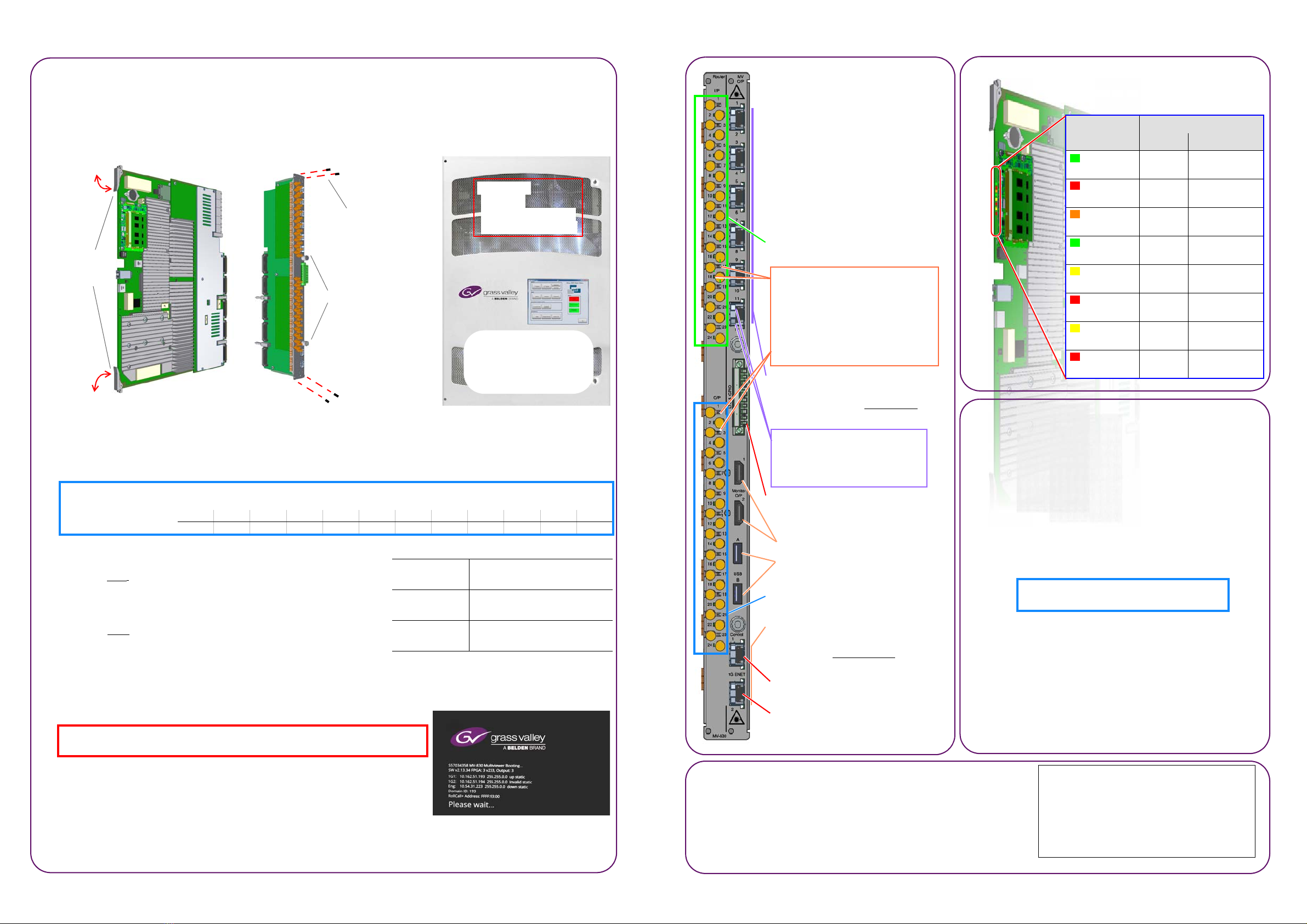
2) Rear Connections
Connect the following:
1. Router Video Inputs to the video
signal sources.
2. Router Video Outputs to the
equipment that they should feed.
3. Head Display Outputs 1 to 4 to
the monitor displays.
4. Network cable to Ethernet port 1,
Control 1.
Router Video Inputs 1 to 24 (HD-BNC)
Video Status LEDs:
Red: No valid signal.
Yellow: SD SDI signal.
Yellow flashing: DVB-ASI signal.
Green: 1080i/p HD signal.
Green flashing: 720p HD signal.
Blue: 3G SDI signal.
Head Display Outputs 1 to 12:
(To monitor displays.)
6-off SFP cages for Video SFPs.
(‘2xHD-BNC’ or ‘2xFiber’ per SFP)
Display Output Status LEDs:
Blue: Licensed and SFP fitted.
Red: Licensed, no SFP fitted.
Off: Unlicensed output.
LTC & G P I O: (pin 1)
Screw terminal connector.
Monitor O/P 1 & 2(not used).
USBA& B(not used).
Router Video Outputs 1 to 24
(HD-BNC)
Ethernet:
(Control network.)
SFP cages for Ethernet SFPs.
1G Ethernet Ports.
Port 1: ‘Control 1’, 1G ENET (“1G1”)
Default IP address: 10.54.31.221
Port 2 (“1G2”)
Page 2
Page 1
3) MV-830-MB Front Module Indicators
.
LED Status
OK Fault
ACT Flash -
ERR Off On,
error
WRN Off On,
warning
OK On Flash,
comms fault
LOCAL
CMD OK
Flash, On
or Off -
LOCAL
CMD ERR Off Flash,
message error
REMOTE
CMD OK
Flash, On
or Off -
REMOTE
CMD ERR Off Flash,
message error
LEDs along the MV-830-MB module’s front edge are:
4) Network Configuration
1. Start Grass Valley RollCall Control Panel (v4.17.1 or later)
on a laptop PC. Click the Build Network icon.
2. Enter the MV-830 Ethernet port 1 default IP address,
10.54.31.221.
RollCall connects to the MV-830.
3. Navigate to the RollCall System-Setup screen.
4. Set up Network Settings relevant to your house network
(IP address, Subnet mask, etc).
5. In RollCall Settings, set up Unit number (default = 01)
and Domain ID (default = 100) for the MV-830.
Note: Unit number must be unique for each unit.
Typically,‘Domain ID’ is the same for each unit.
Restart:
6. In RollCall System-Setup screen:
Click System Reset; then click Confirm.
The MV-830 boots up and a splash screen shows the unit’s
IP address and other details (see Figure 3).
After MV-830 has restarted, initial network configuration is
complete.
7. Disconnect MV-830 Ethernet port 1 from laptop PC.
And connect the port to the house network.
Operating
Environment
5ºC to 30 ºC ambient.
10 to 90% (non-condensing)
MV-830
Weight
MV-830-MB: 3.5 kg (~7.7lb).
MV-830-RP: 1 kg (~2.2lb).
Power
Consumption 250 W
Table 1 MV-830 Specification
Figure 4 Rear Panel
Module Type - Input slot MV830Input
Module Type - Output slot MV830Output
Input and Output Ports MV830
Logical Sources VideoSource
Logical Destinations VideoDest
Router Frame Number 14
EmbeddedTimecodeEnable True
Table 2 Configuration Items
5) Router Configuration
Both of the router slots used by the MV-830 must be set up in the
router configuration. See items shown in Table 2.
Default Multiviewer Monitoring Mode:
All MV-830‘s router video outputs and inputs (48 total) are monitored
by the multiviewer when slot configuration items Redundant
Crosspoint Enable and Main Output Follow are all enabled (default).


