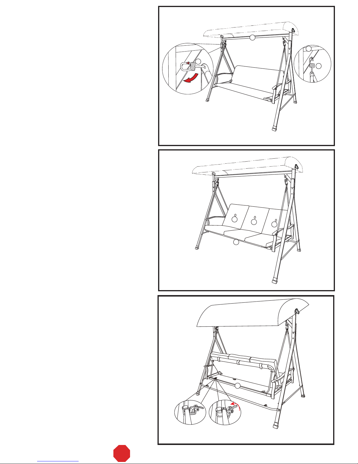
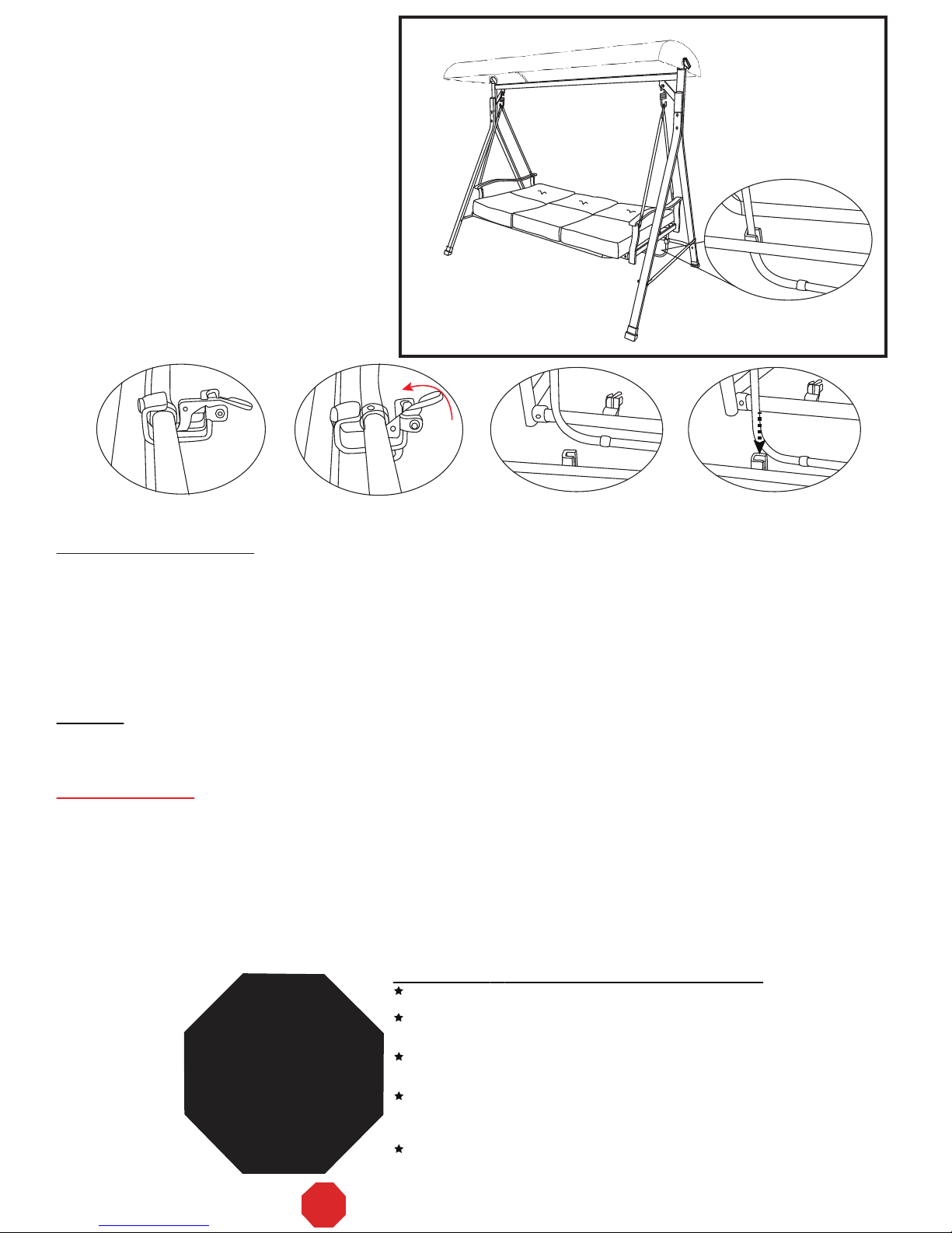
Belden RUS498X User manual

ASSEMBLY INSTRUCTIONS
ATTENTION: THIS PRODUCT IS NOT FOR COMMERCIAL USE
INTENDED FOR RESIDENTIAL USE ONLY.
RUS498X
PAGE 1 OF 7
V-3 COURTYARD CREATIONS INC.
Use the correct bolts as indicated. Do not tighten any of the bolts until the swing is completely
assembled.
Do not discard of any of the packaging until you have checked that you have all of the parts and
fittings required.
Keep children away during assembly. This item contains small parts that can be swallowed by
children. Children should always be under direct adult supervision while using this product.
Retain these assembly instructions for future reference.
Quote the following FQC NO. when contacting the service center.
!
!
!
!
!
SERVICE CENTER TOLL FREE NO.
TEL: 1-877-539-7436
FAX: 1-877-539-7439
STOP DO NOT RETURN TO THE STORE!

TOP CROSS BEAM
W/ADJUSTABLE TEETH
REAR UPRIGHT SUPPORT
FRONT UPRIGHT SUPPORT
LATERAL CROSS BRACE
REAR CROSS BRACE
RIGHT SEAT ARM
LEFT SEAT ARM
SEAT FRONT SUPPORT
SEAT REAR SUPPORT
SEAT ASSEMBLY
SWING ARM TUBE
PLASTIC JOINT COVER
SUSPENSION SPRING
RUS498X-CS09-8
62RUS498WN101
62RUS498WN102
62RUS498WI101
RUS498X-CS09-9
62RUS422WH102
62RUS498X301
RUS498X-CS01-3
RUS498X-CS01-2
62RUS416BH101
RUS498X-CS09-7
RUS498X-CS11-1
62RUS487WM101
17GA20405201-Y3
17C40A0714001YX
Q'TY
BOLT M8*80
BOLT M6*60
WASHER d6.5*D16*1.2
PLASTIC WASHER
CANOPY/FRAME
CONNECTOR
PLASTIC SCREW
NUT WRENCH 13 &17MM
HEX. KEY WRENCH 6MM
CUSHION
CANOPY
17C01A0826011YX
17C40A0721001YX
17FA05050401-YX
18060616151401
1809030201
18020605001
18000018001
17KAB1201----Y4
17KAA0201----Y4
61R498XC00000BA
61R498XD00001BA
1
2
3
4
5
6
7
8
9
10
11
12
13
14
15
16
17
18
19
20
21
22
23
24
25
26
27
28
29
30
31
32
34
35
1
2
2
2
1
2
2
1
1
1
1
1
4
2
6
2
4
28
4
2
4
2
2
1
1
3
1
PAGE 2 OF 7
A. Read instructions thoroughly. Acquaint yourself with the inventory of parts and the
accompanying drawings to ensure safe and proper assembly.
B. You will need the following tools
- Phillips Screwdriver
- Nut Wrench (See Part #31)
- Hex. Key Wrench (See Part #32 and #33)
C. Lay out all of the parts on a flat surface and identify them using the table below.
PARTS LIST
BOLT M6*40
WASHER d8.5*D17*1.6
17FA08060601-YX 12
HEX. KEY WRENCH 4MM
17KAA0101----Y4
33
1
PLASTIC NUT M8*P1.25
18000C06001
PLASTIC NUT M6*P1.0 1418000C23001
JAM NUT M8*1.25
17D03A040401-YX 2
PART
NO. MATERIAL CODE PART
SIDE CANOPY BRACE
FRONT/REAR CANOPY BRACE
4
BOLT M8*65
17C01A0822061YX
BOLT M6*65
17C40A0722001YX 4
428000221023 LEG CAP
SCREW ST4.2*16
17C17A1306001YX 4
V-3
STOP DO NOT RETURN TO THE STORE!

PAGE 3 OF 7
Step 3:
Fasten the lateral cross braces (#4) to upright
supports (#2 and #3) by using bolts (#16),
washers (#22), and plastic nuts (#26). Repeat
the same procedure for both sides.
See Fig. A – Step 3.
Step 5:
Insert the leg caps (#14) into all of the base feet.
See Fig. A – Step 5.
Step 1
Step 2
Step 3
Step 4
Step 5
Fig. A
Step 1:
Fasten the front and the rear upright supports
(#2 and #3) together at the top by using bolts
(#15), washers (#21), and plastic nuts (#25).
Repeat the same procedure for both sides.
Keep the bolts loose. See Fig. A – Step 1. Do not tighten the bolts
after step 1. Fasten all
of the bolts after Fig A.
Step 2:
At both ends, insert the assembled upright
supports (#2 and #3) into the top cross beam
w/adjustable teeth (#1). Tighten all of the plastic
nuts and bolts now. See Fig. A – Step 2.
Step 4:
Fasten the rear cross brace (#5) to the rear
upright supports (#3) by using bolts (#17),
washers (#22), and plastic nuts (#26). Tighten
all of the nuts and bolts. See Fig. A – Step 4.
15 21
21
21
21
15
16
22
22 26
17
14
14
14
14
22
22
26
2
2
2
3
23
3
3
3
3
3
2
23
2
4
5
4
3
1
ASSEMBLY (Note: When fastening with nuts
and bolts, always use a washer (#21 or #22)
between the tube and the bolt or the tube and
the nut.)
25
25
Note:
The labelled arrow marks on the rear cross
brace (#5) should be facing upwards.
V-3
STOP DO NOT RETURN TO THE STORE!

PAGE 4 OF 7
Fig. C
34
27
28 27 28
1
Step 10:
Fasten the canopy/frame connectors (#27) to
the adjustable teeth on the top cross beam w/
adjustable teeth (#1) by using a plastic screw
(#28). Repeat this procedure for both sides.
Fig. B
Step 1
Step 3
Step 5
Step 2
Step 6 :
Slide the canopy/frame connectors (#27) on to
the side canopy braces (#6). In the pre-drilled
holes, fasten them together by using screws
(#20). Make sure that the teeth on the
canopy/frame connectors are facing toward the
inside of the frame.
See Fig. B – Step 1 and Step 2.
Step 7:
Insert the front/rear canopy braces (#7) into
the sleeves of the canopy (#34) on both sides.
See Fig. B – Step 3.
Step 8:
Insert the tube ends of the front and rear canopy
braces (#7) into the side canopy braces (#6).
See Fig. B – Step 4.
Step 9:
Velcro the canopy (#34) to the side canopy
braces (#6). See Fig. B – Step 5.
27 27
20
20
6
6
6
6
7
34
Step 4
6
6
7
7
34
34
7
V-3
STOP DO NOT RETURN TO THE STORE!

PAGE 5 OF 7
Step 11:
Insert seat arms (#8 and #9) into seat
supports (#10 and #11) and fasten them together
by using plastic joint covers (#29), bolts (#17),
washers (#22), and plastic nuts (#26).
See Fig. D – Step 1.
Note:
1. The label marked "back" on the right seat arm
(#8) should coincide with the label marked
"back" on the seat rear support (#11) to ensure
proper assembly.
2. The clip holder side of the seat rear support
(#11) must face toward the inside of the swing
and the opening side of the clip holder must
be facing upward.
Step 12:
Open the seat assembly (#12) and attach its
back to seat arms (#8 and #9) by using bolts
(#18), washers (#21), plastic washers (#30), and
jam nuts (#24). Repeat the same procedure for
both sides. See Fig. D – Step 2.
Step 13:
Make sure that the support brace on the seat
assembly (#12) is fully inserted into the clip
holders on the seat rear support (#11).
See Fig. D – Step 3.
Step 14:
Attach the swing arm tubes (#13) to seat arms
(#8 and #9) by using bolts (#19), washers (#22),
and plastic nuts (#26). Repeat the same
procedure for both sides. See Fig. D – Step 4.
Step 15:
Hook the suspension springs (#23) into the top
of both holes in the swing arm tubes (#13).
Repeat the same procedure for both sides.
See Fig. D – Step 5.
back
back
back
back
Fig. D
back
back
8
8
10
18 21 21 24
30
12
12
11
13
13 13 13 13
13 13 26
26
22 22
22 22
19
19
13
23
23
23
23
11
29
17 22
2226
9
9
support brace
Step 1
Step 2
Step 3
Step 4
Step 5
back
back
8
9
V-3
STOP DO NOT RETURN TO THE STORE!

Fig. E
Step 16:
Hang the opposite ends of the suspension
springs (#23) into the holes located in the
angled braces on the top cross beam w/adjustable
teeth (#1). See Fig. E.
Warning:
Make sure that both ends of the suspension
springs (#23) go completely through the holes
in the angled braces on the top cross beam
w/adjustable teeth (#1) and the swing arm
tubes (#13).
23 23
1
1
Step 17:
To assure stability, double check that all of the
bolts have been completely tightened.
Step 19:
Make sure that the safety locks on the seat
rear support (#11) are fully locked whenever
the seat assembly is in a swinging position.
See Fig. G – 1 (SEAT). To have the swing in
a bed position, open both of the safety locks.
See Fig. G – 2 (BED).
Step 18:
Place the cushions (#35) onto the seat
assembly (#12). See Fig. F.
Fig. F
Fig. G
G–1(SEAT) G–2(BED)
PAGE 6 OF 7
35 35
12
35
11
V-3
STOP DO NOT RETURN TO THE STORE!

Step 20:
To flatten the seat assembly, lift up the safety
locks and remove the support brace.
See Fig. H1 and Fig. H2.
Then, insert the support brace into the rear
cross brace (#5). The seat assembly should
now be in a secured position and not moving
at all. See Fig. H3, Fig. H4, and Fig. H5.
Fig. H Fig. H5
Warning:
To avoid danger of suffocation, always keep
plastic bags or small parts away from babies
and children.
Special Warnings
1. The user of this swing should always inspect it before each use.
2. It is essential to place this swing on level ground and not less than 6 feet away from any obstruction; such as
fences, garages, houses, overhanging branches, laundry lines, or electrical wires.
3. Check the tightness of all of the nuts and bolts on a regular basis.
4. Make sure that the suspension springs are properly secured before each use.
5. Always remove the canopy in heavy wind conditions. Otherwise, the swing may tip over and cause damage to
its parts.
6. The manufacturer will not accept responsibility for unauthorized repairs or modifications to the swing or its parts.
7. Oil all of the metal parts that move regularly.
8. The weight limit is 750 lbs.
PAGE 7 OF 7
Fig. H1 Fig. H2 Fig. H3 Fig. H4
Cleaning and Maintenance
• Wash frame and fabric parts with mild soap and water, rinse thoroughly, and dry completely. Do not use bleach,
acid, or other solvents on the frame or fabric parts.
• The cushions and canopy may be washed on the surface only by using mild soap and water or commercial
foaming upholstery cleaner if necessary. If washed, rinse well and hang to dry. Do not machine wash or dry.
• We recommend the use of furniture covers when not in use.
• Inspect and tighten all bolts and fasteners on a regular basis to ensure the proper performance and safety of
your swing.
• In order to prolong the life and beauty of your swing, we recommend that it be stored in a dry and protected area
during off season periods.
The store where you made your purchase
does not stock parts for this item.
If you need parts,
whether they are missing or damaged,
STOP!
Missing A Part?
No Need To Go Back To
The Store
Call us between 9:00 AM and 4:30 PM
Eastern Time Monday through Friday
For further assistance,
please visit us at
Call Toll Free:
TEL: 1-877-539-7436
FAX: 1-877-539-7439
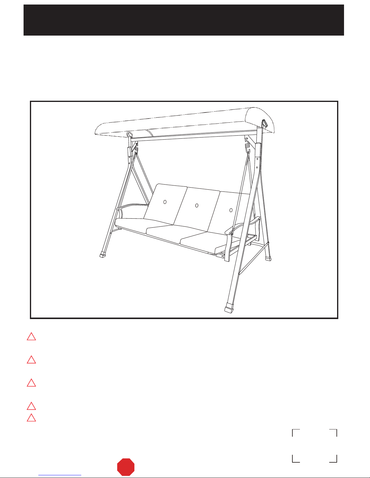
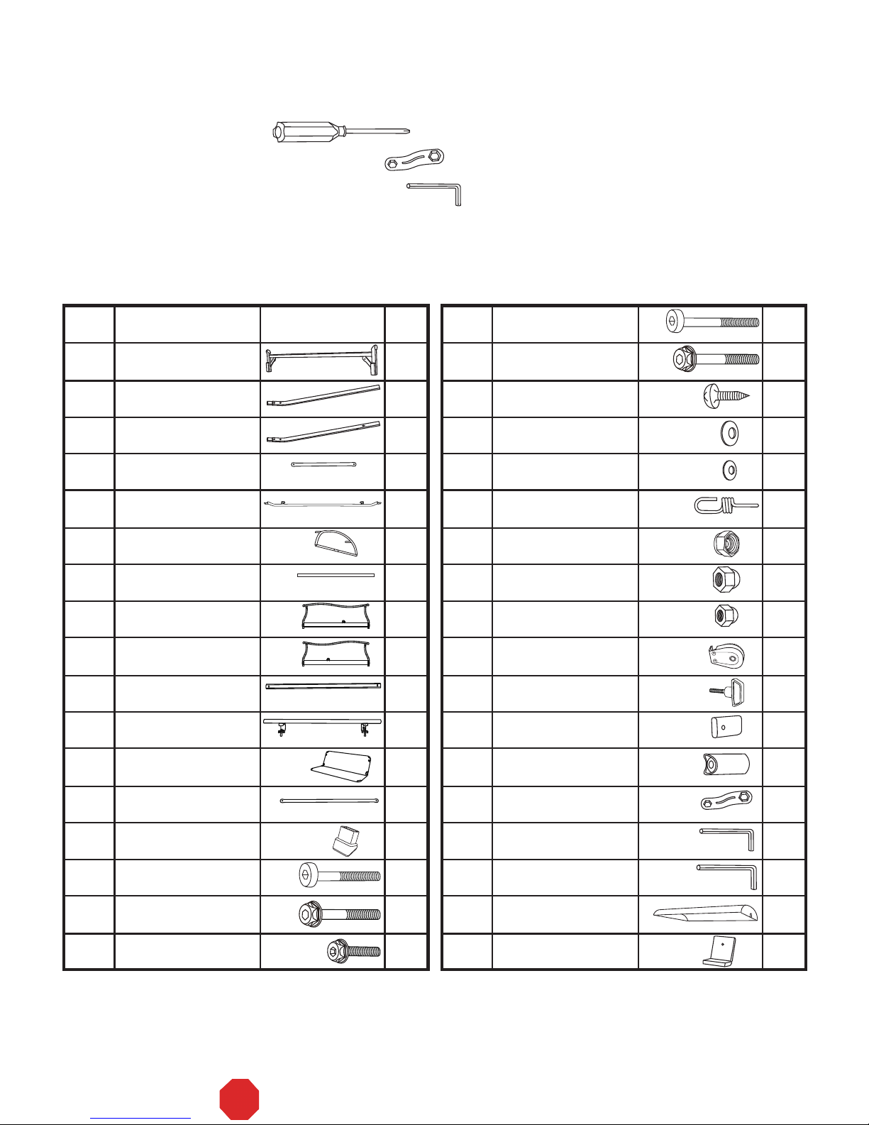
READ THESE INSTRUCTIONS COMPLETELY BEFORE STARTING ASSEMBLY
SEPARATE AND IDENTIFY ALL OF THE PARTS,MAKING SURE THAT
YOUHAVE ALL OF THEPARTSLISTED.
IF YOU DO NOTLOCATE ALL OF THE PARTS LISTED, INSPECT THE
PACKING MATERIAL FOR SMALL PARTSTHAT MAYHAVEBECOME
SEPARATED DURING SHIPMENT.
IF YOU EXPERIENCEANY DIFFICULTY DURING ASSEMBLYOR IF ANY
PARTS ARE MISSING OR DAMAGED,CALL THE HELP LINE AT
1-877-539-7436 BEFORERETURNING THIS ITEM TO THE STORE.
PROVIDE THEFOLLOWING INFORMATION WHEN CALLING:
1-MODEL NUMBER OF THEPRODUCT.
2-PARTNUMBER AND MATERIAL CODE OF THE PARTFROM THE PARTS
LIST.
MOST PROBLEMS CAN BERESOLVED WITHOUT RETURNING THIS
PRODUCT TO THERETAILER.
Warranty
• This product is covered by Courtyard Creations Inc.'s. one–year limited warranty.
• Proof of purchase (dated register receipt) is required for warranty claims.
• It remains the customer’s responsibility for freight and packing charges to and from the service center.
V-3
STOP DO NOT RETURN TO THE STORE!

RUS498X
PÁGINA 1 DE 7
V-3
ALTO ¡NO DEVUELVA ESTE PRODUCTO A LA TIENDA!
COURTYARD CREATIONS INC.
Utilice los tornillos correctos, según se indica. No apriete ninguno de los tornillos hasta que el
columpio esté completamente ensamblado.
No tire el empaque hasta que haya comprobado que tiene todas las partes y los accesorios
necesarios.
No deje que los niños se acerquen durante el ensamblado. Este producto contiene piezas pequeñas que los niños
pueden ingerir. Mientras usen este producto, los niños siempre deberán estar bajo la supervisión directa de un adulto.
Conserve estas instrucciones para referencia futura.
Cuando se comunique con el centro de servicio, proporcione siempre el siguiente código de
control de calidad (FQC, por sus siglas en inglés).
!
!
!
!
!
NÚMERO GRATUITO DEL CENTRO DE SERVICIO
TEL: 1-877-539-7436
FAX: 1-877-539-7439
INSTRUCCIONES DE ARMADO
ATENCIÓN: ESTE PRODUCTO NO ES PARA USO COMERCIAL;
ESTÁ DISEÑADO ÚNICAMENTE PARA USO RESIDENCIAL.

BARRA TRANSVERSAL SUPERIOR
CON DIENTES AJUSTABLES
SOPORTE VERTICAL TRASERO
SOPORTE VERTICAL DELANTERO
REFUERZO
TRANSVERSAL LATERAL
REFUERZO
TRANSVERSAL TRASERO
BRAZO DERECHO
BRAZO IZQUIERDO
SOPORTE
DELANTERO DEL ASIENTO
SOPORTE TRASERO DEL ASIENTO
ASIENTO
TUBO DEL DESCANSABRAZOS
CUBIERTA
DE PLÁSTICO PARA JUNTAS
RESORTE DE SUSPENSIÓN
RUS498X-CS09-8
62RUS498WN101
62RUS498WN102
62RUS498WI101
RUS498X-CS09-9
62RUS422WH102
62RUS498X301
RUS498X-CS01-3
RUS498X-CS01-2
62RUS416BH101
RUS498X-CS09-7
RUS498X-CS11-1
62RUS487WM101
17GA20405201-Y3
17C40A0714001YX
CANT.
TORNILLO M8*80
TORNILLO M6*60
RONDANA d6.5*D16*1.2
ARANDELA DE PLÁSTICO
CONECTOR
TOLDO-ARMAZÓN
TORNILLO DE PLÁSTICO
LLAVE DE TUERCAS DE 13 Y 17MM
LLAVE ALLEN DE 6MM
COJÍN
TOLDO
17C01A0826011YX
17C40A0721001YX
17FA05050401-YX
18060616151401
1809030201
18020605001
18000018001
17KAB1201----Y4
17KAA0201----Y4
61R498XC00000BA
61R498XD00001BA
1
2
3
4
5
6
7
8
9
10
11
12
13
14
15
16
17
18
19
20
21
22
23
24
25
26
27
28
29
30
31
32
34
35
1
2
2
2
1
2
2
1
1
1
1
1
4
2
6
2
4
28
4
2
4
2
2
1
1
3
1
A. Lea las instrucciones cuidadosamente. Familiarícese con el inventario de partes y las ilustraciones
correspondientes para que pueda armar el columpio segura y adecuadamente.
B. Se necesitan las siguientes herramientas:
- Desarmador de cruz
- Llave de tuercas (vea la parte #31)
- Llave Allen (vea las partes #32 y #33)
C. Extienda todas las partes en una superficie plana e identifíquelas con ayuda de la
siguiente tabla:
LISTA DE PARTES
TORNILLO M6*40
RONDANA d8.5*D17*1.6
17FA08060601-YX 12
LLAVE ALLEN DE 4MM
17KAA0101----Y4
33
1
TUERCA DE PLÁSTICO M8*P1.25
18000C06001
TUERCA DE PLÁSTICO M6*P1.0 1418000C23001
TUERCA DE SEGURIDAD M8*1.25
17D03A040401-YX 2
No. DE
PARTE
CÓDIGO DE
MATERIAL PARTE
ARMAZÓN LATERAL DEL TOLDO
TRAVESAÑO DELANTERO/
TRASERO DEL TOLDO
4
TORNILLO M8*65
17C01A0822061YX
TORNILLO M6*65
17C40A0722001YX 4
428000221023 TAPA DE LA PATA
TORNILLO ST4.2*16
17C17A1306001YX 4
V-3 PÁGINA 2 DE 7
ALTO ¡NO DEVUELVA ESTE PRODUCTO A LA TIENDA!

Paso 3:
Sujete los refuerzos transversales laterales (#4)
a los soportes verticales (#2 y #3) con ayuda de
los tornillos (#16), las rondanas (#22) y las
tuercas de plástico (#26). Repita el mismo
procedimiento para ambos lados.
Consulte la figura A, paso 3.
Paso 5:
Coloque los tapones de las patas (#14) en
todas las patas del columpio. Consulte la
figura A, paso 5.
Paso 1
Paso 2
Paso 3
Paso 4
Paso 5
Paso 1:
Sujete los soportes verticales delantero y
trasero (#2 y #3) en la parte superior con
ayuda de los tornillos (#15), las rondanas (#21)
y las tuercas de plástico (#25). Repita el mismo
procedimiento para ambos lados. Deje los
tornillos flojos. Consulte la figura A, paso 1.
No apriete los tornillos después
del paso 1. Apriete todos los
tornillos después de la figura A.
Paso 2:
En ambos extremos, inserte los soportes
verticales armados (#2 y #3) en la barra
transversal superior con dientes ajustables (#1).
Apriete todas las tuercas de plástico y los
tornillos. Consulte la figura A, paso 2.
Paso 4:
Sujete el refuerzo transversal trasero (#5) a los
soportes verticales traseros (#3) con ayuda de
los tornillos (#17), las rondanas (#22) y las
tuercas de plástico (#26). Apriete todas las
tuercas y los tornillos.
Consulte la figura A, paso 4.
15 21
21
21
21
15
16
22
22 26
17
14
14
14
14
22
22
26
2
2
2
3
23
3
3
3
3
3
2
23
2
4
5
4
3
1
ENSAMBLADO (Nota: Al unir las tuercas con
los tornillos, coloque siempre una rondana
(#21 o #22) entre el tubo y el tornillo o entre el
tubo y la tuerca.)
25
25
Nota:
Las flechas del refuerzo transversal trasero (#5)
deben dar hacia arriba.
V-3 PÁGINA 3 DE 7
ALTO ¡NO DEVUELVA ESTE PRODUCTO A LA TIENDA!
Fig. A

Fig. C
34
27
28 27 28
1
Paso 10:
Sujete los conectores toldo-armazón (#27) a
los dientes ajustables de la barra transversal
superior (#1) con ayuda de un tornillo de
plástico (#28). Repita el mismo procedimiento
para ambos lados.
Fig. B
Paso 1
Paso 3
Paso 5
Paso 2
Paso 6:
Deslice los conectores toldo-armazón (#27) en
los armazones laterales del toldo (#6) hasta
alinearlos con los agujeros correspondientes.
Fíjelos con ayuda de los tornillos (#20).
Asegúrese de que los dientes de los conectores
toldo-armazón den hacia la parte interna del
armazón. Consulte la figura B, pasos 1 y 2.
Paso 7:
Inserte los travesaños delantero y trasero del
toldo (#7) en las mangas del toldo (#34) a
ambos lados. Consulte la figura B, paso 3.
Paso 8:
Inserte los extremos de los travesaños
delantero y trasero del toldo (#7) en los
armazones laterales del toldo (#6).
Consulte la figura B, paso 4.
Paso 9:
Sujete el toldo (#34) a los armazones laterales
del toldo (#6) con ayuda del velcro. Consulte la
figura B, paso 5.
27 27
20
20
6
6
6
6
7
34
Paso 4
6
6
7
7
34
34
7
V-3 PÁGINA 4 DE 7
ALTO ¡NO DEVUELVA ESTE PRODUCTO A LA TIENDA!

Paso 11:
Inserte los brazos del asiento (#8 y #9) en los
soportes del asiento (#10 y #11) y sujételos con
ayuda de las cubiertas de plástico para juntas
(#29), los tornillos (#17), las rondanas (#22) y
las tuercas de plástico (#26).
Consulte la figura D, paso 1.
Nota:
1. La etiqueta marcada como “back” (“parte
trasera”) en el brazo derecho del asiento (#8)
debe coincidir con la etiqueta marcada como
“back” (“parte trasera”) del soporte trasero del
asiento (#11) para que el ensamblado sea correcto.
2. El lado del soporte trasero del asiento (#11)
que tiene los sujetadores de clip debe dar
hacia adentro del columpio y el extremo de los
clips que se abre debe dar hacia enfrente.
Paso 12:
Desdoble el asiento (#12) y fije el respaldo a los
brazos (#8 y #9) con ayuda de los tornillos (#18),
las rondanas (#21), las tuercas de plástico (#30)
y las tuercas de seguridad (#24). Repita el
mismo procedimiento para ambos lados.
Consulte la figura D, paso 2.
Paso 13:
Asegúrese de que el soporte del asiento (#12)
esté completamente insertado en los
sujetadores de clip del soporte trasero del
asiento (#11). Consulte la figura D, paso 3.
Paso 14:
Sujete los tubos de los descansabrazos (#13) a
los brazos del asiento (#8 y #9) con ayuda de
los tornillos (#19), las rondanas (#22) y las
tuercas de plástico (#26). Repita el mismo
procedimiento para ambos lados.
Consulte la figura D, paso 4.
Paso 15:
Enganche los resortes de suspensión (#23) en
la parte superior de los agujeros de los tubos de
los descansabrazos (#13). Repita el mismo
procedimiento para ambos lados.
Consulte la figura D, paso 5.
back
back
back
back
Fig. D
back
back
8
8
10
18 21 21 24
30
12
12
11
13
13 13 13 13
13 13 26
26
22 22
22 22
19
19
13
23
23
23
23
11
29
17 22
2226
9
9
soporte
Paso 1
Paso 2
Paso 3
Paso 4
Paso 5
back
back
8
9
V-3 PÁGINA 5 DE 7
ALTO ¡NO DEVUELVA ESTE PRODUCTO A LA TIENDA!

Fig. E
Paso 16:
Inserte el otro extremo de los resortes de
suspensión (#23) en los agujeros de los
soportes diagonales de la barra transversal
superior con dientes ajustables (#1).
Consulte la figura E.
Advertencia:
Asegúrese de que ambos extremos de los
resortes de suspensión (#23) entren
completamente en los agujeros de los soportes
diagonales de la barra transversal superior con
dientes ajustables (#1) y los tubos de los
descansabrazos (#13).
23 23
1
1
Paso 17:
Para garantizar la estabilidad de la estructura,
revise que todos los tornillos estén
completamente apretados.
Paso 19:
Verifirque que los seguros del soporte trasero
del asiento (#11) estén completamente
trabados siempre que el asiento esté en
posición de columpio. Consulte la figura G - 1
(ASIENTO). Para colocar el columpio en
posición de cama, destrabe ambos seguros.
Consulte la figura G - 2 (CAMA).
Paso 18:
Coloque los cojines (#35) en el asiento (#12).
Consulte la figura F.
Fig. F
Fig. G
G-1 (ASIENTO) G-2 (CAMA)
35 35
12
35
11
V-3 PÁGINA 6 DE 7
ALTO ¡NO DEVUELVA ESTE PRODUCTO A LA TIENDA!

Step 20:
Para colocar el asiento en posición horizontal,
levante los seguros y quite el soporte.
Consulte las figuras H1 y H2.
Luego, inserte el soporte en el refuerzo
transversal trasero (#5). El asiento debe
estar fijo y no moverse en absoluto.
Consulte las figuras H3, H4 y H5.
Fig. H Fig. H5
Advertencia:
Para evitar el peligro de asfixia, mantenga las
bolsas de plástico y las piezas pequeñas
fuera del alcance de bebés y niños.
Advertencias especiales
1. Inspeccione siempre el columpio antes de usarlo.
2. Es esencial que coloque el columpio en una superficie plana dejando un margen de al menos de 6 pies (1.80m)
respecto de cualquier obstrucción, como por ejemplo, rejas, cocheras, casas, ramas bajas de árboles,
tendederos o cables eléctricos.
3. Revise periódicamente que todas las tuercas y los tornillos estén bien apretados.
4. Antes de cada uso, verifique que los resortes de suspensión estén bien fijos.
5. Si hace mucho viento, quite el toldo. De lo contrario, el columpio podría volcarse y dañarse.
6. El fabricante no se hace responsable de ninguna reparación o modificación no autorizada que se le haga al
columpio o sus partes.
7. Aceite regularmente todas las piezas metálicas movibles.
8. El límite de peso es de 750 lbs (340 kg).
Fig. H1 Fig. H2 Fig. H3 Fig. H4
Limpieza y mantenimiento
• Lave el marco y las partes de tela con agua y jabón suave, enjuáguelos muy bien y déjelos secar
completamente. No aplique blanqueadores, ácidos ni ningún otro solvente al marco ni a las partes de tela.
• Los cojines y el toldo solo se pueden lavar superficialmente con agua y jabón suave o con espuma comercial
para limpiar muebles, en caso necesario. Si los lava, enjuáguelos bien y póngalos a secar colgados. No los
lave a máquina ni en seco.
• Se recomienda cubrir el columpio con una funda cuando no esté en uso.
• Revise y apriete todos los tornillos y medios de fijación periódicamente para garantizar el funcionamiento
adecuado y la seguridad de su columpio.
• Para prolongar la vida y la belleza de su columpio, le recomendamos almacenarlo en un lugar seco y bien
protegido en las temporadas del año en que no lo use.
V-3
Garantía
• Este producto está cubierto por una garantía limitada de un año con Courtyard Creations Inc.
• Para cualquier reclamación de la garantía es necesario presentar el comprobante de compra (recibo de caja
registradora con fecha).
• El cliente será responsable por los cargos de empaque y envío a y desde el centro de servicio.
PÁGINA 7 DE 7
ALTO ¡NO DEVUELVA ESTE PRODUCTO A LA TIENDA!
La tienda donde adquirió este artículo no tiene partes
sueltas en existencia.
Si necesita alguna pieza,
ya sea por extravío o daño,
¡ALTO!
¿Le falta alguna pieza?
No es necesario que regrese
a la tienda
Lo atenderemos de 9:00 am a 4:30 pm,
hora del Este, de lunes a viernes
Si requiere más ayuda,
escríbanos a
llame sin costo al:
TEL.: 1-877-539-7436
FAX: 1-877-539-7439
LEA ESTAS INSTRUCCIONES COMPLETAMENTE ANTES DE EMPEZAR EL ARMADO
SEPARE E IDENTIFIQUE TODAS LAS PARTES Y ASEGÚRESE DE
QUE TENGA TODAS LAS PARTES DE LA LISTA.
SI NO ENCUENTRA TODAS LAS PARTES DE LA LISTA, REVISE EL
MATERIAL DE EMPAQUE. LAS PARTES PEQUEÑAS A VECES SE
SEPARAN DURANTE EL TRASLADO.
SI TIENE DIFICULTADES PARA ENSAMBLAR EL PRODUCTO O SI
ALGUNA PIEZA ESTÁ DAÑADA O FALTA, LLAME A LA LÍNEA DE
AYUDA AL 1-877-539-7436 ANTES DE DEVOLVER EL PRODUCTO A
LA TIENDA.
CUANDO LLAME, PROPORCIONE LA SIGUIENTE INFORMACIÓN:
1-NÚMERO DE MODELO DEL PRODUCTO
2-NÚMERO DE PARTE Y CÓDIGO DE MATERIAL SEGÚN LA LISTA DE
PARTES
LA MAYORÍA DE LOS PROBLEMAS PUEDEN RESOLVERSE SIN
NECESIDAD DE DEVOLVER EL PRODUCTO A LA TIENDA.
Table of contents
Languages:
Popular Indoor Furnishing manuals by other brands

Furniture of America
Furniture of America CM7164N Assembly instructions

tropitone
tropitone Stoneworks quick start guide

Martha Stewart Living
Martha Stewart Living LAKE ADELA Series instructions

Hausted
Hausted ViC329 operating manual

Dorel
Dorel Ameriwood 5676322PCOM manual

DM Bath
DM Bath DMV2402 installation guide

Crate&Barrel
Crate&Barrel Cas instructions

Coaster
Coaster 200970Q B1 Assembly instructions

BLACK RED WHITE
BLACK RED WHITE NFG-570/396_L Assembly manual

PARISOT
PARISOT 3613AR4P Instruction leaflet

Strictly Beds & Bunks
Strictly Beds & Bunks Cabin Bed Assembly instructions

Symphony
Symphony SYK-1012 Setup instructions