Benchmark Power Gauge EV2050/H User manual

Contents
Section Page No.
Introduction 1
EV2050/H Functional Description 1
EV2050/H Contents 2
EV2050/H Connections 2
EV2050/H Configuration 2
Installing the User Interface Program 3
Using the EV2050/H Program 3
Main Menu 3
Monitor Screens 3
Data Logging 6
Program Menu 7
Measure VOS Screen 8
Appendix A: AP50 User's Guide 9
Appendix B: Troubleshooting 10
Appendix C: EV2050/H Schematic 11
Introduction
The bq2050/H Power Gauge IC provides battery capacity
monitoring in a single 16-pin SOIC or DIP package. The
EV2050/H Evaluation Board provides a useful means to
test bq2050/H functionality and easily interface with the
device over the RS-232 port of a PC. The bq2050/H fea-
tures:
n
Battery capacity monitoring functions
n
LED display of available charge
n
DQ serial I/O port communications functions
Functional Description
The EV2050/H provides functional evaluation of the
bq2050/H IC on a PCB. The actual implementation of a
bq2050/H-based design will be significantly smaller in
size. See the bq2050/H data sheet for bq2050/H specifi-
cations.
Power Source
The bq2050/H derives its VCC from either an external
source or from the battery connected to the BAT+ (J1) and
BAT- (J2) terminal blocks. Refer to Table 4 in Using the
bq2010-—A Tutorial for Gas Gauging for the proper size of
R17 as part of the VCC regulation. The EV2050/H Evalua-
tion Board is shipped with a 200KΩresistor for R17.
Current Path
The bq2050/H uses a sense resistor (R16) on the nega-
tive terminal of the battery to measure charge and dis-
charge of the battery. This resistor may be changed if
necessary. The system load is connected between the
BAT+ (J1) and RET- (J2) terminal blocks (see the sche-
matic in Appendix C).
Parameter Programming
The EV2050/H is programmed by the segment program-
ming pins, using jumpers PROG1-PROG5. The pro-
gramming pins determine:
n
Programmed full count
n
Scale factor
n
Discharge compensation factor
1
EV2050/H
Power Gauge™ Evaluation Board
June 1995

n
Self-discharge compensation (on/off)
EV2050/H Contents
Each package contains the following items:
1 EV2050/H PC Board
This includes the bq2050/H sample, current regula-
tor, programming jumpers, battery divider resis-
tors, and the PC serial port interface.
1 EV2050/H DQ/RS-232 Cable
1 EV2050/H (v2.5) User Interface Program Disk-
ette
This program runs on any AT-compatible computer
equipped with a standard RS-232 (COM1, COM2,
COM3, or COM4) serial port, and provides the user
with a complete menu-driven system to control,
monitor, and log data from the EV2050/H Evalua-
tion Board. The User Interface Program communi-
cates with the bq2050/H over the DQ serial I/O port
using the RS-232 interface.
Please check to make sure that all items are present and
in good condition. If you have any problems, please con-
tact your Benchmarq representative or call Benchmarq.
EV2050/H Connections
The connections for the EV2050/H are described below.
Please refer to the attached schematic in conjunction
with these descriptions.
JP1–JP8 Battery cell divider. JP1-JP6 are used
to divide the battery voltage by 5 to 10.
JP7 and JP8 are user-definable, but are
configured for 11 and 12 cells on this
board.
JP9 VCC supply. This jumper is used to se-
lect the VCC supply for the bq2050/H.
When JP9 is near Q2, the supply is taken
from the BAT+ input and is regulated by
the bq2050/H and Q2. When JP9 is near
R13, the VCC supply is provided by
LBAT+. If VCC is supplied by LBAT+, it
must not exceed the specified VCC voltage
range in the bq2050/H data sheet.
JP10–JP14 Programming pins 1–5. These jumpers
are used to configure the programming
pins. When the jumper is positioned near
the PROG# designator, the pins are
pulled high. If the jumper is in the other
position, the pins are pulled low. If the
jumper is removed, the pins are in the
high-impedance state. The board is
shipped with all pins in the high position.
Please refer to the bq2050/H data sheet
for the proper configuration of PROG1-5.
JP16 LED enable (LCOM connection). This
jumper connects the LCOM pin of the
bq2050/H to the LEDs. The board is
shipped with this jumper enabled.
RBI Register backup input. This pin is
used to provide backup potential to the
bq2050/H registers during periods when
VCC ≤3V. A storage capacitor or a battery
can be connected to RBI.
DSP Display input (DISP pin). DSP is con-
nected in parallel with the push-button
switch S1 provided on the EV2050/H board.
An external switch configuration can be
made using DSP. When the EV2050/H is
floating and detects charging or dis-
charging, the LED outputs are active to
reflect the charge state. When the DISP
input is pulled low, the LEDs reflect the
charge state.
EV2050/H Configuration
The EV2050/H Evaluation Board may be used with or
without the DQ/RS-232 Interface Program. The
Evaluation Board should first be configured before
connecting the battery or the RS-232 cable.
Step 1 Enabling the LEDs (optional)
JP16 should be installed.
Step 2 Connecting the power supply
The EV2050/H can operate from power
provided by the battery being monitored
or from LBAT+. Set the battery divider
(JP1–JP8) to the correct number of bat-
tery cells prior to connecting the battery.
If the bq2050/H will be powered from the
battery, connect JP9 closer to Q2. If the
bq2050/H will be powered from an exter-
nal supply, connect JP9 closer to R13. Im-
portant: Connect the battery ONLY
after setting JP1–JP8 and JP9.
Step 3 Connecting the RS-232 cable
Connect the cable provided to the serial
port of any PC. Please ensure no memory-
resident programs use this serial port.
Step 4 Connecting the load
The external load is connected between
BAT+ and RET- (J2) on the EV2050/H. A
2
June 1995
EV2050/H

sense resistor (R16) is in series with the
negative terminal of the battery. The
EV2050/H board is supplied with a 0.1,
1% 3W resistor. Please ensure that the
discharge load does not exceed the VSR
specification for the bq2050/H. R16 may
be changed to a different-value resistor.
Installing the User Interface
Program
The User Interface Program (named “EV2050/H”) runs
on any PC-compatible computer. The program may be
run from the disk provided, or it may be installed on any
directory on the computer's hard disk. To run the pro-
gram from the hard disk, simply copy all the files from
the disk supplied to the hard disk. All the files should
reside in the same directory.
The User Interface Program installs a driver to control
the DQ/RS-232 interface. This driver asks which COM
port is connected to the EV2050/H Evaluation board. If
communication is not established with the EV2050/H
board, the Main Menu does not appear. Please refer to
Appendix B (Troubleshooting) if the program does not
establish communication with the EV2050/H.
The EV2050/H uses the PC-AT real-time clock to provide
the proper bit timing for serial communication with the
bq2050/H. The modem control lines are used as the
single-wire serial interface to the bq2050/H. Any TSR
that uses the PC real-time clock affects the operation of
the EV2050/H. For proper operation, the EV2050/H
should not be operated from a DOS shell program.
If the PC is a notebook or portable type, it may be con-
figured to save battery power by adjusting the clocks ac-
cording to the activity under way. Configure the
notebook to run in “High Performance” mode for reliable
communication between the EV2050/H and the PC. The
EV2050/H UIP terminates if communication with the
EV2050/H board is lost.
Start the User Interface Program as follows:
C>EV2050/H
Using the EV2050/H Program
EV2050/H is a menu-driven program. Almost all of the
functions and entries are made by positioning the high-
lighted cursor on the function desired and pressing the
ENTER key, or by typing a value and then pressing the
ENTER key.
Key functions are as follows:
ARROW
keys Use the arrow keys to move the high-
lighted cursor around the screen.
ENTER
key Press the ENTER key to select the value
currently being displayed for a parame-
ter, or to perform a function selected by
the highlighted cursor.
ESCAPE
key Press the ESCAPE key to escape from any
function back to the main menu, or to es-
cape from any parameter value screen back
to the menu displaying that parameter.
F3 key Press the F3 key to display a help file for
the selected function or parameter.
Main Menu
The Main Menu appears after the EV2050/H program
has started. If this menu does not appear, communica-
tion with the EV2050/H has not been established; please
refer to Appendix B (Troubleshooting) if the EV2050/H
does not display the Main Menu.
The Main Menu shows six functions that may be acti-
vated; see Figure 1. Use the cursor keys (arrow keys) to
position the highlighted cursor over the function to be acti-
vated and press the ENTER key. For help, press the F3
key, and a help note about the function appears. Press the
ESCAPE key to exit from the EV2050/H program.
The Main Menu functions are as follows:
<Initialize> Sends a reset command to the bq2050/H.
<Program> Activates a screen showing the current
program settings for the bq2050/H.
<Monitor
mWh> and
<Monitor
mAh>
Activates a screen from which the
bq2050/H activity is monitored on a real-
time basis. Capacity is indicated in mWh
or mAh depending on the screen selected.
<Data Log> Allows entering a file name to which
bq2050/H data will be logged, and the log-
ging period in seconds. When the log is ac-
tivated, the display changes to the Monitor
mAh screen with a bottom display of:
Logging Record: xx
<Measure
VOS>This allows the user to determine the ap-
parent offset voltage of the bq2050/H un-
der test. A minimum of 6 minutes is
required to complete the VOS measure-
ment, which has a resolution of ±0.15mV
per 6 minutes.
Monitor Screens
The EV2050/H software provides two real-time monitoring
screens. One reports available battery capacity in Amp-
hours, the other in Watt-hours. See Figures 2 and 3. The
3
EV2050/H
June 1995

program continually updates the monitor screen. As
conditions change, the new values are displayed.
Time Time of day in HH:MM:DD, 24-hour nota-
tion.
Empty/Full This indicates the current value for GG in
the TMPGG register of the bq2050/H.
The capacity value is given in 116th steps.
Date Current date in MM/DD/YY notation.
NAC NAC register values multiplied by the
scale value and divided by the sense resis-
tor value to give mAh.
SAE Scaled available energy expressed in
terms of mWh.
LMD Last Measured Discharge expressed in
terms of mAh. This is the 8-bit LMD reg-
ister value multiplied by the scale value
times 256 and divided by the sense resis-
tor to give mAh.
LMDW Last measured discharge expressed in
terms of mWh.
Sense Resis-
tor Value This is the sense resistor value from the
Program Menu.
CAC Compensated available capacity ex-
pressed in terms of mAh. CAC is similar
to NAC but compensates for discharge
rate and temperature.
Temp Step This is a display of the active temperature
step, which ranges from 0 (for temperatures
<-30°C) to 12 for temperatures > 80°C).
Average VSR
Current This is the average battery current.
Time
Remaining During discharge, this is the time re-
maining at the average current (NAC /
Avg. VSR current).
Activity This indicates the charging/discharging ac-
tivity occurring with the battery. CHARGE
is displayed if the battery is charging,
while DISCHARGING is displayed if the
battery is being discharged, or if it is idle
(no charging taking place). OVERLOAD is
displayed if the discharge rate exceeds 2C.
Please note that the appearance of
CHARGE or DISCHARGE indicators is
rate-dependent, and may take some time af-
ter the application of a charging current or
a discharge load depending on the PFC and
scale selected, and the rate of charge or dis-
charge being applied.
Discharge
Rate This is the value of the VSR discharge
rate current step as defined in the
bq2050/H data sheet.
GG Step This is the lower four bits of the TMPGG
register that correspond to the current
CAC value relative to LMD. The GG step is
reported as a step number from 0 to 15,
with step 0 representing available capacity
from 0 to 116 of full, and 15 representing
available capacity from1516 full to full.
First EDV This is the state of the EDV1 flag as pro-
grammed in the Program Menu. The de-
fault is 1.52V. The EDV1 flag latches ON if
VSB drops below the EDV1 threshold value.
4
June 1995
Benchmarq bq2050/H Evaluation Board Main Menu (v2.5)
<Initialize> <Monitor mAh>
<Program> <Data Log>
<Monitor mWh> <Measure Vos>
Please Enter SR, Avg. Pack Volts in Program Selection for Proper Operation.
ESC to exit program F3 for Help
Figure 1. Main Menu
EV2050/H

It remains latched until charging is de-
tected, at which time it is cleared.
Valid
Discharge This is the state of the VDQ bit in FLGS1.
VDQ = yes if the bq2050/H is charged until
NAC = LMD. VDQ = no indicates the pres-
ent discharge is not valid for LMD update.
Final EDV This is the state of the EDVF flag as pro-
grammed in the Program Menu. The
value of EDVF is set at 1.47V. The EDVF
flag latches ON if VSB drops below the
EDVF threshold value. It remains
latched until charging is detected, at
which time it is cleared.
Battery
Replaced This is the state of the battery replaced
flag. It is set (BRP = yes) after an
EV2050/H initialization. The battery re-
placed flag is cleared if the battery is dis-
charged to the EDV1 level or if it is
charged to NAC = LMD.
Pack voltage This is the cell voltage at the SB pin of
the bq2050/H.
Capacity
Inaccurate This is the state of the capacity inaccurate
bit in FLGS1. It is set (CI = yes) to indi-
cate that the battery capacity has not been
updated during the last 64 charge cycles.
Capacity
Inaccurate
Count
This is the number of charge cycles be-
tween an LMD update. This counter is
reset to zero when NAC = LMD after a
valid LMD update.
FLGS1 This indicates the present state of the
FLGS1 register.
FLGS2 This indicates the present state of the
FLGS2 register.
Modifying NAC and LMD
5
EV2050/H
June 1995
Milli-Amp-Hour Capacity Monitor
Time: 99:99:99 EMPTY ****_____FULL Date: 99-99-9999
NAC: 99999 mAh LMD: 99999 mAh Sense Resistor Value: XXXΩ
CAC: 99999 mAh Temp Step: XX
Avg Vsr Current: ±9999mA Time remaining: 9999 min.
Activity: XXXXX Vsr Discharge Rate: XX GG Step: XX
Charge Rate: XXXX First EDV: XXX
Valid Discharge: XXX Final EDV: XXX Batt. Replaced: XXX
Pack Voltage: XXX V
Capacity Inaccurate: XXX Capacity Inaccurate Count: XXX
FLGS1:XX_XX_XX FLGS2:_XXX___X
CBNCVNEE NDDDNNNO
HR/ID/DD /RRR///V
GPU QUVV U210UUUL
S1F D
ESC to main menu F1 to modify NAC F2 to modify LMD
Figure 2. Real-Time Monitor Screen (Milli-Amp-Hour)

It is possible to change the values of the NAC and LMD
parameters from the screen using the F1 and F2 func-
tion keys as follows.
Changing NAC (F1)
1) Press the F1 key. The NAC field is highlighted.
2) Enter the value in mAh and press the ENTER
key to store the value.
Note: Changing NAC disqualifies a subsequent
LMD update.
Changing LMD (F2)
1) Press the F2 key. The LMD field is highlighted.
2) Enter the value in mAh and press the ENTER
key to store the value.
Data Logging
The data log is activated from the Main Menu by selecting
the Data Log function. A filename to be used and the log
sample period must be entered. For example:
Log Data to Filename: <filename.ext>
Enter Sample Period (10 sec or greater):<xx>
Opening Data Log File
When the data log is started, the Monitor Screen displays
the number of the current log record in the lower right-
hand corner. To terminate the data log, press the ES-
CAPE key. The file is closed and data logging is termi-
nated.
The data log record contains fields of ASCII data sepa-
rated by tab characters. The field names and descrip-
tions in record order are listed below.
TIME Time record written in seconds
6
June 1995
Milli-Watt-Hour Capacity Monitor
Time: 99:99:99 EMPTY ****_____FULL Date: 99-99-9999
SAE: 99999 mWh LMDW: 99999 mWh Sense Resistor Value: XXXΩ
CAC: 99999 mAh Temp Step: XX
Avg Vsr Current: ±9999mA Time remaining: 9999 min.
Activity: XXXXX Vsr Discharge Rate: XX GG Step: XX
Charge Rate: XXXX First EDV: XXX
Valid Discharge: XXX Final EDV: XXX Batt. Replaced: XXX
Pack Voltage: XXX V
Capacity Inaccurate: XXX Capacity Inaccurate Count: XXX
FLGS1:XX_XX_XX FLGS2:_XXX___X
CBNCVNEE NDDDNNNO
HR/ID/DD /RRR///V
GPU QUVV U210UUUL
S1F D
ESC to main menu
Figure 3. Real-Time Monitor Screen (Milli-Watt-Hour)
EV2050/H

LMD LMD value in mAh
NAC NAC value in mAh
Avg.
Discharge
Current
Average VSR battery current
PACK V Pack voltage
CAC CAC value in mAh
SAE SAE value in mWh
LMDW LMDW value in mWh
FLAGS1 Binary setting of FLAGS1 flags:
Bit Meaning
0 EDVF flag state
1 EDV1 flag state
2 Not used
3 VDQ (valid discharge)
4 Capacity inaccurate
5 Not used
6 Battery replaced flag state
7 Charge active flag state
FLAGS2 Binary setting of FLAGS2 flags:
Bit Meaning
0 Overload flag state
1–3 Not used
4–6 Discharge rate
7 Not used
The log records should be readable by most spreadsheet
programs.
Program Menu
This menu is accessed by selecting the <Program> func-
tion on the Main Menu. The programming menu allows
the user to set and observe the program state of the
bq2050/H; see Figure 4. To change the bq2050/H PFC
programming, reconfigure jumpers JP10–JP14 and ini-
tialize the bq2050/H. The reset allows the bq2050/H to
read the program pins.
Sense
Resistor Press F1 to enter the value of sense resis-
tor in ohms. Typical values range from
0.02 to 0.1Ω.
The sense resistor value is used by the
EV2050/H UIP to develop meaningful in-
7
EV2050/H
June 1995
Benchmarq bq2050/H Programming
Sense Resistor: 0.1 ΩScale Factor: 1/160
Display Mode: RELATIVE PFC Count: XXXXX
PFC (mVH): XXXX
Self-Discharge Battery Capacity 9999 mAh
Rate: 1/512C/day
Battery Type: X 1 = Graphite 2 = Coke
End of Dschg: X.XX
Avg Pack V: X.XX
Divider Ratio: X
Programming Pin Configuration
Prog-1 H Prog-4 L
Prog-2 Z Prog-5 L
Prog-3 Z Prog-6 Z
Figure 4. Program Menu

formation in terms of A, mA, mAh, and
mWh in relation to battery capacity and
current. The default value is 0.1. Values
from 0.005 to 0.256 are saved in the bat-
tery ID RAM byte of the bq2050/H. Val-
ues greater than 0.256 must be re-entered
each time EV2050/H is started.
Scale
Factor Select the scale factor from the available
scales using JP12.
Like the sense resistor, the scale factor is
used to develop meaningful information for
the programmed full count tables, battery
full, and available capacity indications.
Display
Mode The RELATIVE display mode uses the
last measured discharge capacity of the
battery as the battery-full reference.
PFC Count Program full count from Table 2 from the
bq2050/H data sheet.
PFC (mVH) Select the programmed full count using
JP10 and JP11. Note that the selected
PFC and the sense resistor value are used
to determine the initial battery full capac-
ity (mAh) represented by the PFC.
Battery
Capacity This display indicates the battery capacity
represented by dividing the PFC by the
sense resistor. In practice, picking a PFC
and sense resistor that provide a battery full
value slightly lower than (within 5%) the
rated battery capacity is recommended.
Self-
Discharge
Rate
Set at 1512C per day for lithium-ion.
Battery
Type Select coke or graphite anode with J14.
End of
Dschg Press F3 to enter the desired end of dis-
charge voltage for the battery pack. The
default value is 1.52V for the bq2050/H.
Avg Pack V Press F4 to enter the average pack voltage.
Divider
Ratio Press F5 to adjust the reported pack
voltage scaled per the equation in the
bq2050/H data sheet.
Program-
ming Pin
Configura-
tion
This displays indicates the programming
of the bq2050/H by displaying H, Z, or L
depending on the state of the program
pins. Please refer to the bq2050/H data
sheet for further details.
Measure VOS Screen
This screen is used to measure the VOS of the bq2050/H;
see Figure 5. A minimum of 360 seconds is required to
perform this test. Pressing the ESC key terminates the
test in progress. Operating the test for a longer period
8
Benchmarq EV2050/H Evaluation Board VOS Measurement
Present DMF Setting -XXXmV=Vsrd +XXXmV=Vsrq
Current Threshold (DMF(mv)/Rsns): XXXXmA
Do you want to test Vos?: Y/N
Calculated Vos: Vos XXXmV, over last xxxx seconds
Elapsed time: XXXX seconds
**Note: There must be no charge/discharge activity on the bq2050/H for this test
to be valid. Running the test for a longer period of time increases
the Vos measurement resolution. This test requires a minimum
of 6 minutes before any value is displayed.
Figure 5. VOS Measurement Screen
EV2050/H
June 1995

increases the resolution of the test. A “beep” signals test
completion.
Appendix A: AP50A User's
Guide
The AP50 utility (AP50A.EXE) is used to communicate
with the bq2050/H on a register basis. AP50 uses a
driver to communicate with the EV2050/H over serial
port on a PC-AT personal computer.
AP50
The AP50 utility is started by executing AP50A.EXE. Af-
ter AP50 is started, the following prompt is displayed:
Select COM Port<1234>
Commands
The user can respond with various commands at the
prompt. Pressing “Q” causes the program to terminate.
–> ?
Pressing the ? key displays following menu:
These commands may be used to send or receive data
from the EV2050/H.
–> A
If A is entered in response to –>, then a break bit is
sent to the EV2050/H. This may be used to restart
the communication if a problem appears. If the
prompt does not return immediately, then proper
communication has not been established; please refer
to Appendix B for troubleshooting procedures.
–> R##
If R## is entered in response to –>, where ## is an applica-
ble address in HEX format, AP50 returns the value at
that location from the EV2050/H. The addresses are de-
fined in the bq2050/H data sheet. For example:
–> R03
causes the display to show:
R03= ##
where ## is the current NAC value in HEX format.
Address 00 is used to read and display all readable reg-
isters.
–> S##
If S## is entered in response to –>, where ## is a valid
bq2050/H address in HEX format, AP50 continuously
reads and displays the value at that location. The ad-
dressed are defined in the bq2050/H data sheet. For ex-
ample:
–> S03
causes the display to show:
Address3=##after XXX.XX sec.
where ## is the value at location 03 and XXX.XX is
the number of seconds between changes in this
value. Press ESC to return to the prompt.
–> W## =
**
If W##=
**
is entered in response to –>, where ## is an
applicable address in HEX format and
**
is the value to
be written, AP50 writes the value to that location. The
addresses are defined in the bq2050/H data sheet. For
example:
–> W05 = A0
causes the program to write A0 in location 05hex (LMD
register).
9
EV2050/H
June 1995
The following commands are available:
? This display is shown.
A Send break.
Q Quit and return to DOS.
R## Read at Address ##.
S## Scan at Address ##.
W##=** Write at Address ## value **.

Appendix B: Troubleshooting
If the EV2050/H Main Menu does not appear after start-
ing EV2050/H, then communication to the bq2050/H has
not been established. Please check the following:
1. Confirm the proper serial port is being used.
2. Confirm the battery divider is properly set for the
number of cells in the battery pack.
3. Confirm JP9 is properly set for either an external
supply through LBAT+ (J1) or the microregulator.
JP9 closer to Q2 enables the microregulator, while
JP9 closer to R13 enables LBAT+. If the battery di-
vider on JP9 is not set properly, the bq2050/H will
not operate, and the EV2050/H UIP or AP50 will
not work.
4. Confirm the battery is attached between BAT+ and
BAT– (J1 and J2).
5. Push S1. SEG1 LED should be on indicating that
the bq2050/H is properly powered.
6. If the LED is not on, check the battery voltage on
pin 16 of the bq2050/H to determine if it is above
3V but below 6.5V.
7. If the LED is on, and the EV2050/H Main Menu
still does not appear, try using AP50 to establish
communication. Appendix A describes AP50.
8. If communication cannot be established using
AP50, the problem is either the RS-232 port in the
PC or the EV2050/H interface section. Please con-
tact Benchmarq if the interface section is not work-
ing properly on the EV2050/H board.
10
June 1995
EV2050/H
11
EV2050/H
June 1995
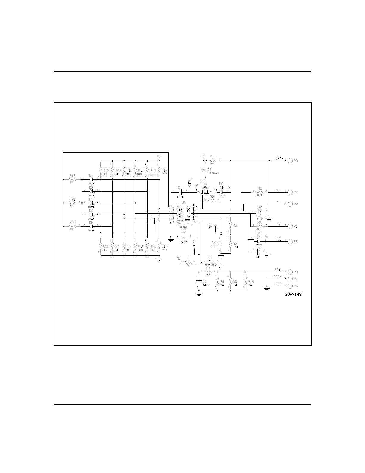
Appendix C: EV2050/H Schematic

IMPORTANT NOTICE AND DISCLAIMER
TI PROVIDES TECHNICAL AND RELIABILITY DATA (INCLUDING DATASHEETS), DESIGN RESOURCES (INCLUDING REFERENCE
DESIGNS), APPLICATION OR OTHER DESIGN ADVICE, WEB TOOLS, SAFETY INFORMATION, AND OTHER RESOURCES “AS IS”
AND WITH ALL FAULTS, AND DISCLAIMS ALL WARRANTIES, EXPRESS AND IMPLIED, INCLUDING WITHOUT LIMITATION ANY
IMPLIED WARRANTIES OF MERCHANTABILITY, FITNESS FOR A PARTICULAR PURPOSE OR NON-INFRINGEMENT OF THIRD
PARTY INTELLECTUAL PROPERTY RIGHTS.
These resources are intended for skilled developers designing with TI products. You are solely responsible for (1) selecting the appropriate
TI products for your application, (2) designing, validating and testing your application, and (3) ensuring your application meets applicable
standards, and any other safety, security, or other requirements. These resources are subject to change without notice. TI grants you
permission to use these resources only for development of an application that uses the TI products described in the resource. Other
reproduction and display of these resources is prohibited. No license is granted to any other TI intellectual property right or to any third
party intellectual property right. TI disclaims responsibility for, and you will fully indemnify TI and its representatives against, any claims,
damages, costs, losses, and liabilities arising out of your use of these resources.
TI’s products are provided subject to TI’s Terms of Sale (www.ti.com/legal/termsofsale.html) or other applicable terms available either on
ti.com or provided in conjunction with such TI products. TI’s provision of these resources does not expand or otherwise alter TI’s applicable
warranties or warranty disclaimers for TI products.
Mailing Address: Texas Instruments, Post Office Box 655303, Dallas, Texas 75265
Copyright © 2020, Texas Instruments Incorporated
Table of contents


