MPS mEZDPD4506A User manual

User Guide
mEZDPD4506A Evaluation Kit (PKT-mEZDPD4506A)

USER GUIDE –mEZDPD4506A EVALUATION KIT (PKT-mEZDPD4506A)
mEZDPD4506A Evaluation Kit User Guide Rev 1.0 MonolithicPower.com 1
5/16/2019 MPS Proprietary Information. Patent Protected. Unauthorized Photocopy and Duplication Prohibited.
© 2019 MPS. All Rights Reserved.
Table of Contents
Overview .................................................................................................................................................................. 2
Introduction.............................................................................................................................................................. 2
Kit Contents............................................................................................................................................................. 2
Features and Benefits............................................................................................................................................ 3
Kit Specifications..................................................................................................................................................... 3
Section 1. Hardware Specifications..................................................................................................................... 4
1.1 Personal Computer Requirements................................................................................................................ 4
1.2 EVmEZDPD4506A-00A Specifications......................................................................................................... 4
1.3 EVKT-USBI2C-02 Specifications................................................................................................................... 4
Section 2. Software Requirements ...................................................................................................................... 5
2.1 Software Installation ........................................................................................................................................ 5
Section 3. Evaluation Kit Test Set-Up ................................................................................................................. 6
3.1 Hardware Set-Up.............................................................................................................................................. 6
3.2 Powering Up the EVB...................................................................................................................................... 6
3.3 Software Set-Up............................................................................................................................................... 6
3.4 Device Programming Instructions.................................................................................................................. 9
3.5 Troubleshooting Tips..................................................................................................................................... 11
Section 4. PMBUS Interface ............................................................................................................................... 13
Section 5. Ordering Information.......................................................................................................................... 13
USER GUIDE –mEZDPD4506A EVALUATION KIT (PKT-mEZDPD4506A)
mEZDPD4506A Evaluation Kit User Guide Rev 1.0 MonolithicPower.com 2
5/16/2019 MPS Proprietary Information. Patent Protected. Unauthorized Photocopy and Duplication Prohibited.
© 2019 MPS. All Rights Reserved.
Overview
Introduction
The PKT-mEZDPD4506A is an evaluation kit for the mEZDPD4506A. The mEZDPD4506A is a PCB-
based, high-frequency, synchronous, rectified step-down module with a PMBus interface. The
mEZDPD4506A offers a complete power solution that achieves up to 6A continuous output current with
excellent load and line regulation over a wide input voltage range. MPS’s proprietary, multi-phase
constant-on-time (MCOT) control provides ultra-fast transient response and simple loop compensation.
This kit allows for quick evaluation and module configurations through the PMBus interface.
Kit Contents
PKT-mEZDPD4506A kit contents (items listed below can be ordered separately, and the GUI installation
file and supplemental documents can be downloaded from the MPS website):
#
Part Number
Item
Quantity
1
EVmEZDPD4506A-00A
mEZDPD4506A evaluation board
1
2
EVKT-USBI2C-02
Includes one USB to PMBus communication interface
device, one USB Male A to B cable, one 10-pin ribbon
cable, one 3-pin ribbon cable
1
3
mEZDPD4506A-0001
mEZDPD4506A module with default configuration
1
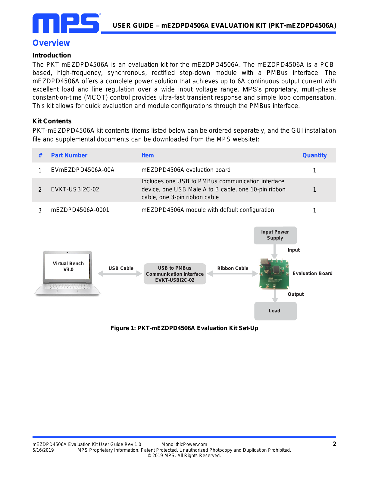
Figure 1: PKT-mEZDPD4506A Evaluation Kit Set-Up
Input Power
Supply
Input
Output
Load
USB
Cable
Ribbon Cable
Evaluation
Board
Virtual Bench
V3.0
USB to PMBus
Communication Interface
EVKT-USBI2C-02

USER GUIDE –mEZDPD4506A EVALUATION KIT (PKT-mEZDPD4506A)
mEZDPD4506A Evaluation Kit User Guide Rev 1.0 MonolithicPower.com 3
5/16/2019 MPS Proprietary Information. Patent Protected. Unauthorized Photocopy and Duplication Prohibited.
© 2019 MPS. All Rights Reserved.
Features and Benefits
The mEZDPD4506A is highly customizable. Users can program the power module via the MPS PMBus
and multi-time programming (MTP) memory.
Values written to the registers via PMBus will NOT be retained once the module is powered down
unless they are written into the MTP memory.
To write to the MTP memory, the input voltage must be greater than 8V.
Key programmable features: PMBus
Switching frequency
Operation mode –AAM or CCM
Output voltage
Soft-start time
Fault threshold
Kit Specifications
Features
Specification
Input Voltage
4V to 45V
Output Voltage
0.6V to 24V (default: 3.3V)
Maximum Output Current
10A continuous, 12A peak
Default Switching Frequency
600kHz
Operating Systems Supported
Windows 7 or later
System Requirements
Minimum 15.6MB free
EVB Size (LxW)
6.4cmx6.4cm
USER GUIDE –mEZDPD4506A EVALUATION KIT (PKT-mEZDPD4506A)
mEZDPD4506A Evaluation Kit User Guide Rev 1.0 MonolithicPower.com 4
5/16/2019 MPS Proprietary Information. Patent Protected. Unauthorized Photocopy and Duplication Prohibited.
© 2019 MPS. All Rights Reserved.
Section 1. Hardware Specifications
1.1 Personal Computer Requirements
The following requirements must be met to use the PKT-mEZDPD4506A:
Operating system of Windows XP, 7, or later
Net framework 4.0
PC with a minimum of one available USB port
At least 15.6MB of free space
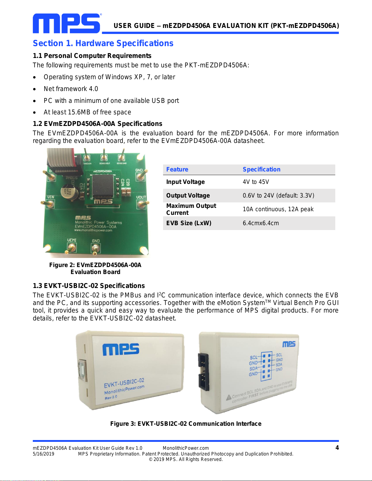
1.2 EVmEZDPD4506A-00A Specifications
The EVmEZDPD4506A-00A is the evaluation board for the mEZDPD4506A. For more information
regarding the evaluation board, refer to the EVmEZDPD4506A-00A datasheet.
Feature
Specification
Input Voltage
4V to 45V
Output Voltage
0.6V to 24V (default: 3.3V)
Maximum Output
Current
10A continuous, 12A peak
EVB Size (LxW)
6.4cmx6.4cm
Figure 2: EVmEZDPD4506A-00A
Evaluation Board
1.3 EVKT-USBI2C-02 Specifications
The EVKT-USBI2C-02 is the PMBus and I2C communication interface device, which connects the EVB
and the PC, and its supporting accessories. Together with the eMotion SystemTM Virtual Bench Pro GUI
tool, it provides a quick and easy way to evaluate the performance of MPS digital products. For more
details, refer to the EVKT-USBI2C-02 datasheet.
Figure 3: EVKT-USBI2C-02 Communication Interface
USER GUIDE –mEZDPD4506A EVALUATION KIT (PKT-mEZDPD4506A)
mEZDPD4506A Evaluation Kit User Guide Rev 1.0 MonolithicPower.com 5
5/16/2019 MPS Proprietary Information. Patent Protected. Unauthorized Photocopy and Duplication Prohibited.
© 2019 MPS. All Rights Reserved.
Section 2. Software Requirements
2.1 Software Installation
The eMotion SystemTM Virtual Bench Pro GUI tool provides an easy way to access the registers, program
the MTP memory, and monitor the key parameters of MPS power modules. Follow the instructions below
to install the software:
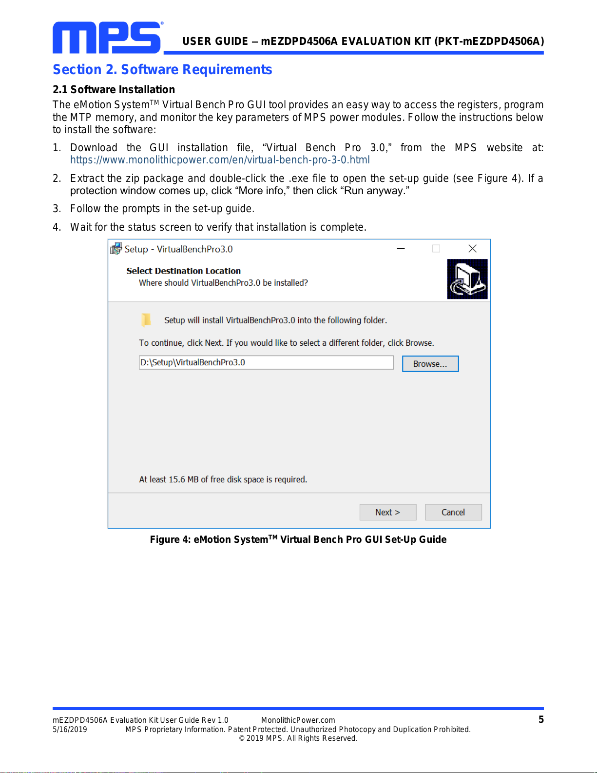
1. Download the GUI installation file, “Virtual Bench Pro 3.0,” from the MPS website at:
https://www.monolithicpower.com/en/virtual-bench-pro-3-0.html
2. Extract the zip package and double-click the .exe file to open the set-up guide (see Figure 4). If a
protection window comes up, click “More info,” then click “Run anyway.”
3. Follow the prompts in the set-up guide.
4. Wait for the status screen to verify that installation is complete.
Figure 4: eMotion SystemTM Virtual Bench Pro GUI Set-Up Guide
USER GUIDE –mEZDPD4506A EVALUATION KIT (PKT-mEZDPD4506A)
mEZDPD4506A Evaluation Kit User Guide Rev 1.0 MonolithicPower.com 6
5/16/2019 MPS Proprietary Information. Patent Protected. Unauthorized Photocopy and Duplication Prohibited.
© 2019 MPS. All Rights Reserved.
Section 3. Evaluation Kit Test Set-Up
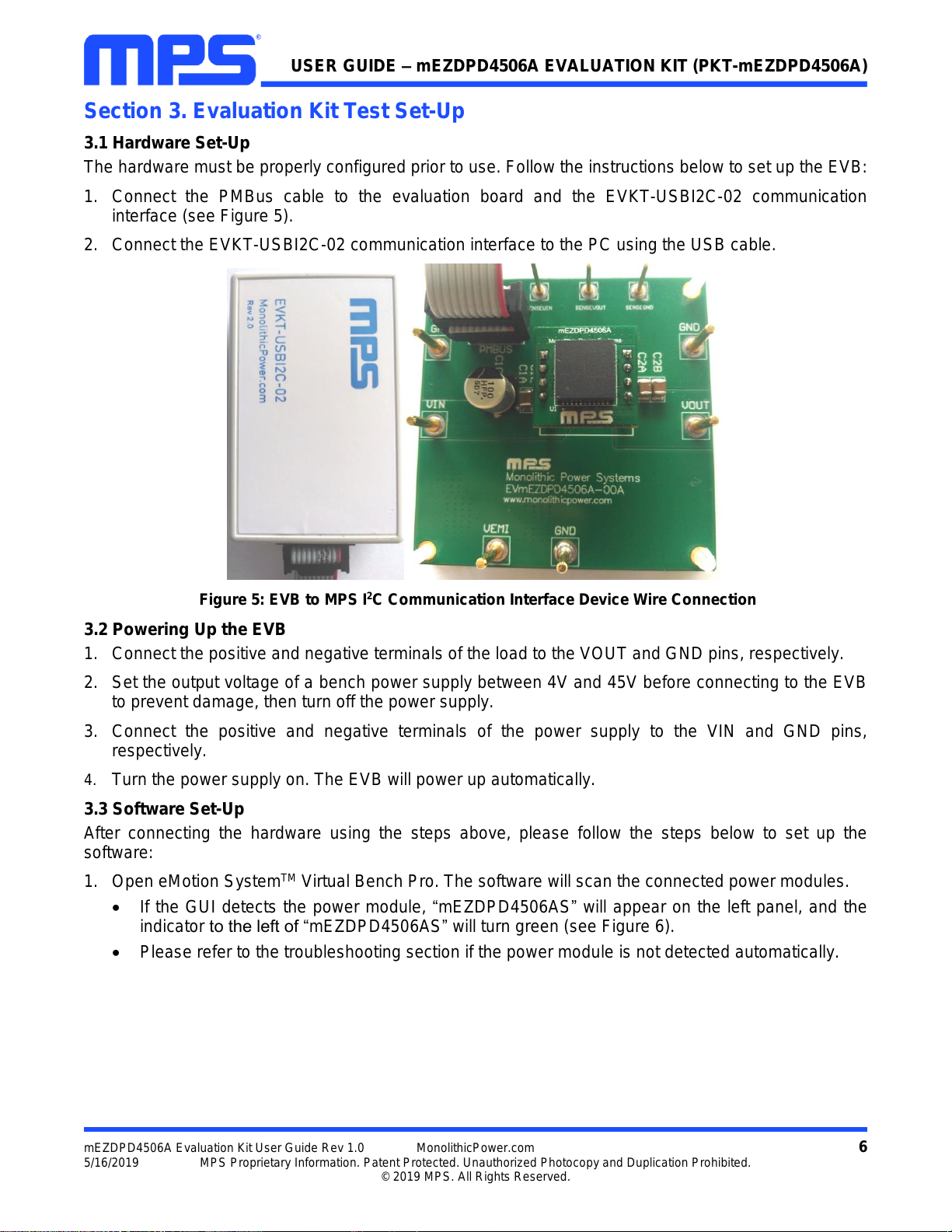
3.1 Hardware Set-Up
The hardware must be properly configured prior to use. Follow the instructions below to set up the EVB:
1. Connect the PMBus cable to the evaluation board and the EVKT-USBI2C-02 communication
interface (see Figure 5).
2. Connect the EVKT-USBI2C-02 communication interface to the PC using the USB cable.
Figure 5: EVB to MPS I2C Communication Interface Device Wire Connection
3.2 Powering Up the EVB
1. Connect the positive and negative terminals of the load to the VOUT and GND pins, respectively.
2. Set the output voltage of a bench power supply between 4V and 45V before connecting to the EVB
to prevent damage, then turn off the power supply.
3. Connect the positive and negative terminals of the power supply to the VIN and GND pins,
respectively.
4. Turn the power supply on. The EVB will power up automatically.
3.3 Software Set-Up
After connecting the hardware using the steps above, please follow the steps below to set up the
software:
1. Open eMotion SystemTM Virtual Bench Pro. The software will scan the connected power modules.
If the GUI detects the power module, “mEZDPD4506AS”will appear on the left panel, and the
indicator to the left of “mEZDPD4506AS”will turn green (see Figure 6).
Please refer to the troubleshooting section if the power module is not detected automatically.
USER GUIDE –mEZDPD4506A EVALUATION KIT (PKT-mEZDPD4506A)
mEZDPD4506A Evaluation Kit User Guide Rev 1.0 MonolithicPower.com 7
5/16/2019 MPS Proprietary Information. Patent Protected. Unauthorized Photocopy and Duplication Prohibited.
© 2019 MPS. All Rights Reserved.
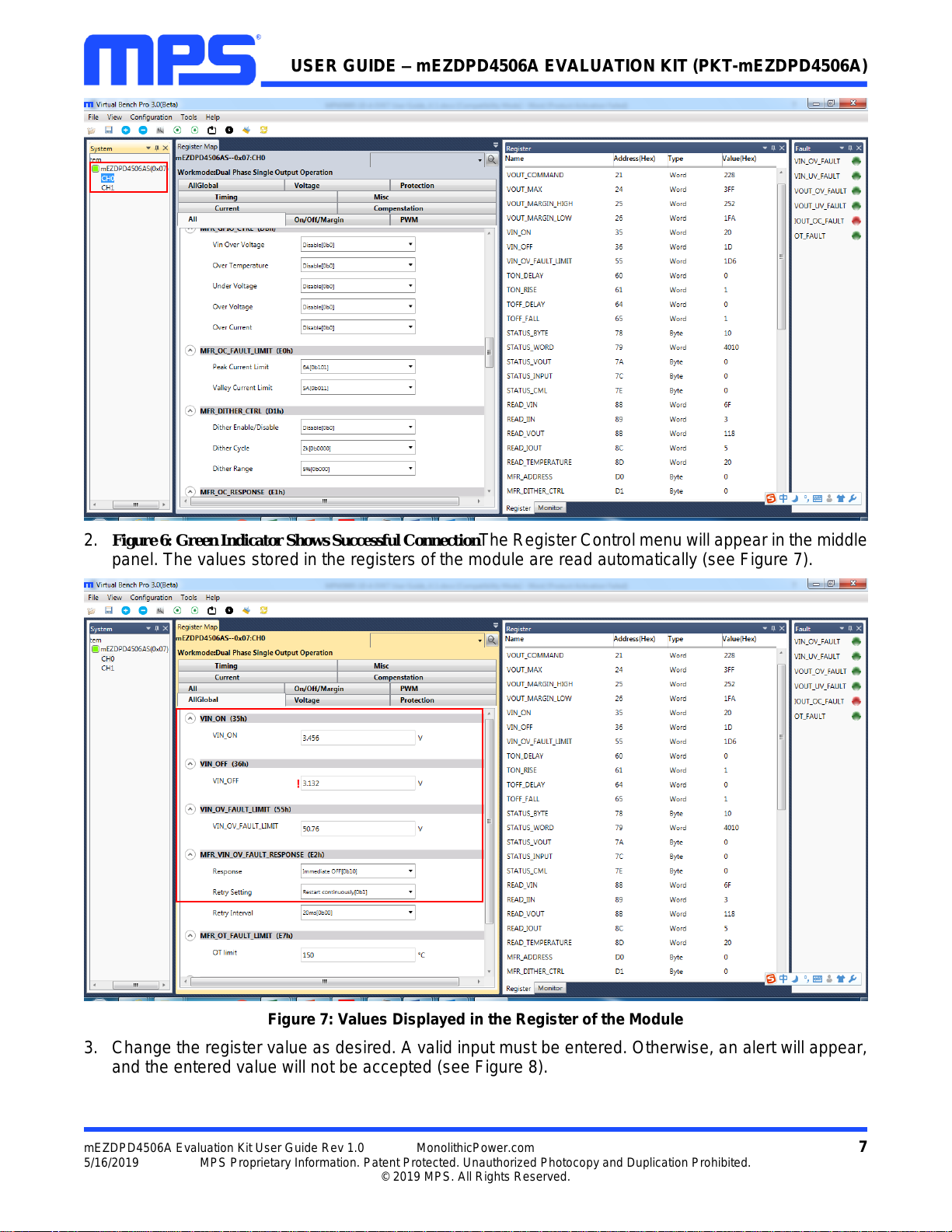
2. Figure 6: Green Indicator Shows Successful ConnectionThe Register Control menu will appear in the middle
panel. The values stored in the registers of the module are read automatically (see Figure 7).
Figure 7: Values Displayed in the Register of the Module
3. Change the register value as desired. A valid input must be entered. Otherwise, an alert will appear,
and the entered value will not be accepted (see Figure 8).
USER GUIDE –mEZDPD4506A EVALUATION KIT (PKT-mEZDPD4506A)
mEZDPD4506A Evaluation Kit User Guide Rev 1.0 MonolithicPower.com 8
5/16/2019 MPS Proprietary Information. Patent Protected. Unauthorized Photocopy and Duplication Prohibited.
© 2019 MPS. All Rights Reserved.
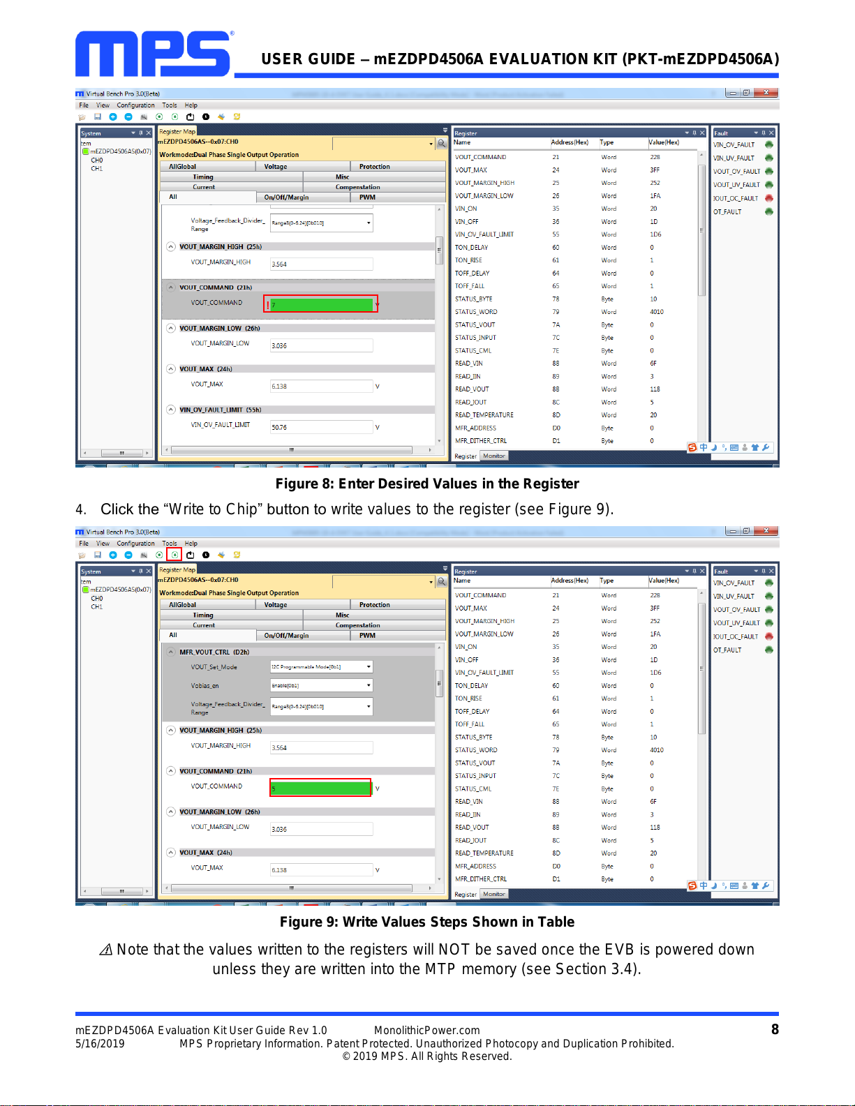
Figure 8: Enter Desired Values in the Register
4. Click the “Write to Chip” button to write values to the register (see Figure 9).
Figure 9: Write Values Steps Shown in Table
Note that the values written to the registers will NOT be saved once the EVB is powered down
unless they are written into the MTP memory (see Section 3.4).

USER GUIDE –mEZDPD4506A EVALUATION KIT (PKT-mEZDPD4506A)
mEZDPD4506A Evaluation Kit User Guide Rev 1.0 MonolithicPower.com 9
5/16/2019 MPS Proprietary Information. Patent Protected. Unauthorized Photocopy and Duplication Prohibited.
© 2019 MPS. All Rights Reserved.
3.4 Device Programming Instructions
The MTP memory of mEZDPD4506A can be custom programmed. Follow the instructions below to create
and export customized configurations:
1. Connect the EVB to a PC following the steps in Section 3.3.
2. Set the register values as desired, and upload them into the registers (steps 3-4 in Section 3.3).
3. Increase the input voltage of the EVB to 8V to 45V.
4. Click the “Write to MTP”button, and wait until the writing action is completed (see Figure 10).
5. Turn off the power supply to the EVB, wait 3 seconds, and turn it on for the new configuration to take
effect.
Figure 10: Write to the MTP Memory
USER GUIDE –mEZDPD4506A EVALUATION KIT (PKT-mEZDPD4506A)
mEZDPD4506A Evaluation Kit User Guide Rev 1.0 MonolithicPower.com 10
5/16/2019 MPS Proprietary Information. Patent Protected. Unauthorized Photocopy and Duplication Prohibited.
© 2019 MPS. All Rights Reserved.
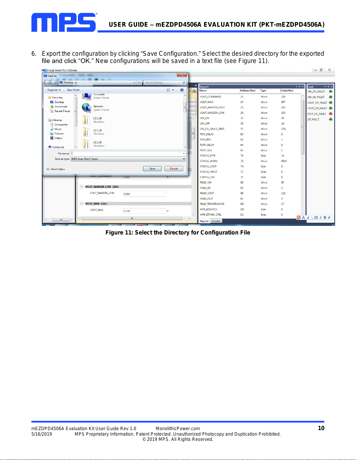
6. Export the configuration by clicking “Save Configuration.”Select the desired directory for the exported
file and click “OK.”New configurations will be saved in a text file (see Figure 11).
Figure 11: Select the Directory for Configuration File
USER GUIDE –mEZDPD4506A EVALUATION KIT (PKT-mEZDPD4506A)
mEZDPD4506A Evaluation Kit User Guide Rev 1.0 MonolithicPower.com 11
5/16/2019 MPS Proprietary Information. Patent Protected. Unauthorized Photocopy and Duplication Prohibited.
© 2019 MPS. All Rights Reserved.
3.5Troubleshooting Tips
Note: USBI2C-02 and USBI2C-01 drivers are not compatible. USBI2C-02 uses USBXpress and USBI2C-
01 uses Cyusb3. USBI2C-02 is the recommended device for MPS PMBus and I2C.
EVKT-USBI2C-01
If the USBI2C-01 driver is not properly installed, manual
installation is required. Follow the steps below.
1. Open the Device Manager and select “Update Driver
Software”(see Figure 12).
2. Click “Browse My Computer for Driver Software,” find
the downloaded driver, and install.
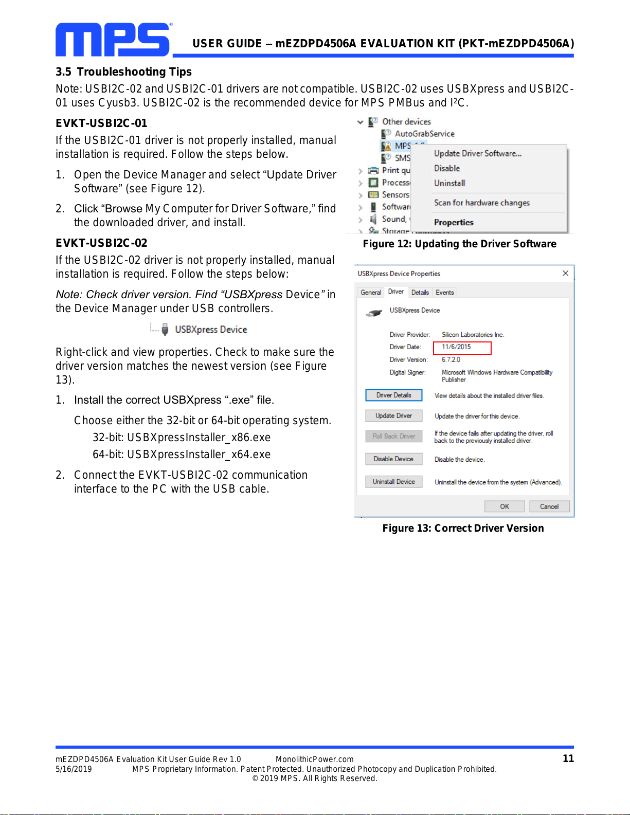
EVKT-USBI2C-02
If the USBI2C-02 driver is not properly installed, manual
installation is required. Follow the steps below:
Note: Check driver version. Find “USBXpress Device”in
the Device Manager under USB controllers.
Right-click and view properties. Check to make sure the
driver version matches the newest version (see Figure
13).
1. Install the correct USBXpress “.exe” file.
Choose either the 32-bit or 64-bit operating system.
32-bit: USBXpressInstaller_x86.exe
64-bit: USBXpressInstaller_x64.exe
2. Connect the EVKT-USBI2C-02 communication
interface to the PC with the USB cable.
Figure 13: Correct Driver Version
Figure 12: Updating the Driver Software

USER GUIDE –mEZDPD4506A EVALUATION KIT (PKT-mEZDPD4506A)
mEZDPD4506A Evaluation Kit User Guide Rev 1.0 MonolithicPower.com 12
5/16/2019 MPS Proprietary Information. Patent Protected. Unauthorized Photocopy and Duplication Prohibited.
© 2019 MPS. All Rights Reserved.
EVB Connection Issue
If the power module cannot be automatically detected, follow the steps below to troubleshoot:
Click on “Tools”→ “PMBus Tool”→ “Scan,”then read the value of the slave (0x).
Right-click the “mEZDPD4506AS”on the left panel. Click “Change Chip Address”and enter the
value “slave(0x)” (see Figure 14). The module will be added manually.
Figure 14: Change the Chip Address and the Indicator Turns Green to Show Successful Connection
If the power module still is not be detected, check the connections between the EVB, communication
interface, and PC. Re-plug the USB into the computer and restart the GUI.
No Output Voltage
The mEZDPD4506A offers many protection features. If any of the protection functions are triggered, the
power module may latch off. The indicator on the right panel indicates the specific fault. A red indicator
signifies that a fault has been triggered. Refer to the mEZDPD4506A datasheet for details regarding
specific faults.

USER GUIDE –mEZDPD4506A EVALUATION KIT (PKT-mEZDPD4506A)
mEZDPD4506A Evaluation Kit User Guide Rev 1.0 MonolithicPower.com 13
5/16/2019 MPS Proprietary Information. Patent Protected. Unauthorized Photocopy and Duplication Prohibited.
© 2019 MPS. All Rights Reserved.
Section 4. PMBUS Interface
The power management bus (PMBus) is a two-wire, bidirectional serial interface, consisting of a data line
(SDA) and a clock line (SCL). The lines are externally pulled to a bus voltage when they are idle.
Connecting to the line, a master device generates the SCL signal and device address, and arranges the
communication sequence. It is based on the principles of I2C operation.
The mEZDPD4506A interface is a PMBus slave, which supports both the standard mode (100kHz) and
fast mode (400kHz and 1000KHz). The PMBus interface adds flexibility to the power supply solution.

USER GUIDE –mEZDPD4506A EVALUATION KIT (PKT-mEZDPD4506A)
mEZDPD4506A Evaluation Kit User Guide Rev 1.0 MonolithicPower.com 14
5/16/2019 MPS Proprietary Information. Patent Protected. Unauthorized Photocopy and Duplication Prohibited.
© 2019 MPS. All Rights Reserved.
Section 5. Ordering Information
The components of the evaluation kit can be ordered separately. The GUI installation file and
supplemental documents can be downloaded from the MPS website.
Part Number
Description
PKT-mEZDPD4506A
Complete evaluation kit
Contents of PKT-mEZDPD4506A
EVmEZDPD4506A-00A
mEZDPD4506A evaluation board
EVKT-USBI2C-02
Includes one USB to PMBus communication interface device, one
USB Male A to B cable, one 10-pin ribbon cable, and one 3-pin ribbon
cable
mEZDPD4506A-0001
mEZDPD4506A module(DIP) with default configuration
Order directly from MonolithicPower.com or our distributors.
This manual suits for next models
1
Table of contents
Other MPS Motherboard manuals

MPS
MPS MagAlpha EVMA Q-00A Series Operating instructions

MPS
MPS EV6001DN-00D User manual

MPS
MPS EVKT6515 User manual

MPS
MPS EV3209DJ-00A User manual

MPS
MPS EV2696A-Q-00B User manual

MPS
MPS EVmEZDPD3603A-00A User manual

MPS
MPS EV8042DF-00B User manual

MPS
MPS EVBL2166-D-00A User manual

MPS
MPS EV20045DQ-00A User manual

MPS
MPS EVHF900-P-00A User manual

MPS
MPS EVKT-MP8833 User manual

MPS
MPS EVKT-MACOM User manual

MPS
MPS MP2663 User manual

MPS
MPS EV2483DQ-00C User manual

MPS
MPS EV2605DQ-00B User manual

MPS
MPS EVKT-1203 User manual

MPS
MPS EVHR2000-S-00A User manual

MPS
MPS EV28163-Q-00A User manual

MPS
MPS EV2759-Q-00A User manual

MPS
MPS EV6536-U-00A User manual


