Bender ISOSCAN W Series User manual

ISOSCAN® EDS440 and EDS441
Insulation fault locator to locate insulation faults
in ungrounded DC, AC and three-phase power supplies
EDS44x_D00201_10_M_XXEN/11.2023

2 EDS44x_D 2 1_1 _M_XXEN/11.2 23

ISOSCAN® EDS44 and EDS441
Table of contents
1General information...........................................................................................7
1.1 How to use the manual.................................................................................................................................7
1.2 Indication of important instructions and information.......................................................................7
1.3 Signs and symbols...........................................................................................................................................7
1.4 Service and Support....................................................................................................................................... 7
1.5 Training courses and seminars...................................................................................................................8
1.6 Delivery conditions......................................................................................................................................... 8
1.7 Inspection, transport and storage.............................................................................................................8
1.8 Warranty and liability.....................................................................................................................................8
1.9 Disposal of Bender devices..........................................................................................................................9
1.1 Safety.................................................................................................................................................................... 9
2Function.............................................................................................................10
2.1 Intended use................................................................................................................................................... 1
2.2 Features.............................................................................................................................................................1
2.2.1 Areas of application..................................................................................................................................... 1
2.2.2 Standards..........................................................................................................................................................1
2.2.3 System variants.............................................................................................................................................. 11
2.2.4 System properties......................................................................................................................................... 11
2.2.5 Compatibility...................................................................................................................................................12
2.3 Operating principle of the EDS system................................................................................................ 13
2.4 Schematic diagram of an EDS system...................................................................................................15
3Device overview............................................................................................... 16
3.1 External dimensions of EDS44… and IOM441-S............................................................................... 16
3.2 View and connections of EDS44…-L.....................................................................................................17
3.3 View and connections of EDS44…-S.....................................................................................................18
4ounting...........................................................................................................19
4.1 General information..................................................................................................................................... 19
4.2 Installation clearances................................................................................................................................. 19
4.3 Screw mounting............................................................................................................................................ 2
4.4 DIN rail mounting......................................................................................................................................... 21
4.5 Connection of the BB bus..........................................................................................................................21
4.6 Connection to the voltage supply..........................................................................................................22
4.7 Connection of the X1 interface (I1, I2, A, B, M+, ...).......................................................................... 22
EDS44x_D 2 1_1 _M_XXEN/11.2 23 3

Table of contents
4.8 Connection of the relays............................................................................................................................ 23
4.9 BS bus termination....................................................................................................................................... 23
4.1 Connection of the X2 interface (k1-12/l1-12).....................................................................................24
4.1 .1 Connection of CTAC… series measuring current transformers...................................................24
4.1 .2 Connection of measuring current transformer CTBC… to EDS441-LAB-4...............................26
4.1 .3 Connection of CTAF…SET series measuring current transformers to EDS44 -LAF-4..........27
4.11 Connection to a 3(N)AC system.............................................................................................................. 28
4.12 Connection to an AC system....................................................................................................................29
4.13 Connection to a DC system...................................................................................................................... 3
4.14 Connection example: ISOMETER® iso685-D-P, EDS44 -S, IOM441-S and EDS44 -L.............31
5Display and alarm messages...........................................................................32
5.1 Display elements EDS44…-S.................................................................................................................... 32
5.2 Operating and display elements EDS44…-L...................................................................................... 32
5.3 Standard display in operating mode.....................................................................................................33
5.3.1 Standard display EDS44…-S..................................................................................................................... 33
5.3.2 Standard display EDS44…-L..................................................................................................................... 33
5.4 Alarm messages.............................................................................................................................................34
5.4.1 Insulation fault (ALARM IΔL).......................................................................................................................34
5.4.2 Residual current exceeded (ALARM IΔn)............................................................................................... 35
5.4.3 Connection fault of the current transformers....................................................................................35
5.4.4 Device error, BB bus error..........................................................................................................................36
5.4.5 Device error, failure BS bus master........................................................................................................ 37
5.4.6 Error message................................................................................................................................................. 37
5.4.7 Acoustic alarm message.............................................................................................................................37
6Commissioning................................................................................................. 38
6.1 Requirements for reliable insulation fault location..........................................................................38
6.2 Before switching on..................................................................................................................................... 38
6.3 Switching on................................................................................................................................................... 39
6.4 Steps for commissioning ISOMETER® and EDS..................................................................................39
6.5 Periodic verification......................................................................................................................................4
7Device communication.................................................................................... 41
7.1 RS-485 interface.............................................................................................................................................41
7.2 Bender Sensor bus (BS bus)...................................................................................................................... 41
7.3 Modbus RTU....................................................................................................................................................42
8Operation.......................................................................................................... 43
4 EDS44x_D 2 1_1 _M_XXEN/11.2 23

ISOSCAN® EDS44 and EDS441
8.1 Reading out and setting the BS address..............................................................................................43
8.1.1 Reading out a BS address.......................................................................................................................... 43
8.1.2 Setting a BS address.................................................................................................................................... 44
8.1.3 Extended address range (offset = 8 )...................................................................................................46
8.2 Display and change of transmission protocols..................................................................................47
8.2.1 Displaying the current transmission protocol....................................................................................47
8.2.2 Changing the transmission protocol..................................................................................................... 48
8.3 Resetting saved alarm messages (RESET button)............................................................................. 48
8.4 Deactivating the buzzer (EDS44…-L only).......................................................................................... 48
8.5 Running a test (TEST button)................................................................................................................... 48
9Settings..............................................................................................................50
9.1 EDS settings on the ISOMETER®.............................................................................................................. 5
9.1.1 Locating current injector settings...........................................................................................................5
9.1.2 Trigger function............................................................................................................................................. 51
9.1.3 Fault memory..................................................................................................................................................51
9.2 Settings of inputs and outputs of the EDS44…-L............................................................................ 51
9.2.1 Digital inputs of the EDS44…-L (I1, I2)................................................................................................. 51
9.2.2 Digital outputs of the EDS44…-L........................................................................................................... 52
9.3 Factory settings..............................................................................................................................................54
10 Alarm messages................................................................................................56
11 Diagrams........................................................................................................... 57
11.1 Response sensitivity curves.......................................................................................................................57
11.1.1 Characteristic curves EDS44 for 3AC systems..................................................................................58
11.1.2 Characteristic curves EDS44 for AC systems.................................................................................... 6
11.1.3 Characteristic curve of EDS44 for low voltages in DC, AC and 3NAC systems..................... 61
11.1.4 Characteristic curves EDS44 for DC systems.................................................................................... 62
11.1.5 Characteristic curves EDS441 for AC systems.................................................................................... 65
11.1.6 Characteristic curves EDS441 for DC systems.................................................................................... 66
11.1.7 Characteristic curves of EDS441-LAB for AC systems......................................................................68
11.1.8 Characteristic curves EDS441-LAB for DC systems........................................................................... 69
11.1.9 Response values of EDS44 -LAF for DC systems.............................................................................. 71
11.1.1 Response values of EDS44 -LAF for AC systems...............................................................................71
11.2 Fault curve EDS44 and EDS441.............................................................................................................72
12 Technical data...................................................................................................73
12.1 Technical data ISOSCAN® EDS44 and EDS441................................................................................. 73
EDS44x_D 2 1_1 _M_XXEN/11.2 23 5

Table of contents
12.2 Standards and certifications..................................................................................................................... 79
12.3 Ordering data..................................................................................................................................................8
12.3.1 Insulation fault locators.............................................................................................................................. 8
12.3.2 Accessories.......................................................................................................................................................8
12.3.3 Measuring current transformers..............................................................................................................81
12.4 Change history............................................................................................................................................... 83
6 EDS44x_D 2 1_1 _M_XXEN/11.2 23

ISOSCAN® EDS44 and EDS441
1 General information
1.1 How to use the manual
ADVICE
This manual is intended for qualified personnel working in electrical engineering and electronics!
Part of the device documentation in addition to this manual is the enclosed supplement ‘Safety
instructions for Bender products’.
ADVICE
Read the operating manual before mounting, connecting and commissioning the device. Keep the
manual within easy reach for future reference.
1.2 Indication of important instructions and information
DANGER
Indicates a high risk of danger that will result in death or serious injury if not avoided.
WARNING
Indicates a medium risk of danger that can lead to death or serious injury if not avoided.
CAUTION
Indicates a low-level risk that can result in minor or moderate injury or damage to property if not
avoided.
ADVICE
Indicates important facts that do not result in immediate injuries. They can lead to malfunctions if the
device is handled incorrectly.
Information can help to optimise the use of the product.
1.3 Signs and symbols
Disposal Protect from moisture Protect from dust
Temperature range Recycling RoHS directives
1.4 Service and Support
Information and contact details about customer service, repair service or field service for Bender devices are
available on the following website: Fast assistance | Bender GmbH & Co. KG.
EDS44x_D 2 1_1 _M_XXEN/11.2 23 7

General information
1.5 Training courses and seminars
Regular face-to-face or online seminars for customers and other interested parties:
www.bender.de > know-how > seminars.
1.6 Delivery conditions
The conditions of sale and delivery set out by Bender GmbH & Co. KG apply. These can be obtained in printed
or electronic format.
The following applies to software products:
Die Elektroindustrie
‘Software clause in respect of the licensing of standard software as part of deliveries,
modifications and changes to general delivery conditions for products and services in the
electrical industry’
1.7 Inspection, transport and storage
Check the shipping and device packaging for transport damage and scope of delivery. In the event of
complaints, the company must be notified immediately, see ‘www.bender.de > service & support.’.
The following must be observed when storing the devices:
1.8 Warranty and liability
Warranty and liability claims for personal injury and property damage are excluded in the case of:
•Improper use of the device.
•Incorrect mounting, commissioning, operation and maintenance of the device.
•Failure to observe the instructions in this operating manual regarding transport, commissioning, operation
and maintenance of the device.
•Unauthorised changes to the device made by parties other than the manufacturer.
•Non-observance of technical data.
•Repairs carried out incorrectly.
•The use of accessories or spare parts that are not provided, approved or recommended by the
manufacturer.
•Catastrophes caused by external influences and force majeure.
•Mounting and installation with device combinations not approved or recommended by the manufacturer.
This operating manual and the enclosed safety instructions must be observed by all persons working with the
device. Furthermore, the rules and regulations that apply for accident prevention at the place of use must be
observed.
8 EDS44x_D 2 1_1 _M_XXEN/11.2 23

ISOSCAN® EDS44 and EDS441
1.9 Disposal of Bender devices
Abide by the national regulations and laws governing the disposal of this device.
For more information on the disposal of Bender devices, refer to
www.bender.de > service & support.
1.10 Safety
If the device is used outside the Federal Republic of Germany, the applicable local standards and regulations
must be complied with. In Europe, the European standard EN 5 11 applies.
DANGER Risk of fatal injury due to electric shock!
Touching live parts of the system carries the risk of:
•Risk of electrocution due to electric shock
•Damage to the electrical installation
•Destruction of the device
Before installing the device and before working on its connections, make sure that the installation
has been de-energised. The rules for working on electrical systems must be observed.
EDS44x_D 2 1_1 _M_XXEN/11.2 23 9

Function
2 Function
2.1 Intended use
The insulation fault locators ISOSCAN® EDS44 and EDS441 are used to locate insulation faults in unearthed
DC, AC and three-phase power supply systems (IT systems). Depending on the locating current injector, AC
and three-phase systems can be monitored within the range from AC 42 to 1 V; DC systems, within the
range from DC 24 to 15 V.
An AC residual current can be indicated in these ranges:
•EDS44 : 42…1 Hz, .1…2 A
•EDS441: 42…6 Hz, .1…2 A
An EDS system (insulation fault location system) consists of an EDS44x insulation fault locator and a locating
current injector. EDS44… insulation fault locators detect locating current signals generated by the locating
current injector via measuring current transformers and evaluate them accordingly.
Intended use also implies
•the observation of all information in the operating manual and
•compliance with test intervals.
In order to meet the requirements of the applicable standards, customised parameter settings must be made
on the equipment in order to adapt it to local equipment and operating conditions. Please heed the limits of
the range of application indicated in the technical data.
Do not make any unauthorised changes to the device. Only use spare parts and optional accessories sold or
recommended by the manufacturer.
The messages of the device must be perceptible even if it is installed in a control cabinet.
The devices is not designed for use in residential areas and may not provide sufficient protection for radio
reception there.
Any other use than that described in this manual is regarded as improper.
2.2 Features
2.2.1 Areas of application
•Insulation fault location in AC, 3(N)AC and DC IT systems
•Main circuits and control circuits in industrial plants and ships
•Diode-decoupled DC IT systems in power plants
•Systems for medical locations
2.2.2 Standards
The standard for unearthed power supplies (IT systems)
DIN VDE 0 00-4 0 (VDE 0 00- 4 0):20 8- 0 (IEC 60364-4-4 :2005, modified + A :20 7, modified)
requires that the first insulation fault is to be eliminated with the shortest practicable delay. EDS systems
enable fast localisation of this insulation fault.
1 EDS44x_D 2 1_1 _M_XXEN/11.2 23

ISOSCAN® EDS44 and EDS441
2.2.3 System variants
The devices ISOSCAN® EDS44 and EDS441 differ depending on their response sensitivity. EDS44 is suitable
for main circuits. EDS441 can be used in control circuits and in circuits in medical locations.
-L -S -LAB-4 -LAF-4
EDS440 Channel LED
BS bus
IΔL = 2…10 mA
Main circuits
Digital in uts and
out uts
No channel LED
BB bus
IΔL = 2…10 mA
Main circuits
No internal voltage
su ly
Channel LED
BS bus
IΔL = 10 mA 2)
Main circuits
Digital in uts and
out uts
EDS441 Channel LED
BS-Bus
IΔL = 0.2…1 mA
Control circuits
Digital in uts and
out uts
No channel LED
BB bus
IΔL = 0.2…1 mA
Control circuits
No internal voltage
su ly
Channel LED
BS-Bus
IΔL = 0.2…1 mA 1)
Control circuits
W…AB current
transformers
Digital in uts and
out uts
1) High response sensitivity with large system leakage capacitances
2) In combination with CTAF...SET series measuring current transformers
2.2.4 System properties
■Universal system design
■Modular design, therefore easily adjustable to the given circumstances
■Measuring current transformers available in various sizes and versions
■CT connection monitoring
■Twelve measuring channels for series W…, WR…, WS… measuring current transformers
■Optional extension by twelve relay channels
■Fault memory behaviour selectable
■Up to 5 EDS insulation fault locators in the system, 6 measuring channels
■Response sensitivity:
– EDS44 …: 2…1 mA
– EDS441…: .2…1 mA
■AC residual current measurement with configurable response value
■Two alarm relays with one n/o contact each
■n/o or n/c operation selectable
■External test/reset button
■Central display of faulty outgoing circuits
■Serial interface RS-485, BS bus address range 2…79
■Connection to higher-level control and visualisation systems possible.
EDS44x_D 2 1_1 _M_XXEN/11.2 23 11

Function
2.2.5 Compatibility
Legende
BS bus Full compatibility, communication via BS bus
BB bus Full compatibility, communication via BB bus
◊ Full compatibility, no communication possible
#Limited compatibility + communication via BS bus
Limited display of messages on the device.
Limited parameterisation via the device possible.
! Limited compatibility + communication via BS bus
Display of all messages on the device.
No parameter setting via the device possible.
Combination of insulation fault locators
Device EDS440-L EDS440-S EDS441-L EDS441-S EDS441-LAB EDS440-LAF
EDS440-L BS bus ◊
EDS440-S ◊ BB bus
EDS441-L BS bus ◊
EDS441-S ◊ BB bus
EDS441-LAB BS bus
EDS441-LAF BS bus
EDS460/490L BS bus ◊
EDS460/490D BS bus ◊
EDS461/491L BS bus ◊
EDS461/491D BS bus ◊
EDS150 BS bus ◊
EDS151 BS bus ◊
EDS195P ◊◊◊◊
Current transformers and measuring clamps
Device Type EDS440-L /S EDS441-L /S EDS441-LAB EDS440-LAF
W…/WR…/
WS…
Type A ◊
W/WS 8000 Type A ◊ ◊
W…AB Type AB ◊
CTAS, CTAC Type A ◊
CTAS…/01,
CTAC…/01
Type A ◊
12 EDS44x_D 2 1_1 _M_XXEN/11.2 23

ISOSCAN® EDS44 and EDS441
Device Type EDS440-L /S EDS441-L /S EDS441-LAB EDS440-LAF
CTUB10 Type B ◊
CTAF…SET Type A ◊
Other Bender devices
Device EDS440-L EDS440-S EDS441-L EDS441-S EDS441-LAB EDS440-LAF
COM460 ! ! ! !
COM465 ! ! ! !
IOM441-S !!!!!!
CP700 ! ! ! !
MK 430 # #
IRDH575 # #
iso685-…-p BS bus BS bus BS bus BS bus BS bus BS bus
isoMED4 7 ◊
PGH183 ◊ ◊
PGH185 ◊ ◊
PGH186 ◊ ◊
2.3 Operating principle of the EDS system
When an insulation monitoring device detects an insulation fault, it starts the insulation fault location.
In the event of a first insulation fault, an undefined residual current flows in IT systems, which is primarily
defined by the system leakage capacitances and the value of the insulation fault. The basic idea of insulation
fault location is therefore to generate a defined locating current IL that flows through the insulation fault. The
locating current is driven by the system voltage and can be located in the faulty outgoing circuit using the
measuring current transformer.
The locating current is generated by the locating current injector. It is limited in amplitude and time. The
amplitude depends on the size of the existing insulation fault and the system voltage. It is limited depending
on the settings.
The locating current flows from the locating current injector via the live lines to the insulation fault location
taking the shortest route. From there, it flows through the insulation fault and the earth conductor back to the
locating current injector. This locating current pulse is detected by the measuring current transformers on the
insulation fault path and signalled by the connected insulation fault locator.
EDS44x_D 2 1_1 _M_XXEN/11.2 23 13

Function
Locating pulse pattern
x s
y s
x s
y s
The length of the pulse and pause intervals depends on the system conditions (RF, Ce).
For further information, refer to Bender Main Catalogue, chapter “Equipment for insulation fault location” at
https://www.bender.de/en/service-support/download-area/.
Measured value depending on the system leakage capacitance
The influence of system leakage capacitances may cause false indication of the locating current.
The locating current of the locating current injector is limited. Due to this limitation, the resistance of the
insulation fault may be lower than the value signalled by the indicated locating current.
Project planning
During project planning care must be taken that there are no system parts where the locating current can
cause harmful reactions even in unfavourable cases.
Symmetrical insulation faults
Under certain conditions, symmetrical insulation faults located downstream of the measuring current
transformer are not detected. Lowfrequency residual currents (e.g. caused by converters) may prevent
insulation faults from being detected if their frequency is identical or almost identical to the test pulse
frequency of the locating current injector.
Influence by other components
Components, loads or EMC influences within an IT system may interfere with the locating of insulation
faults. Thus, reliable localisation may not be possible under all circumstances or false tripping may occur.
14 EDS44x_D 2 1_1 _M_XXEN/11.2 23

ISOSCAN® EDS44 and EDS441
2.4 Schematic diagram of an EDS system
Un
L1
L2
PE
RF
IL
IL
A1/+
A2/-
21 22 24
11 12 14
L1/+
L2 L3/- KE E
iso685
ISOMETER
®
RX2
X1
l1 l2 l3 A B
EKEL3/-L2
L1/+
EDS440
ISOSCAN
®
I
ΔL
I
Δn
13 14 23 24
l1
k1
l2
k2
l3
k3
l4
k4
l5
k5
l6
k6
l7
k7
l8
k8
l9
k9
l10
k10
l11
k11
l12
k12
X1
l1 l2 A B
A1/+ A2/-
l1 k1 l2 k2
EDS44x Insulation fault locator
iso685-D-P Insulation monitoring device with an integrated locating current injector
UnVoltage source of IT system
UsSupply voltage
W Measuring current transformers
ILLocating current
RFInsulation fault downstream of the measuring current transformer
PE Protective earth conductor or equipotential bonding conductor
BS bus BS bus for device communication
EDS44x_D 2 1_1 _M_XXEN/11.2 23 15

Device overview
3 Device overview
3.1 External dimensions of EDS44… and IO 441-S
93
71,7 48,5
62,9
66,9
45
Figure 3-1: External dimensions in mm
16 EDS44x_D 2 1_1 _M_XXEN/11.2 23

ISOSCAN® EDS44 and EDS441
3.2 View and connections of EDS44…-L
ISOSCAN®
EDS440
I
L
I
n
-1
>3sADDR.
RESET
+1
+10
TEST
CHANNELS / ADDR.
12
11109
87
345621
+10 +20 +40
Addr. Mode
n
∆
I
ALARM
L
∆
I
ALARM
SERVICE
COM/ADDR.
ON
l1 l2 l3 l4 l5 l6 l7 l8 l9 l10 l11 l12
k1 k2 k3 k4 k5 k6 k7 k8 k9 k10 k11 k12
l l
A1/+ A2/-
12 3 4 5 6 7 8 9 10 11 12
L
13 14 23 24
I1 I2 A B
M+ BA
R switch
Termination RS-485 interface
Operating and display
elements
A1/+ A2/-
Connection
supply voltage Us
X2 (k1-12 | l1-12)
Connection
current transformer
Connection 13 | 14
Alarm relay 1
Connection 23 | 24
Alarm relay 2
X1
I/O interface
X3 (rear side)
BB bus interface
EDS44x_D 2 1_1 _M_XXEN/11.2 23 17

Device overview
3.3 View and connections of EDS44…-S
ISOSCAN®
EDS440
I
L
I
n
ON
l1 l2 l3 l4 l5 l6 l7 l8 l9 l10 l11 l12
k1 k2 k3 k4 k5 k6 k7 k8 k9 k10 k11 k12
12 3 4 5 6 7 8 9 10 11 12
L
13 14 23 24
R switch
Termination RS-485 interface
X3 (rear side)
BB bus interface
X2 (k1-12 | l1-12)
Connection
current transformer
Connection 13 | 14
Alarm relay 1
Connection 23 | 24
Alarm relay 2
Power LED
18 EDS44x_D 2 1_1 _M_XXEN/11.2 23

ISOSCAN® EDS44 and EDS441
4 ounting
4.1 General information
The devices are suitable for the following installation methods:
•Distribution panels according to DIN 43871
•Quick DIN rail mounting according to IEC 6 715
•Screw mounting using M4 screws
For UL applications:
•Only use 60/75 °C copper lines.
•Install in pollution degree 2 environment only.
4.2 Installation clearances
20 mm
20 mm
0 mm
0 mm
Application in rail ay vehicles / DIN EN 45545-2:2016
If the distance to adjacent components that do not meet the requirement of DIN EN 45545-2 Table 2 is
horizontally < 20 mm or vertically < 200 mm, they are to be considered as grouped. See DIN EN 45545-2
chapter 4.3 Grouping rules
EDS44x_D 2 1_1 _M_XXEN/11.2 23 19

Mounting
4.3 Screw mounting
1. Insert the mounting clips as illustrated below.
2. Drill the mounting holes for the M4 thread according to the drilling template.
3. Fix the EDS using two M4 screws.
M4
36 (1.42)
107
(4.22)
100
(3.94)
2 EDS44x_D 2 1_1 _M_XXEN/11.2 23
This manual suits for next models
37
Table of contents
Other Bender Industrial Electrical manuals
Popular Industrial Electrical manuals by other brands
Murata
Murata GRM0335C2A270JA01 Series Reference sheet
Murata
Murata GRM21A7U1H333JA39 Series Reference sheet
LOVATO ELECTRIC
LOVATO ELECTRIC EXP10 07 instruction manual

IFM Electronic
IFM Electronic Efector250 E3D304 installation instructions

Command access
Command access VLP-UL-M-KIT installation instructions
Murata
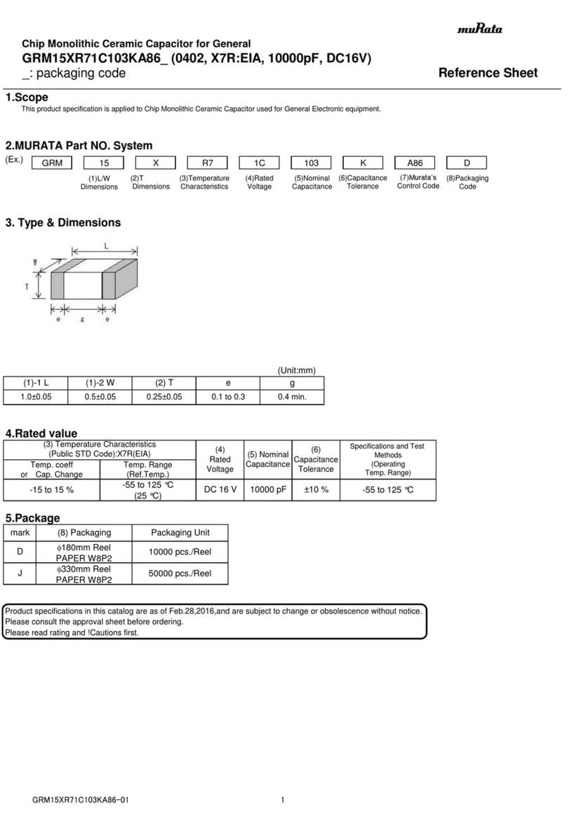
Murata GRM15XR71C103KA86 Series Reference sheet
