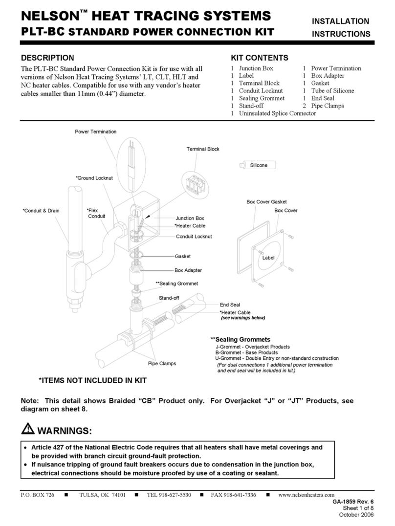
Bender ATICS-2 Series User manual

Kurzanleitung/Quickstart DE/ENATICS-2-ISO_D00046_04_Q_DEEN / 02.2021
ATICS-2...-ISO
Automatische Umschaltgeräte mit Überwachung für ungeerdete Sicher-
heitsstromversorgungen - Software-Version: D333 V1.3x, D334 V1.3x,
D335 V1.0x, D308 V1.2x
Automatic transfer switching devices with monitoring functions for
unearthed safety power supplies - Software version: D333 V1.3x, D334
V1.3x, D335 V1.0x, D308 V1.2x

2 ATICS-2-ISO_D00046_04_Q_DEEN / 02.2021
ATICS-2...-ISO
Dokumentation
Diese Kurzanleitung ersetzt nicht das Handbuch.
i
Bestandteil der Gerätedokumentation sind
diese Kurzanleitung, die „Sicherheits-
hinweise für Bender-Produkte“, das dazuge-
hörige Handbuch bzw. die Checkliste und die
Dokumentation zu ATICS-ES bei -ES-
Variante, herunterladbar unter https://www.
bender.de/service-support/downloadbe-
reich. Es muss sichergestellt sein, dass das
Personal die Handbücher gelesen und alle
Hinweise die die Sicherheit betreffen verstan-
den hat.
Lieferumfang und Beschreibung
• ATICS® Umschalt- und Überwachungsgerät
einschließlich Steckverbinder, Brücke und
Abdeckungen
• Messstromwandler STW2 und STW3
• Kurzanleitung und Checkliste
• Sicherheits-hinweise für Bender-Produkte
Weitere benötigte Systemkomponenten
• IT-System-Transformator mit Temperatur-
überwachung
• Melde- und Prüfkombination MK… oder/
und Melde- und Bedientableaus TM…oder/
und CP9xx
• Bypassschalter (empfohlen)
• Isolationsfehlersuchgerät EDS151 (empfoh-
len)
• Nur bei Schraubmontage:
Befestigungsschrauben M5
• Für die Variante „ATICS® für 400-Volt-Systeme
ohne N-Leiter“ dürfen nur die von Bender
empfohlenen Transformatoren (T5, T6) ver-
wendet werden (siehe Handbuch).
Bestimmungsgemäße Verwendung
Die Umschaltgeräte der Baureihe ATICS® enthalten
alle Funktionen zur Umschaltung zwischen zwei
unabhängigen Zuleitungen sowie zur Über-
wachung von ungeerdeten Stromversorgungen.
Eine andere oder darüber hinausgehende
Benutzung gilt als nicht bestimmungsgemäß.
Documentation
This quick start does not replace the manual.
i
Part of the device documentation are this
quickstart, the enclosed “Safety instructions
for Bender products“, the manual or the che-
cklist and the documentation for ATICS-ES at
-ES variant, downloadable at https://www.
bender.de/en/service-support/downloads. It
must be ensured that the personnel has read
the manuals and understood all safety inst-
ructions.
Scope of delivery and describtion
• ATICS® transfer switching device including
connectors, bridge and terminal covers
• Current transformers STW2 and STW3
• Quickstart and checklist
• Safety instructions for Bender products
Other system components required
• IT system transformer with temperature mo-
nitoring
• Alarm indicator and test combination MK…
or/ and alarm indicator and operator panel
TM…or/ and CP9xx
• Bypass switch (recommended)
• Insulation fault locator EDS151 (recommen-
ded)
• For screw mounting only:
mounting screws M5
• Only the transformers recommended by
Bender (T5, T6) may be used for the „ATICS®
for 400-volt systems without N conductor“
variant (see manual).
Indended use
The ATICS® transfer switching devices provide all
functions for changeover between two indepen-
dent power supplies and for monitoring uneart-
hed power supplies.
Any use other than that described in this
manual is regarded as improper.

ATICS-2...-ISO
ATICS-2-ISO_D00046_04_Q_DEEN / 02.2021 3
Einsatzgebiete:
• Medizinisch genutzte Bereiche der Gruppen
1 und 2 nach DIN VDE 0100-710 und IEC
60364-7-710.
• Gebäudehauptverteiler Krankenhaus (DIN
VDE 0100-710)
• Versammlungsstätten (DIN VDE 0100-718)
• Notstromversorgungen
• Heizung, Klima, Lüftung, Kühlung
• EDV, Rechenzentren
• Feuerlösch- und Sprinkleranlagen
Gerätespezifische Sicherheitshinweise
I Lebensgefahr! Anlagenteile und
Steckerverbinder stehen unter Spannung!
Bei Montage und Anschluss: Anlagenteile
nicht berühren. Anlage spannungsfrei schal-
ten. ATICS® in Handbetrieb schalten und in
Schaltposition „0“ stellen. Umschalt- und
Überwachungsgerät verriegeln und mit
Schloss gegen unbeabsichtigtes Einschalten
sichern.
I Vorsicht: Fehlerhafte Isolationsmessung
möglich. In einem IT-System darf nur ein
Isolationsüberwachungsgerät vorhanden
sein, sonst kommt es zu Fehlmessungen.
ATICS® beinhaltet ein Isolationsüber-
wachungsgerät.
I Vorsicht beim Betrieb von ATICS in der
Version „-ES“ ohne den externen
Energiespeicher ATICS-ES! Der beiliegende
Blindstecker muss auf den Energiespeicher-
Anschluss des ATICS gesteckt werden, sobald
kein ATICS-ES angeschlossen ist. Dieser
Blindstecker (A370261) dient dem
Berührschutz vor gefährlichen Spannungen.
I Warnung: Zerstörungsgefahr durch fal-
sche Netzspannung! Zugelassene
Netzspannung dem Typenschild entneh-
men.
Areas of application:
• Group 1 and 2 medical locations according
to DIN VDE 0100-710 and IEC 60364-7-710
• Hospital main distribution boards (DIN VDE
0100-710)
• Locations open to the public (DIN VDE 0100-
718)
• Emergency power supplies
• Heating, air conditioning, ventilation, cooling
• EDP, computer centres
• Fire extinguisher and sprinkler systems
Device-specific safety instructions
I Danger! Parts of the system and connec-
tors are live. During installation and con-
nection: Do not touch parts of the system.
Make sure that the power supply has been
disconnected and the system is dead. Switch
the ATICS® to manual mode and to switch
position „0“. Lock the changeover device
with a padlock to prevent it starting accid-
ently.
I caution: Avoiding incorrect insulation
measurements. Only one insulation monito-
ring device may exist in an IT system to pre-
vent erroneous measurements. ATICS® inclu-
des an insulation monitoring device.
I caution when operating ATICS in version
„-ES“ without the external energy storage
ATICS-ES! The enclosed dummy plug must
be plugged into the energy storage connec-
tion of the ATICS as soon as no ATICS-ES is
connected. This dummy plug (A370261) pro-
tects against dangerous voltages when tou-
ched.
I Warning: Risk of damage due to false
mains voltage! The permissible mains volta-
ge is indicated on the nameplate.

4 ATICS-2-ISO_D00046_04_Q_DEEN / 02.2021
ATICS-2...-ISO
Geräteübersicht
1. Grüne Steckvorrichtung für Leitung 1 und
Leitung 2
2. Bedientasten
3. Sichtfenster für Schaltposition
4. Anschluss für Energiespeicher ATICS-ES (nur in
„-ES“ Version) / Anschluss für Versor-
gungsspannungen (nur in „-400“ Version)
5. Handbetrieb des Gerätes, Anzeige
Schaltposition
6. Sechskantschlüssel für Handbetrieb
7. Klarsichtabdeckung für Handbetrieb des
Umschaltgerätes, plombierbar
8. Anschlussplan für Leitungen 1, 2 und 3
9. Drei kodierte Anschlussstecker
10. Abschließvorrichtung für Schaltposition 0
11. Grüne Steckvorrichtung für Leitung 3
12. LCD-Anzeige
13. Betriebs- und Alarm-LEDs
1 5432
8
7
6
11 10 9
12
13
Device overviev
1. Green plug device for Line 1 and Line 2
2. Control buttons
3. Inspection window for switch position
4. Connection for energy storage ATICS-ES (only
in „-ES“ version) / Connection for supply volta-
ges (only in „-400“ version)
5. Manual mode of the device, display of swit-
ching position
6. Allen key for manual mode
7. Transparent cover for changeover switch (ma-
nual mode), sealable
8. Wiring diagram for lines 1, 2 and 3
9. Three coded connector plugs
10. Locking device for switch position 0
11. Green plug device for Line 3
12. LCD
13. Operating and alarm LEDs

ATICS-2...-ISO
ATICS-2-ISO_D00046_04_Q_DEEN / 02.2021 5
Maße
A: Frontalansicht
B: Seitenansicht
C: Rückansicht (Maße für Schraubmontage auf
Montageplatte)
D: Ausschnitt der Verteilerabdeckung anpassen
1): Optional zu montierende Hilfskontakte
Montage
Benötigtes Werkzeug
Zum Anschließen des Leistungsteils und der
Steuerleitungen folgendes Werkzeug verwenden:
• Torx® Schraubendreher T20 oder
6,5 x 1,2 mm
• Schraubendreher 2,5 x 0,4 mm
• Sechskantschlüssel 4 mm
234
11515
220
263
245
18
1)
A
222
47
D
132
132
176
176
C
46
75
52
45
B
Dimensions
A: Front view
B: Side view
C: Rear view (Dimensions for screw mounting on
mounting plate)
D: Adapt the cut-out of the terminal cover
1): Optional auxiliary contacts to be mounted
Mounting
Tools required
Use the following tool to connect the power secti-
on and the control cables:
• Torx® screwdriver T20 or 6.5 x 1.2 mm
• Screwdriver 2.5 x 0.4 mm
• Allen key 4 mm

6 ATICS-2-ISO_D00046_04_Q_DEEN / 02.2021
ATICS-2...-ISO
Klemmenabdeckung demontieren
Sperrhaken (B) in der Mitte der oberen und unte-
ren Klemmenabdeckung (A) mit einem
Schraubendreher zurückdrücken.
Klemmenabdeckung abheben.
Montage auf Hutschiene
i
Schrauben müssen festgezogen werden,
sonst kann ATICS® durch die beim Schalten
entstehenden Vibrationen beschädigt wer-
den.
1. ATICS® auf den oberen Rand der Hutschiene
aufsetzen.
2. Den unteren gelben Verriegelungsschieber (C)
mit einem Schraubendreher nach unten zie-
hen und ATICS® durch leichten Druck einrasten
lassen. Durch leichtes Ziehen am unteren Teil
des Gehäuses prüfen, ob Verriegelungs-
schieber richtig eingerastet ist.
3. Alle Klemmen mit Innensechskantschrauben
festschrauben. Anzugsmoment: 5 Nm.
4. Klemmenabdeckungen befestigen.
5. Schrauben (D) festdrehen (PZ1, 8,8 lb-in,
1 Nm).
A
B
N
N
N
N
N
C
N
Removing the terminal covers
Push back the locking hook (B) in the middle of
the top and bottom terminal cover (A) by using a
screwdriver.
Remove the terminal cover.
Mounting on DIN rail
i
Screws must be tightened, otherwise ATICS®
can be damaged by the vibrations of the
switch-over.
1. Place the ATICS® on the top edge of the rail.
2. Use a screwdriver to pull down the lower yel-
low slide lock (C) and snap the ATICS® into pla-
ce with slight pressure. Check that the slide
lock is properly snapped into position by pul-
ling slightly the lower part of the enclosure.
3. Secure all terminals with Allen screws.
Tightening torque: 5 Nm.
4. Fasten the terminal covers.
5. Tighten the mounting screws (D) (PZ1,
8.8 lb-in, 1 Nm).
D

ATICS-2...-ISO
ATICS-2-ISO_D00046_04_Q_DEEN / 02.2021 7
ATICS® auf Montageplatte montieren
i
• Maßbild Rückansicht beachten.
• Befestigungsschrauben M5 nutzen.
I Vorsicht: Schraubenköpfe oder
Unterlegscheiben verringern
Spannungsabstände. Befestigungs-
schrauben dürfen nicht zu dicke Schrauben-
köpfe oder Unterlegscheiben haben, damit
Spannungsabstände zu aktiven Leitern groß
genug sind.
Bei Montage auf leitendem Material: Platte
erden und unter den Bereich der Anschlüsse
Isolierstoff unterlegen.
1. Innensechskantschrauben der Klemmen (C)
lösen.
2. Grüne Steckvorrichtungen (D) oben und unten
entfernen.
3. Schwarze Brücke unten (E) entfernen.
4. ATICS® mit Befestigungsschrauben M5 (22 lb-
in, 2,5 Nm) auf Montageplatte befestigen (sie-
he Maßbild).
5. Schwarze Brücke unten (E) einstecken.
6. Grüne Steckvorrichtungen (D) oben und unten
einstecken.
7. Alle Klemmen (C) mit Innensechskant-
schrauben festschrauben.
Anzugsmoment: 5 Nm.
8. Klemmenabdeckungen befestigen.
!
C
D
E
N
Mounting the ATICS® on mounting plate
i
• Observe dimension drawing rear view.
• Use fixing screws M5.
I caution: Screw heads or washers reduce
voltage clearance. Provide for sufficient
learance to live conductors (voltage clea-
rance) by using mounting screws with flat
screw heads and flat washers.
If mounted on electrically conductive mate-
rial: the mounting plate has to be earthed
and the area under the terminals has to be
covered with insulating material.
1. Undo the Allen screws of the terminals (C).
2. Remove the green connectors (D) top and bot-
tom
3. Remove the black bridge (E) bottom
4. Fasten the ATICS® to the mounting plate with
M5 (22 lb-in, 2.5 Nm) mounting screws (see di-
mension diagram).
5. Insert the black bridge (E), bottom
6. Plug in the green plug connectors (D) top and
bottom
7. Tighten the Allen screws on the terminals (C).
All terminals, including the unused terminals
must be fully tightened. Tightening torque:
5 Nm.
8. Fasten the terminal covers.

8 ATICS-2-ISO_D00046_04_Q_DEEN / 02.2021
ATICS-2...-ISO
Anschluss
Anschlüsse anklemmen, einstecken
und sichern
Anschlüsse gemäß Anschlussplan mit den
Steckvorrichtungen (A, B) und den drei Anschluss-
steckern (C) verbinden.
• Für den Anschluss der Leitungen 1, 2, 3 an
die Steckvorrichtungen (A, B) die
Abisolierlänge 20 mm beachten und keine
Aderendhülsen verwenden. Torx®-Schrau-
bendreher T20 oder Schlitzschraubendreher
6,5 x 1,2 mm verwenden. Anzugsmoment:
2,5 Nm (≤ 25 mm²) bzw. 4,5 Nm (> 25 mm²).
Auf kurzschluss- und erdschlusssichere
Verlegung der Leitungen achten!
• Für den Anschluss der drei Anschlussstecker
(C) Schlitzschraubendreher 2,5 x 0,4 mm ver-
wenden. Abisolierlänge: 7 mm.
Anzugsmoment: 0,22…0,25 Nm.
1. Untere grüne Steckvorrichtung (B) einstecken
und mit Befestigungsschrauben sichern.
Danach obere grüne Steckvorrichtung (A) ein-
stecken und mit Befestigungsschrauben si-
chern.
2. Drei Anschlussstecker (C) einstecken.
i
Nur ATICS…400: Anschlussstecker oben ein-
stecken. (Gegenüberliegende Seite von C).
i
Nur ATICS in der Version „-ES“: Anschluss
zum Energiespeicher ATICS-ES durch mitge-
liefertes Kabel herstellen.
C
A
B
N
N
Connection
Fastening, inserting and
securing connections
Connect the terminals according to the wiring
diagram to the plug connectors (A, B) and the
three connector plugs (C).
• Connect the lines 1, 2 and 3 to the plug con-
nectors (A, B) with a Torx® screwdriver T20 or
a slotted screwdriver 6.5 x 1.2 mm. Consider
a stripping length of 20 mm and do not use
ferrules. Tightening torque: 2.5 Nm (≤ 25
mm²) or 4.5 Nm (> 25 mm²). The connecting
wires must be laid so that they are short-cir-
cuit and earth-fault proof!
• Connect the connector plugs (C) with a slot-
ted screwdriver of 2.5 x 0.4 mm. Stripping
length: 7 mm.
Tightening torque: 0.22…0.25 Nm.
1. Insert bottom green plug connector (B) and
secure with mounting screws. After that, insert
top green plug connector (A) and secure with
mounting screws.
2. Insert the other three connector plugs (C).
i
ATICS…400 only: Connect connector plug
on the top of the housing (opposite side of
(C).
i
Only ATICS in the „-ES“ version: Connection
to the ATICS-ES energy storage device with
the supplied cable.

ATICS-2...-ISO
ATICS-2-ISO_D00046_04_Q_DEEN / 02.2021 9
Anschlussbeispiel
i
Weitere Anschlussbeispiele siehe Handbuch.
Klemme Bedeutung
1, 3 Anschluss Leitung 1 (Eingangsleitung) L, N
5, 7 Anschluss Leitung 2 (Eingangsleitung) L, N
4, 6 Anschluss Leitung 3 (Ausgangsleitung) N, L
l, k (grau) Anschluss Messstromwandler T3 (STW3) zum
Überwachen des Laststroms hinter der Umschalt-
einrichtung (Kurzschlussüberwachung)
GND, En/Ex
(grau)
Anschluss darf nur an Variante ATICS-2-ISO-xx-ES
ausschließlich für ATICS-ES verwendet werden.
IN1/GND, IN1
(grau)
Digitaler Eingang, parametrierbar, z. B. zum
Überwachen der Schaltposition des Umschalt- und
Überwachungsgerätes
NC (grau) nicht benutzt
*An diese Klemmen ausschließlich ATICS-ES
an Variante ATICS-2-ISO-xx-ES anschließen!
*Solely connect ATICS-ES to variant
ATICS-2-ISO-xx-ES with these terminals!
Connection example
i
Further Connection examples see manual.
Terminal Meaning
1, 3 Connection for Line 1 (input line) L, N
5, 7 Connection for Line 2 (input line) L, N
4, 6 Connection for Line 3 (output line) N, L
l, k (grey) Connection measuring current transformerT3
(STW3) for monitoring the load current downs-
tream the transfer switching device (short-circuit
monitoring)
GND, En/Ex
(grey)
Connection must only be used on variant ATICS-2-
ISO-xx-ES solely for ATICS-ES.
IN1/GND, IN1
(grey)
Digital input, congurable, for example, for
monitoring the switch position of the transfer
switching device
NC (grey) not used

10 ATICS-2-ISO_D00046_04_Q_DEEN / 02.2021
ATICS-2...-ISO
L1/IT, L2/IT
(grün)
Ankopplung an das IT-System. Überwachung des
Isolationswiderstandes. Bei bestehendem Iso-
lationsfehler: Einspeisung eines Prüfstromsignals
zur Isolationsfehlersuche. Zweipolig absichern über
Schmelzsicherung 6 A.
E, KE (grün) Anschluss von E und KE mit zwei getrennten Leitun-
gen an PE. Vorsicht: Die mit GND bezeichneten
Klemmen dürfen nicht mit PE verbunden werden.
Z1, Z2 (grün) Temperaturüberwachung des IT-System-Trans-
formators
k/IT, l/IT
(grün)
Anschluss Messstromwandler STW2 zum Überwa-
chen des Laststroms hinter dem IT-System-Trans-
formator (Überwachung auf Überlast)
A, B (schwarz) Anschluss BMS-Bus
NC (schwarz) nicht benutzt
14, 12, 11
(schwarz)
Alarmrelais, Funktion parametrierbar
Inbetriebnahme
i
Informationen zu Fehlermeldungen sind im
Handbuch im Kapitel „Störungshilfen“ ver-
merkt.
Handbetrieb aktivieren
Klarsichtabdeckung des Um-
schalt- und Überwachungs-
gerätes öffnen. Meldung
„Handbetrieb“ erscheint.
Automatikbetrieb aktivieren
Klarsichtabdeckung des Umschalt-
und Überwachungsgerätes schlie-
ßen und bei Bedarf verplomben.
L1/IT, L2/IT
(green)
Connection to the IT system. Monitoring the insu-
lation resistance. When there are insulation faults:
Locating current fed in for insulation fault location.
Bipolar protection via 6 A back-up fuse.
E, KE (green) Connection of E and KE to two separate PE lines.
Caution: The terminals labelled GND must not be
connected to PE.
Z1, Z2 (green) Temperature monitoring for the IT system trans-
former
k/IT, l/IT
(green)
Connection for measuring current transformer
STW2 to monitor the load current downstream of
the IT system transformer (overload monitoring)
A, B (black) BMS bus connection
NC (black) not used
14, 12, 11
(black)
Alarm relay, programmable function
Commissioning
i
Information on errorcodes can be found in
the „Troubleshooting“ section of the manual.
Enabling manual mode
Open the transparent cover the
automatic transfer switching de-
vice The display shows „Manual
mode“.
Enabling automatic mode
Close the transparent cover of the
automatic transfer switching de-
vice and seal it, if necessary.

ATICS-2...-ISO
ATICS-2-ISO_D00046_04_Q_DEEN / 02.2021 11
MK... bzw. TM... bzw. CP9xx parametrieren
I Vorsicht: Fehlende oder falsche Anzeigen
an MK…, TM…, CP9xx oder COM465IP
wegen veralteter Software. Ältere
Betriebssoftware von MK…, TM…, FTC…
oder COM465IP aktualisieren oder austau-
schen. Konfigurationssoftware TMK-SET ak-
tualisieren.
i
Parametrieren Sie bei MK… bzw. TM…bzw.
CP9xx zusätzlich zur Meldung einen kurzen
Hinweis, was zu tun ist oder wer zu benach-
richtigen ist.
MK… bzw. TM… bzw. CP9xx müssen mindestens
die folgenden vom ATICS® erkannten Fehler an-
zeigen:
• Ausfall Leitung 1, Ausfall Leitung 2
• Gerätestörung, -ausfall ATICS®
• Ausfall der anderen MK… bzw. TM… bzw.
CP9xx
• Isolationsfehler, Überlast, Übertemperatur
• Optional: EDS-Kanäle mit Stromkreis- und/
oder Raumbezeichnung
• Gerätefehler mit vollständigem Text bzw.
Errorcode
Mindesteinstellungen vornehmen
Folgende Mindesteinstellungen müssen gegeben
sein:
• BMS-Bus-Adresse (siehe „Einstellmenü 9:
Schnittstelle“ im Handbuch)
• Laststrom gemäß angeschlossenem IT-
System-Transformator (siehe „Einstellmenü 4:
IT-System“ im Handbuch)
• Verzögerungszeiten (siehe Kapitel „Einstellen
und Prüfen nach Checkliste“ im Handbuch)
i
Am ATICS® ist ab Werk kein Passwort einge-
stellt. Für den Betrieb unbedingt ein Passwort
einstellenund aktivieren (siehe„Einstellmenü
11: Passwort“ im Handbuch).
Configure MK… resp. TM… resp. CP9xx
I caution: Missing or false messages on the
MK…, TM…, CP9xx or COM460IP because
of out-dated software. Replace or update
older operating software of MK…, TM…,
FTC… or COM465IP. Update TMK-SET confi-
guration software.
i
In addition to the message, configure at
MK... resp. TM... resp. CP9xx a short remark of
what needs to be done and who is to be in-
formed.
MK… resp. TM… resp. CP9xx must display at least
the following faults detected by the ATICS®:
• Failure Line 1, failure Line 2
• Device error, device failure ATICS®
• Failure of the other MK… or TM… or CP9xx
• Insulation fault, overload, overtemperature
• Optional: EDS channels with circuit and/or
room designation
• Device error with complete text or error code
Minimum parameters settings
The following minimum default settings have to
be carried out:
• BMS bus address (see „Settings menu 9:
Interface“ in the operating manual)
• Load current according to the connected IT-
System transformer (see „Settings menu 4: IT
System“ in the operating manual)
• Delay times (see chapter „Setting and testing
according to the checklist“ in the operating
manual)
i
By default, there is no password set on the
ATICS®. For operation of the device, it is abso-
lutely essential to enter and enable a pass-
word (see „Settings menu 11: password“ in
the operating manual).

12 ATICS-2-ISO_D00046_04_Q_DEEN / 02.2021
ATICS-2...-ISO
Bedien- und Anzeigenelemente
LED/Taste Bedeutung
LED„1“ leuchtet: Leitung 1 ist bereit
LED„2“ leuchtet: Leitung 2 ist bereit
LED„ALARM“ leuchtet: Alarmmeldung vorhanden
LED„COM“ blinkt: Kommunikation über den BMS-Bus
„INFO“
„ESC“
Abfrage von Standardinformationen
Menüfunktion ohne Parameteränderung verlassen
„TEST“ Testmenü aufrufen,
Parameter ändern, scrollen
„RESET“ Alarm- und Fehlermeldungen zurücksetzen,
Rückschaltsperre aufheben,
Parameter ändern, scrollen
„MENU“ Umschalten zwischen Standardanzeige, Alarm-
anzeige und MENU,
Bestätigung Parameteränderung
ALARM
12 COM
Operating and display elements
LED/Button Meaning
LED ”1“ lights up: Line 1 is ready
LED ”2“ lights up: Line 2 is ready
LED ”ALARM“ lights up: alarm message exists
LED ”COM“ ashes during communication via the BMS bus
”INFO“
”ESC“
Calls up standard information
Exit menu function without changing parameters
”TEST“ Calls up test menu
Parameter changes, scrolling
”RESET“ Resets alarm and fault messages, unlocks switching
back interlocking function
Parameter changes, scrolling
”MENU“ Toggles between the standard display, alarm
display and the„MENU“
Conrms parameter changes

ATICS-2...-ISO
ATICS-2-ISO_D00046_04_Q_DEEN / 02.2021 13
Anzeigen im Betrieb
Standardanzeige
Pos. Bedeutung Pos. Meaning
1 Leitung 1: Messwerte Netz-
spannung und Frequenz
1 Line 1: Measured values of mains
voltage and frequency
2 Schaltposition des Umschalt-
und Überwachungsgerätes
2 Switch position of the automatic
transfer switching device
3 Leitung 2: Messwerte Netz-
spannung und Frequenz
3 Line 2: Measured values of mains
voltage and frequency
4 Anzeige der Last im IT-System
in %. Der maximale Laststrom
ist einstellbar.
Alarmstatus / Alarm status:
kein Alarm / no alarm Alarm
Datum, Alarmmeldungen, Rückschaltsperre,
Handbetrieb, Bypassbetrieb, Countdown-Zähler für
Rückschaltzeit /
Date, alarm messages, switching back interlocking
function, manual mode, bypass mode, countdown
timer for return transfer time
4 Display of the load in the IT system
in %.The maximum load current
is adjustable
5 alternative Anzeigen15 Alternate Displays1
6 Datum 6 Date
7 Messwert Isolationswiderstand 7 Measured value of insulation
resistance
228 V
50 . 0Hz
231 V
50 . 0Hz
160kΩ 12 : 23
07.08.2017
35%
120
213
456
7
Displays in operation
Standard Display

14 ATICS-2-ISO_D00046_04_Q_DEEN / 02.2021
ATICS-2...-ISO
Menü
Taste „MENU“ drücken um das Hauptmenü zu öffnen.
• oder drücken um eine Menüebene nach oben bzw. nach unten wechseln.
• drücken, um den angewählten Menüpunkt zu bestätigen.
• „ESC“ drücken, um das Menü zu verlassen.
Menü Übersicht
Hauptmenü Bedeutung Untermenü Bedeutung / Einstellung
Zurück Menümodus verlassen
1. Alarm/Messw. Zeigt aktuelle Statusmeldungen, Alarmmeldungen und Messwerte an
2.Umschaltung Zeigt Informationen zur Umschaltung an (Anzahl,Test)
3. Historie/Logger Anzeige der Logge-
rinhalte
1. Historie Eigene Alarmmeldungen und ausgeführte Tests:Wert und Zeit
2. Datenlogger Historie zu Messwerten an: Leitung 1, Leitung 2, Position, Laststrom im
TN-System I(3), Isolation,Trafolast
3. Kong. Logger Historie zum Menü„Einstellungen“:Wert und Zeit
4.Testlogger Historie zu ausgeführten Tests der Umschaltung
5. Servicelogger Historie zu ausgeführten Servicemaßnahmen
4. Einstellungen Diverse Einstellungen
für das Gerät
1. Umschalten Zeiteinstellungen, System, Rückschaltsperre, bevorzugte Leitung,
Generator,Test- und Serviceintervall
2. Spannung Zeiteinstellungen, Spannungsbereiche, Hysterese
3. Strom Kurzschlusserkennung
4. IT-System Ansprechwerte Isolation,Trafolast,Temperatur, Fehlersuche
5. Relais Funktion und Arbeitsweise
6. Digitaler Eingang Funktion, Arbeitsweise, Verzögerung
7. Datenlogger Ändern, Überschreiben, Löschen
8. Sprache deutsch, englisch, französisch, polnisch
9. Schnittstelle Einstellung der BMS-Bus-Adresse dieses Gerätes.
Änderung von Einstellungen über Schnittstelle zulassen,
Ausführung einesTests über Schnittstelle zulassen.
10. Uhr Format, Einstellung Uhrzeit, Datum
11. Passwort Passwort für Einstellungen undTest aktivieren bzw. einstellen
12. Service Einstellungen nur durch autorisiertes Bender-Servicepersonal bestimmt.
5. Steuerung TEST und RESET für
das Gerät ausführen
1.TEST Isometer, Umschaltung, letzte Umschaltung alsTest, Generator
2. RESET Alarm beenden, Rückschaltsperre aufheben, Alarmwert ändern für
die maximal zulässige Anzahl durchgeführter Umschaltungen und der
maximal zulässigen Anzahl der Betriebsstunden
6. Digitaler Eingang Spannungspegel des digitalen Eingangs anzeigen
7. Info Informationen zum Gerätetyp und der Firmware-Versionen anzeigen

ATICS-2...-ISO
ATICS-2-ISO_D00046_04_Q_DEEN / 02.2021 15
Menu
Press the „MENU“ button to open the main menu.
• Press or to go up resp. down one menu level.
• Press to confirm the selected menu item.
• Press „ESC“ to leave the menu.
Menu overview
Main menu Meaning Submenu Meaning/ Setting
Exit Exit menu mode
1. Alarm/ meas. val. Displays current status messages, alarm messages and measured values
2. Changeover Displays information on the changeover function (number, test)
3. History/Logger Displays logger
information
1. History Alarm messages and tests which have been performed: value and time
2. Data logger History of measured values: Line 1, Line 2, position, load current in theTN
system I(3), insulation, transformer load
3. Cong. Logger History of the„Settings“ menu: value and time
4.Test logger History of the tests of the changeover switch carried out
5. Service logger History of the service activities carried out
4. Settings Various settings for
the device
1. Changeover Setting the date and time, system, switching back interlocking function,
preferred supply, generator, test and service interval
2.Voltage Delay times, voltage ranges, hysteresis
3. Current Short-circuit detection
4. IT system Response values insulation, transformer load, temperature, fault location
5. Relay Mode of operation and relay mode
6. Digital input Mode of operation, function, delay
7. Data logger Modify, overwrite, delete
8. Language Deutsch, English, Francais, Polski
9. Interface Setting the BMS bus address of this device. Allow the settings to be
changed via the interface. Allow a test to be run via interface.
10. Clock Set date format and date and time
11. Password Enable resp. set password for settings and test
12. Service Only for settings to be made by authorised Bender Service personnel
5. Control RunTEST and RESET
for the device
1.TEST Isometer, changeover, last changeover saved as a test, generator
2.RESET Reset alarm messages, cancel the switching back interlocking function,
change the alarm value for the max. permissible number of changeover
operations performed and the max. permissible number of operating
hours
6. Digital input Display voltage level of the digital input
7. Info Display information on device type and rmware versions

16 ATICS-2-ISO_D00046_04_Q_DEEN / 02.2021
ATICS-2...-ISO
I Warnun g! Bei Funktionsprüfung
(Wiederholungsprüfung) ohne Bypass-
Schalter kommt es zu einer kurzen
Unterbrechung der Spannungsversorgung.
Vor Funktionstest unbedingt Rücksprache
mit dem medizinischen Personal halten!
i
Hinweis zu wiederkehrender Prüfung
„Testmenü 2: Umschaltung auto“ (siehe
auch Checkliste).
Umschaltung auto.:
Test der Umschaltung. Das Gerät schaltet auf die
redundante Leitung um. Die Umschaltzeit t(1->2)
wird angezeigt. Nach Ablauf der eingestellten Zeit
t(Test) schaltet das Gerät auf die bevorzugte
Leitung zurück.
Abbrechen:
Zurück zum Testmenü
Das Datum des Tests wird im Testlogger gespei-
chert, um nach Ablauf des Testintervalls an den
nächsten Test zu erinnern. Die Meldungen dieses
Tests werden auch in den Historienspeicher ge-
speichert.
Umschaltung auto.
Abbrechen
Umschaltung auto.
Test
t (1->2): 457ms
t (Test): 10s
Beenden: RESET
I Warning! During a function test (recurrent
test) without bypass switch there is a short
interruption of the current supply. Consult
the medical personnel before performing a
function test!
i
Note on periodic verification „Test menu 2:
autom. changeover“ (see also checklist)
:
Autom. changeover:
Test of the changeover function. The device chan-
ges to the redundant line. The changeover period
t(1->2) is displayed. After the set time t(test) has
elapsed, the device changes back to the preferred
line.
Cancel:
Back to test menu
The date of the test is saved in the test data logger
to remember the next test once the test interval
has elapsed. The messages from this test are also
stored in the history memory.
Autom. changeover
Cancel
Autom. changeover
Test
t (1->2): 457ms
t (Test): 10s
Quit: RESET

ATICS-2...-ISO
ATICS-2-ISO_D00046_04_Q_DEEN / 02.2021 17
Bestellangaben
Typ Nennspg. UnBemessungsbetriebsstrom IeArt.-Nr. Handbuch Nr.
ATICS-2-63A-ISO AC 240V AC 63 A B92057202 D00046
ATICS-2-63A-ISO-ES* AC 240V AC 63 A B92057206 D00046
ATICS-2-63A-ISO-400 AC 415V AC 63 A B92057204 D00046
ATICS-2-80A-ISO AC 240V AC 80 A B92057203 D00046
ATICS-2-80A-ISO-ES* AC 240V AC 80 A B92057207 D00046
ATICS-2-80A-ISO-400 AC 415V AC 80 A B92057205 D00046
STW2 Messstromwandler (Laststromüberwachung IT-System),
Ie: AC 50 A B942709
STW3 Messstromwandler (Kurzschlussüberwachung) für ATICS® < 100 A;
Ie: AC 100 A B98021000
SWL-100A Messstromwandler (Laststromüberwachung IT-System,
Ie: AC 100 A B98021002
ATICS-BP-2-63A-SET
Inhalt Bypass-Schalter-Set (Ie: AC 63 A):
• Bypass-Schalter 63 A einzeln, 2-polig, Schaltfolge: I-I+II-II, mit Hilfs
kontakt, Brücke, Klemmenabdeckung
• Hilfskontakt für ATICS®
• Leuchtmelder grün/rot für Hutschienenmontage
B92057252 D00162
ATICS-BP-2-80A-SET
Inhalt Bypass-Schalter-Set (Ie: AC 80 A):
• Bypass-Schalter 80 A einzeln, 2-polig, Schaltfolge: I-I+II-II, mit Hilfs
kontakt, Brücke, Klemmenabdeckung
• Hilfskontakt für ATICS®
• Leuchtmelder grün/rot für Hutschienenmontage
B92057253 D00162
EDS151 Isolationsfehlersuchgerät B91080101 D00107
ESS3680
Transformator 3,68 kVA, AC 400V / 230V
Für„ATICS® für 400-Volt-Systeme ohne N-Leiter“ dürfen nur die von
Bender empfohlenenTransformatoren (T5,T6) verwendet werden!
B924744
ATICS-ES Energiespeicher für ATICS-2-63A-ISO-ES und ATICS-2-80A-ISO-ES B72057255 D00009
AN412 Netzgerät DC 12V für Energiespeicher ATICS-ES B924150
* mit Anschlussmöglichkeit für Energiespeicher ATICS-ES

18 ATICS-2-ISO_D00046_04_Q_DEEN / 02.2021
ATICS-2...-ISO
Ordering Information
Type Nominal voltage UnRated operational current IeArt.-No. Manual No.
ATICS-2-63A-ISO AC 240V AC 63 A B92057202 D00046
ATICS-2-63A-ISO-ES* AC 240V AC 63 A B92057206 D00046
ATICS-2-63A-ISO-400 AC 415V AC 63 A B92057204 D00046
ATICS-2-80A-ISO AC 240V AC 80 A B92057203 D00046
ATICS-2-80A-ISO-ES* AC 240V AC 80 A B92057207 D00046
ATICS-2-80A-ISO-400 AC 415V AC 80 A B92057205 D00046
STW2 Measuring current transformer (load current monitoring IT system),
Ie: AC 50 A B942709
STW3 Measuring current transformer (short-circuit monitoring) for ATICS®
< 100 A; Ie: AC 100 A B98021000
SWL-100A Measuring current transformer (load current monitoring IT system),
Ie: AC 100 A B98021002
ATICS-BP-2-63A-SET
Bypass switch set comprising: (Ie: AC 63 A):
• Bypass switch 63 A single, two-pole, sequence of operation: I-I+II-II,
with auxiliary contact, bridge, terminal cover
• Auxiliary contact for ATICS®
• LEDs green/red for DIN rail mounting
B92057252 D00162
ATICS-BP-2-80A-SET
Bypass switch set comprising: (Ie: AC 80 A):
• Bypass switch 80 A single, two-pole, sequence of operation: I-I+II-II,
with auxiliary contact, bridge, terminal cover
• Auxiliary contact for ATICS®
• LEDs green/red for DIN rail mounting e
B92057253 D00162
EDS151 Insulation fault locator B91080101 D00107
ESS3680
Transformer 3.68 kVA, AC 400V / 230V
For„ATICS® for 400 Volt systems without N-conductor“ only trans-
formers recommended by Bender (T5, T6) may be used!
B924744
ATICS-ES Energy storage for ATICS-2-63A-ISO-ES and ATICS-2-80A-ISO-ES B72057255 D00009
AN412 Power supply DC 12 V for Energy storage ATICS-ES B924150
* with connectivity for Energy storage ATICS-ES

ATICS-2...-ISO
ATICS-2-ISO_D00046_04_Q_DEEN / 02.2021 19

Alle Rechte vorbehalten.
Nachdruck und Vervielfältigung
nur mit Genehmigung des Herausgebers.
Bender GmbH & Co. KG
Postfach 1161 • 35301 Grünberg • Deutschland
Londorfer Str. 65 • 35305 Grünberg • Deutschland
Tel.: +49 6401 807-0 • Fax: +49 6401 807-259
All rights reserved.
Reprinting and duplicating
only with permission of the publisher.
Bender GmbH & Co. KG
PO Box 1161 • 35301 Grünberg • Germany
Londorfer Str. 65 • 35305 Grünberg • Germany
Tel.: +49 6401 807-0 • Fax: +49 6401 807-259
ATICS-2-ISO_D00046_04_Q_DEEN / 02.2021/ pdf / © Bender GmbH & Co. KG, Germany – Subject to change! The specied standards take into account the edition valid until 02/2021 unless otherwise indicated.
This manual suits for next models
6
Table of contents
Other Bender Industrial Electrical manuals
Popular Industrial Electrical manuals by other brands
Murata
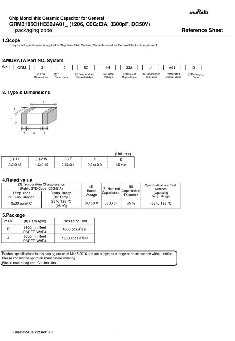
Murata GRM3195C1H332JA01 Series Reference sheet
Murata
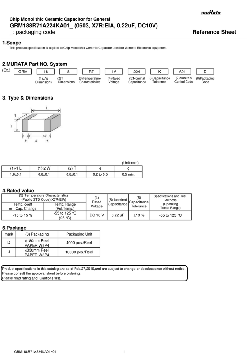
Murata GRM188R71A224KA01 Series Reference sheet
Murata
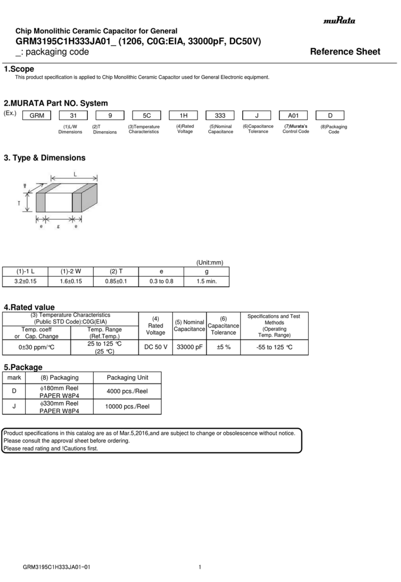
Murata GRM3195C1H333JA01 Series Reference sheet
M-system
M-system 18KYCH instruction manual
Murata
Murata GJM0335C1E6R3CB01 Series Reference sheet
Milltronics
Milltronics ACCUMASS BW500 instruction manual
