Bentel ECL2-UKR User manual

INTRODUZIONE
L’ECLIPSE2èuninseritoreperchiaveelettronicasenzacontattielettrici.L’inseritore
è predisposto per essere fissato a incasso nelle scatole usate per gli interruttori e
le prese domestiche.
CARATTERISTICHE TECNICHE
Compatibilità: Centrali serie Absoluta, Kyo, Norma8/4, NORMA
Assorbimento: 30mA
Banda di frequenza: 125 kHz
Intensità campo magnetico: 65,8dBA/m
Dimensioni (LxAxP): 19 x 35 x 44 mm
Caratteristiche Ambientali: Solo per applicazioni interne (esterne in un con-
tenitore stagno)
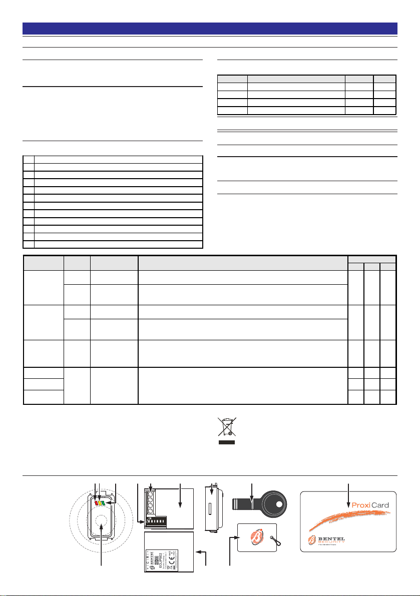
IDENTIFICAZIONE DELLE PARTI
I numeri in grassetto riportati tra parentesi quadre [ ] indicati nei successivi paragrafi
fanno riferimento alle parti riportate in Fig. 1 e descritte nella tabella seguente:
1Spia rossa - Inserimento Aree abilitate sull'inseritore.
2Spia gialla - Inserimento di tipo A.
3Spia verde - Inserimento di tipo B.
4Centro dell'area sensibile.
5Dip-switch per la programmazione dell'Inseritore.
6Morsettiera per i collegamenti.
7ECL2-UKR - Modulo Inseritore Universale: lato morsettiera.
8Cover per il Modulo Inseritore Universale ECL2-UKR.
9Tag di prossimità MiniProxi.
10 Attivatore del tipo SAT2.
11 Tessera di prossimità.
12 ECL2-UKR - Modulo Inseritore Universale: lato etichetta.
DESCRIZIONE DEI MORSETTI
In questo paragrafo sono descritti sinteticamente i morsetti per il collegamento del
lettore ECLIPSE2 ai morsetti della centrale (vedere la tabella seguente).
Morsetto DESCRIZIONE v (V) I (A)
+Alimentazione: positivo 11,0 - 13,8 0,03
CComando – –
RRisposta – –
–Alimentazione: negativo 0–
Il Livello BPI dell'inseritore è 12 V e NON può essere modificato.
Per un corretto funzionamento del sistema di inseritori tra due dispositivi
ECLIPSE2 deve esserci una distanza maggiore di 10 centimetri.
MODALITÀ DI FUNZIONAMENTO
L'InseritoreECLIPSE2è compatibilecontuttele centraliBENTELdiultima generazio-
ne:perl'usoconlecentralidellaserieNORMA8/NORMA4,posizionareilmicrointerruttore
n. 6del dip-switch [5] in posizione ON (di fabbrica in posizione OFF).
Posizionare il microinterruttore 6 prima di alimentare l’inseritore ECLIPSE2.
l microinterruttori 1, 2, 3, 4, 5 del dip-switch [5] servono per programmare l’indirizzo
del dispositivo (vedere la tabella 1).
Avvicinando la chiave elettronica all’area sensibile [4] di un inseritore ECLIPSE2 è
possibileDisinserire oInserirel’impianto.
La procedura per le operazioni di Disinserimento e di Inserimento dell’impianto
tramitel’inseritoreECLIPSE2sonodifferentiasecondodeltipodicentraleinstallata.
Per maggiori informazioni consultare la tabella seguente:
Con la presente, Bentel Security dichiara che il tipo di apparecchiatura radio ECLIPSE2 è conforme alla direttiva 2014/53/UE.
Il testo completo della dichiarazione di conformità UE è disponibile al seguente indirizzo Internet: www.bentelsecurity.com/dc.
Il contenuto di questo manuale può essere soggetto a modifiche senza preavviso e non rappresenta un impegno da parte della BENTEL SECURITY srl.
ATTENZIONE - NON collegare l’ECLIPSE2 al bus quando questo è alimentato; se ciò non fosse possibile collegare i morsetti del bus nel seguente ordine: –; +; R, C.
Informazioni sul riciclaggio
BENTELSECURITYconsigliaai clientidismaltirei dispositiviusati(centrali,
rilevatori, sirene, accessori elettronici, ecc.) nel rispetto dell'ambiente. Metodi
potenziali comprendono il riutilizzo di parti o di prodotti interi e il riciclaggio di
prodotti, componenti e/o materiali. Per maggiori informazioni visitare il sito:
http://www.bentelsecurity.com/index.php?o=environmental
Direttiva Rifiuti di apparecchiature elettriche ed elettroniche (RAEE WEEE)
Nell'Unione Europea, questa etichetta indica che questo prodotto
NON deve essere smaltito insieme ai rifiuti domestici. Deve essere
depositato in un impianto adeguato che sia in grado di eseguire
operazioni di recupero e riciclaggio. Per maggiori informazioni
visitare il sito: http://www.bentelsecurity.com/index.php?o=environmental
MADE
IN
ITALY
ISO 9001
9105.BNT1 ISO 9001
IT-52587
ISO 14001
9191.BNT2 ISO 14001
IT-52588
OHSAS 18001
9192.BSEC OHSAS 18001
IT - 60983
Inseritore per chiave elettronica
Electronic Key Reader
Lector para llave electrónica
Lecteur pour clé électronique
ECLIPSE2
II
II
IITALIANO
OPERAZIONE
Microinter-
ruttore 6
CENTRALI PROCEDURA SPIE
Rossa Gialla Verde
Disinserimento
OFF ABSOLUTA,
KYO320, KYOUNIT,
NORMA
1. Avvicinare la Chiave Elettronica all'area sensibile dell'inseritore.
2. Allo spegnimento di tutte le spie allontanare la Chiave Elettronica dall’area sensibile
dell'inseritore. L’impianto verrà così disinserito. Spenta Spenta Spenta
ON NORMA8/
NORMA4
1. Avvicinare la Chiave Elettronica all'area sensibile dell'inseritore.
2. Allontanare la Chiave Elettronica entro massimo 0,5 secondi dall'area sensibile dell'inseritore per
spegnere tutte le spie. L’impianto verrà così disinserito.
Inserimento
Globale
OFF ABSOLUTA,
KYO320, KYOUNIT,
NORMA
1. Avvicinare la Chiave Elettronica all'area sensibile dell'inseritore.
2. All’accensione della spia ROSSA, allontanare la Chiave Elettronica dall’area sensibile
dell'inseritore. L’impianto verrà così inserito. Accesa Spenta Spenta
ON NORMA8/
NORMA4
1. Avvicinare la Chiave Elettronica all'area sensibile dell'inseritore.
2. Allontanare la Chiave Elettronica entro massimo 0,5 secondi dall'area sensibile dell'inseritore
per accendere la spia ROSSA. L’impianto verrà così inserito.
Inserimento Tipo
A (B) OFF ABSOLUTA,
KYO320, KYOUNIT,
NORMA
1. Avvicinare la Chiave Elettronica all'area sensibile dell'inseritore.
2. Le spie cominceranno ad accendersi alternativamente ad intervalli di 2 secondi. Allontanare la
Chiave Elettronica quando sarà accesa la spia GIALLA (VERDE), si accenderà anche la spia
ROSSA e l’impianto verrà inserito in modo A (B).
Accesa Accesa
(Spenta) Spenta
(Accesa)
Inserimento Tipo A
ON NORMA8/
NORMA4
1. Avvicinare la Chiave Elettronica all'area sensibile dell'inseritore.
2. Le spie cominceranno ad accendersi alternativamente ad intervalli di circa 1 secondo. Allontanare la
Chiave Elettronica quando saranno accese le spie GIALLA e/o VERDE.
3. Avvicinare di nuovo la Chiave Elettronica all'area sensibile dell'inseritore e allontanarla entro massimo
0,5 secondi, si accenderà anche la spia ROSSA e l’impianto verrà inserito in modo A, B o A+B.
Accesa Accesa Spenta
Inserimento Tipo B Accesa Spenta Accesa
Inserimento Tipo
A+B Accesa Accesa Accesa

67
4
138
12
3
456
www.bentelsecurity.com
210 11
9
12
5
GG
GG
GENGLISH
INTRODUCTION
The ECLIPSE2 is an electronic key reader without electrical contacts. The reader is
designedto be fittedrecessed intotheboxes usedfordomestic switchesandsockets.
TECHNICAL SPECIFICATIONS
System Compatibility: Absoluta, Kyo, Norma8/4 and NORMA series panels
Current Draw: 30mA
Frequency band: 125 KHz
Magnetic field strength: 65.8dBA/m
Dimensions (WxHxD): 19 x 35 x 44 mm
Environment: IndoorApplicationonly(outsideinawatertightcontainer)
IDENTIFICATION OF PARTS
The numbers in boldface (in square brackets [ ]) in this manual refer to the parts
shows in Fig. 1 and described below.
1Red LED - All-Reader-Partitions Arming Mode
2Yellow LED - AArming Mode.
3Green LED - BArming Mode.
4Sensitive field.
5Dip-switches for programming the reader.
6Connection terminal board.
7ECL2-UKR - Universal Reader Module: terminal side.
8Cover for ECL2-UKR Universal Reader Module.
9MINIPROXI.
10 SAT2 key.
11 PROXI-CARD.
12 ECL2-UKR - Universal Reader Module: label side.
TERMINALS
This paragraph provides a summary of the terminals for connecting the ECLIPSE2
reader to the terminals on the control panel (see table below).
Terminals DESCRIPTION v (V) I (A)
+Power supply: positive 11.0 - 13.8 0.03
CCommand – –
RResponse – –
–Power supply: negative 0–
The BPI level of the reader is 12 V and is NOT modifiable.
ECLIPSE2 Readers must be located at least 10 cm apart.
OPERATING PRINCIPLES
TheECLIPSE2readeriscompatiblewithallBENTELcontrolpanelsoflastgeneration:
if the reader is being used with panels in the NORMA8/NORMA4 series, set
microswitch 6on dip-switch [5] to the ON position (the default setting is OFF).
Set microswitch 6 before supplying power to the ECLIPSE2 reader.
Microswitches 1, 2, 3, 4 and 5 on dip-switch [5] are used for programming the
address of the device (see table 1).
Bringingthe electronickey intoproximity withthe sensitivearea [4]of anECLIPSE2
makes it possible to switch the system OFF or ON.
Procedures for switching the system OFF and ON using the ECLIPSE2 reader are
different depending on the type of control panel fitted.
For more information see table below:
WARNING - Do NOT connect the ECLIPSE2 to the bus when the bus is live; if this is not possible, connect the bus terninals in the following order: -; +; R, C.
Recycling information
BENTEL SECURITY recommends that customers dispose of their used equipments
(panels, detectors, sirens, and other devices) in an environmentally sound manner.
Potential methods include reuse of parts or whole products and recycling of
products, components, and/or materials. For specific information see:
http://www.bentelsecurity.com/index.php?o=environmental
Waste Electrical and Electronic Equipment (WEEE) Directive
In the European Union, this label indicates that this product should
NOT be disposed of with household waste. It should be deposited
at an appropriate facility to enable recoveryand recycling. For
specific information see:
http://www.bentelsecurity.com/index.php?o=environmental
Hereby, Bentel Security declares that the radio equipment type ECLIPSE2 is in compliance with Directive 2014/53/EU.
The full text of the EU declaration of conformity is available at the following internet address: www.bentelsecurity.com/dc.
BENTEL SECURITY srl reserves the right to modify the technical specifications of this product without prior notice.
Fig. 1 - Parti - Parts
Partes - Composants
OPERATIONS
Microswit-
ch No. 6
CONTROL
PANELS PROCEDURE LEDs
Red Yellow Green
Disarm
OFF ABSOLUTA, KYO320,
KYOUNIT, NORMA 1. Hold the Proximity Key/Card near the sensitive field of the Reader — until all the LEDs turn OFF.
2. Remove the Key/Card to Disarm the System. OFF OFF OFF
ON NORMA8/
NORMA4
1. Hold the Proximity Key/Card near the sensitive field of the Reader.
2. Remove the electronic key from the sensitive area of the reader within half a second to switch
off all the LEDs. This will switch off the system.
Arm — Global
Mode
OFF ABSOLUTA, KYO320,
KYOUNIT, NORMA 1. Hold the Proximity Key/Card near the sensitive field of the Reader — until the Red LED turns ON.
2. Remove the Key/Card to Arm the System in Global Mode. ON OFF OFF
ON NORMA8/
NORMA4
1. Hold the Proximity Key/Card near the sensitive field of the Reader.
2. Remove the electronic key from the sensitive area of the reader within a maximum of half a second
to switch on the RED LED. This will switch on the system.
Arm — A (B)
Mode OFF ABSOLUTA,
KYO320, KYOUNIT,
NORMA
1. Hold the Proximity Key/Card near the sensitive field of the Reader. The LEDs will light in turn (at
2 second intervals).
2. Remove the Key/Card when the Yellow (Green) LED turns ON. At this point, the Red LED will
also turn ON and the System will Arm in A (B) Mode.
ON ON
(OFF) OFF
(ON)
Arm — A Mode
ON NORMA8/
NORMA4
1. Hold the Proximity Key/Card near the sensitive field of the Reader. The LEDs will light in turn (at
1 second intervals).
2. Remove the Key/Card when the Yellow and/or Green LEDs turns ON.
3. Bring the electronic key into the sensitive area of the reader and remove it within a maximum of
half a second. The RED LED will switch on as well, and the system will go into mode A, B or A+B.
ON ON OFF
Arm — B Mode ON OFF ON
Arm — A+B
Mode ON ON ON

EE
EE
EESPAÑOL
INTRODUCCIÓN
ECLIPSE2esunlectorparallaveelectrónicasincontactoseléctricos.Ellectorestápreparado
para fijarse empotrado en las cajas usadas para los interruptores y las tomas domésticas.
CARACTERÍSTICAS GENERALES
Compatibilidad: CentralesserieAbsoluta,Kyo,Norma8/4,NORMA
Consumo: 30mA
Banda de frecuencia: 125 KHz
Campo magnético: 65,8dBA/m
Dimensiones (AlxAnxP): 19 x 35 x 44 mm
Características ambientales: Sólo para aplicaciones internas (externas con
un contenedor hermético)
IDENTIFICACIÓN DE LAS PARTES
El número en negrita (entre corchetes [ ]) se refiere a las partes de hardware
descritas en este manual y en la siguiente tabla:
1LED rojo - Armado Global.
2LED amarillo - Armado Tipo A.
3LED verde - Armado Tipo B.
4Zona receptora de señal.
5Dip-switch para la programación del lector.
6Bornera para conexiones.
7ECL2-UKR - Módulo Lector Universal: lado bornera.
8Cover para el Módulo Lector Universal ECL2-UKR.
9Tarjeta MINI-PROXI.
10 Llave SAT2.
11 Tarjeta-PROXI.
12 ECL2-UKR - Módulo Lector Universal: lado de la etiqueta.
BORNES
En este párrafo se describen de forma sintética los bornes para la conexión del
lector ECLIPSE2 a los bornes de la central (ver la siguiente tabla).
Bornes DESCRIPCION v (V) I (A)
+Alimentación: positivo 11,0 - 13,8 0,03
CMando – –
RRespuesta – –
–Alimentación: negativo 0–
ElECLIPSE2 funciona solo con el nivel BPI de 12 Volt.
Los lectores ECLIPSE2 se deben colocar separados al menos 10 cm.
PRINCIPIOS DE FUNCIONAMIENTO
El lector ECLIPSE2 es compatible con todas las centrales BENTEL de última
generación: si se utiliza el lector con las centrales de la serie NORMA8/NORMA4
colocarelmicrointerruptor6deldip-switch[5]enlaposiciónON(defábricaesOFF).
Posicionar el microinterruptor 6 antes de alimentar el lector ECLIPSE2.
Los microinterruptores 1, 2, 3, 4, 5 del dip-switch [5] sirven para programar la
dirección del dispositivo (ver la tabla 1).
Acercandola llaveelectrónicaal áreasensible[4] deunlector ECLIPSE2sepuede
Desconectar o Conectar la instalación. El procedimiento para las operaciones de
Desconexión y Conexión del equipo por medio del lector ECLIPSE2 son diferentes
según el tipo de central instalada.
Para mayor información consultar a siguiente tabla:
ATENCION - NO conectar el ECLIPSE2 al bus cuando el mismo está conectado; si ello no fuese posible,conectar los bornes del bus en el siguiente orden: -; +; R, C.
Por la presente, Bentel Security declara que el tipo de equipo radioeléctrico ECLIPSE2 es conforme con la Directiva 2014/53/UE.
El texto completo de la declaración UE de conformidad está disponible en la dirección Internet siguiente: www.bentelsecurity.com/dc.
BENTEL SECURITY srl se reserva el derecho a modificar las especificaciones técnicas de este producto sin previo aviso.
Información sobre reciclado
BENTEL SECURITY recomienda a los clientes que desechen el hardware antiguo
(centrales, detectores, Sirenas y otros dispositivos) ateniendo a las normas de protección
del ambiente. Métodos a seguir incluyen el volver a utilizar las partes o productos enteros
y el reciclado de componentes y materiales. Si desea obtener información específica,
visite la página: http://www.bentelsecurity.com/index.php?o=environmental
Directiva sobre el deshecho de material eléctrico y electrónico (WEEE)
En la Unión Europea, esta etiqueta indica que la eliminación de
este producto no se puede hacer junto con el deshecho doméstico.
Se debe depositar en una instalación apropiada que facilite la
recuperación y el reciclado. Si desea obtener información específica,
visite la página: http://www.bentelsecurity.com/index.php?o=environmental
OPERACIONES
Microinte-
rruptor 6
CENTRALES PROCEDIMIENTO LED
Rojo Amarillo Verde
Desarmar
(Desactivar su
sistema)
OFF ABSOLUTA,
KYO320, KYOUNIT,
NORMA
1. Mantenga la Llave/Tarjeta de proximidad cerca del campo de acción del Lector— hasta que
todos los LED se APAGEN.
2. Retirar la Llave/Tarjeta para Desarmar el Sistema. OFF OFF OFF
ON NORMA8/
NORMA4
1. Mantenga la Llave/Tarjeta de proximidad cerca del campo de acción del Lector
2. Alejar la Llave Electrónica entro de un máximo de 0,5 segundos del área sensible del Lector
para apagar todos los LED. El equipo será desconectado.
Armar — Modo
Global (Activando
su sistema)
OFF ABSOLUTA,
KYO320, KYOUNIT,
NORMA
1. Mantener la Llave/Tarjeta de proximidad cerca del campo de acción del Lector — hasta que
se encienda el LED Rojo.
2. Retire la Llave/Tarjeta para Armar el Sistema en Modo Global. ON OFF OFF
ON NORMA8/
NORMA4
1. Mantenga la Llave/Tarjeta de proximidad cerca del campo de acción del Lector.
2. Alejar el Llave Electrónica dentro de un máximo de 0,5 segundos del área sensible del Lector
para encender el LED Rojo. El equipo será armado.
Armar — Modo A
(B) OFF ABSOLUTA,
KYO320, KYOUNIT,
NORMA
1. Mantener la Llave/Tarjeta de Proximidad cerca del campo de acción del Lector. El LED se
encenderá (a intervalos de 2 segundos).
2. Retirar la Llave/Tarjeta cuando se ENCIENDA el LED Amarillo (Verde). En este punto, el LED
Rojo también se ENCENDERÁ y el Sistema se Armará en Modo A (B).
ON ON
(OFF) OFF
(ON)
Armar — Modo A
ON NORMA8/
NORMA4
1. Mantener la Llave/Tarjeta de Proximidad cerca del campo de acción del Lector. El LED se
encenderá (a intervalos de 1 segundos).
2. Retirar la Llave/Tarjeta cuando se ENCIENDA el LED Amarillo y/o Verde.
3. Alejar de nuevo la Llave Electrónica del área sensible del Lector y alejarla dentro de un máximo de
0,5 segundos, se encenderá también elLED Rojo y el equipo se conectará en el modo A, B, A+B.
ON ON OFF
Armar — Modo B ON OFF ON
Armar — Modo
A+B ON ON ON
N.1234567891011121314151617181920212223242526272829302132
1OFF OFF OFF OFF OFF OFF OFF OFF OFF OFF OFF OFF OFF OFF OFF OFF ON ON ON ON ON ON ON ON ON ON ON ON ON ON ON ON
2OFF OFF OFF OFF OFF OFF OFF OFF ON ON ON ON ON ON ON ON OFFOFFOFFOFFOFFOFFOFFOFF ON ON ON ON ON ON ON ON
3OFF OFF OFF OFF ON ON ON ON OFF OFF OFF OFF ON ON ON ON OFF OFF OFF OFF ON ON ON ON OFF OFF OFF OFF ON ON ON ON
4OFF OFF ON ON OFF OFF ON ON OFF OFF ON ON OFF OFF ON ON OFFOFF ON ON OFF OFF ON ON OFF OFF ON ON OFF OFF ON ON
5OFF ON OFF ON OFF ON OFF ON OFF ON OFF ON OFF ON OFF ON OFF ON OFF ON OFF ON OFF ON OFF ON OFF ON OFF ON OFF ON
Tab. 1 - Indirizzi - Addresses - Direcciones - Adressage.

FF
FF
FFRANÇAIS
INTRODUCTION
ECLIPSE2estun lecteurpourclé électroniquesanscontacts électriques. Lelecteur
est prévu pour être encastré dans les boîtes d'encastrement utilisées pour les
interrupteurs et les prises domestiques.
SPÉCIFICATIONS TECHNIQUES
Compatibilité: Centrales séries Absoluta, Kyo, Norma8/4,
NORMA
Courants consommés: 30mA
Bandes de fréquences : 125 KHz
Champ magnétique : 65,8dBA/m
Dimensions (LxHxP): 19 x 35 x 44 mm
Spécifications de l’environnement: Utiliserseulement danslesintérieurs(à l'ex-
térieur dans un boîtier étanche)
IDENTIFICATION DES COMPOSANTS
Les nombres entre crochets ([ ]) des paragraphes suivants correspondent aux
éléments mécaniques de la Fig. 1 et décrits dans le tableau suivant:
1LED Rouge - Armement Total.
2LED Jaune - Armement Type A.
3LED Vert - Armement Type B.
4Zone Présentation Badge.
5Dip-switch pour la programmation du Lecteur.
6Bornier pour les branchements.
7ECL2-UKR - Module Lecteur Universel: côté bornier.
8Couvercle pour le Module Lecteur Universel ECL2-UKR.
9MINIPROXI (Tag de proximité).
10 SAT2 Key (Clé Electronique).
11 PROXI-CARD (Badge).
12 ECL2-UKR - Module Lecteur Universel: côté de l'étiquette.
Informations sur le recyclage
BENTEL SECURITY recomande à ses clients de jeter le materiel appareils usagés
(centrales, detecteurs, sirènes et autres dispositifs) de manière à protéger
l'environnement. Les methods possibles incluent la reutilisation de pieces ou de
produits entiers et le recyclage de produits, composants, et/ou matériels.
Pour obtenir davantage d'informations, veuillez vous rendre sur le site :
http://www.bentelsecurity.com/index.php?o=environmental
BORNIERS
Ce paragraphe décrit synthétiquement les bornes pour le branchement du lecteur
ECLIPSE2 aux bornes de la centrale (voir le tableau suivant).
Bornes DESCRIPTION v (V) I (A)
+Alimentation: positif 11,0 - 13,8 0,03
CCommande – –
RRéponse – –
–Alimentation: négatif 0–
Le Niveau BPI du Lecteur est 12 V, et il N’EST PAS modifiable.
Les Lecteurs ECLIPSE2 doivent être installés à plus de 10 cm les uns des autres.
PRINCIPES DE FONCTIONNEMENT
Le lecteur ECLIPSE2 est compatible avec toutes les centrales BENTEL de dernière
génération:sivousutilisezlelecteuraveclescentralesdessériesNORMA8/NORMA4,
placer le micro-interrupteur 6du dip-switch [5] sur ON (par défaut est OFF).
Placer correctement le micro-interrupteur 6 avant d'alimenter le lecteur
ECLIPSE2.
Lesmicro-interrupteurs1,2,3,4,5dudip-switch[5]serventàprogrammerl'adresse
du dispositif (voir le tableau 1).
En approchant la clé électronique à la zone sensible [4] d'un lecteur ECLIPSE2, il
est possible de Débrancher ou de Brancher l'installation.
La procédure pour les opérations de Débranchement et de Branchement de
l'installationaumoyendulecteurECLIPSE2diffèreselonletypedecentraleinstallée.
Pour plus d'informations, consulter le tableau suivant :
ATTENTION - Ne pas connecter le ECLIPSE2 au bus quand celui-ci est sous tension; si cela ne devait pas être possible,relier les bornes du bus selon
l'ordre suivant: -; +; R, C.
Bentel Security déclare par la présente que l'équipement radioélectrique du type ECLIPSE2 est conforme à la directive 2014/53/UE.
Le texte complet de la déclaration UE de conformité est disponible à l'adresse internet suivante : www.bentelsecurity.com/dc.
BENTEL SECURITY srl se réserve le droit de modifier les spécifications techniques de ce produit sans préavis.
Directive sur la mise au rebut des appareils électriques et électroniques (WEEE)
En Union européenne, cette etiquette indique que ce produit ne
doit pas être jeté avec les déchets ménagers. Il doit être mis au
rebut dans un centre de dépôt spécialisé pour un recyclage
approprié.
Pour obtenir davantage d'informations, veuillez vous rendre sur le site:
http://www.bentelsecurity.com/index.php?o=environmental
BENTELSECURITY S.r.l.-Via Gabbiano,22 -Z. I.S. Scolastica- 64013CORROPOLI (TE)- ITALY
Tel.: +39 0861 839060 - Fax: +39 0861 839065 - e-mail: [email protected] - http://www.bentelsecurity.com ISTISBL3ECL2UKR 3.0 120617
OPÉRATION
Micro-inte-
rrupteur 6
CENTRALES PROCÉDURE LED
Rouge Jaune Vert
Désarmer
OFF ABSOLUTA,
KYO320, KYOUNIT,
NORMA
1. Présenter votre Badge/Clé au lecteur — Jusqu’à ce que toutes les LEDs soient OFF.
2. Enlever votre Badge/Clé pour désarmer votre Centrale. OFF OFF OFF
ON NORMA8/
NORMA4
1. Présenter votre Badge/Clé au lecteur .
2. Éloigner votreBadge/Clé dans un délai maximum de 0,5 seconde de la zone sensible
du Lecteur pour éteindre tous les LEDs. L'installation sera ainsi débranchée.
Armement Total
OFF ABSOLUTA,
KYO320, KYOUNIT,
NORMA
1. Présenter votre Badge/Clé au lecteur — Jusqu’à ce que la LED Rouge soit ON.
2. Enlever votre Badge/Clé pour armer votre Centrale. ON OFF OFF
ON NORMA8/
NORMA4
1. Présenter votre Badge/Clé au lecteur .
2. Éloigner votre Badge/Clé dans un délai maximum de 0,5 seconde de la zone du Lecteur
pour allumer le LED Rouge. L'installation sera ainsi branchée.
Armer en Mode A
(B) OFF ABSOLUTA,
KYO320, KYOUNIT,
NORMA
1. Présenter votre Badge/Clé à proximité du Lecteur. L’éclairement des LEDs changera
(toutes les 2 secondes).
2. Enlever votre Badge/Clé lorsque la LED Jaune (Vert) sera ON. A ce stade, la LED
Rouge sera aussi à ON et votre centrale sera armée en Mode A (B).
ON ON
(OFF) OFF
(ON)
Armer en Mode A
ON NORMA8/
NORMA4
1. Présenter votre Badge/Clé à proximité du Lecteur. L’éclairement des LEDs changera
(toutes les 1 secondes).
2. Enlever votre Badge/Clé lorsque les LEDs Jaune et/ou Vert sera ON.
3. Approcher à nouveau votre Badge/Clé à la zone sensible du Lecteur et l'éloigner dans
un délai maximum de 0,5 seconde, le voyant ROUGE s'allumera également et
l'installation sera branchée en mode A, B, A+B.
ON ON OFF
Armer en Mode B ON OFF ON
Armer en Mode
A+B ON ON ON
This manual suits for next models
6
Table of contents
Languages:
Other Bentel Card Reader manuals
Popular Card Reader manuals by other brands

Panasonic
Panasonic BN-SDCMAB operating instructions

SIIG
SIIG JU-MR0A11-S1 Quick installation guide

Unitech
Unitech MSR 120 Series Programmer's manual

SmartDisk
SmartDisk PhotoBank user guide

VisionAid International
VisionAid International ReadEasy Move 2 Standard User Manual

Allflex
Allflex RS420 user manual