Benton Harbor Microwave Oven Hood Combination User manual

IMPORTANT:
Part No.
3828W5U004514359970
Read
andsave
these instructions.
IMPORTANT:
Installer:
Leave InstallationInstructions
with homeowner.
Homeowner:
Keep Installationlnstructions
for future reference.
Save
Installationlnstructionsfor electrical
inspector's use.
MicrowaveOven Hood
Combination
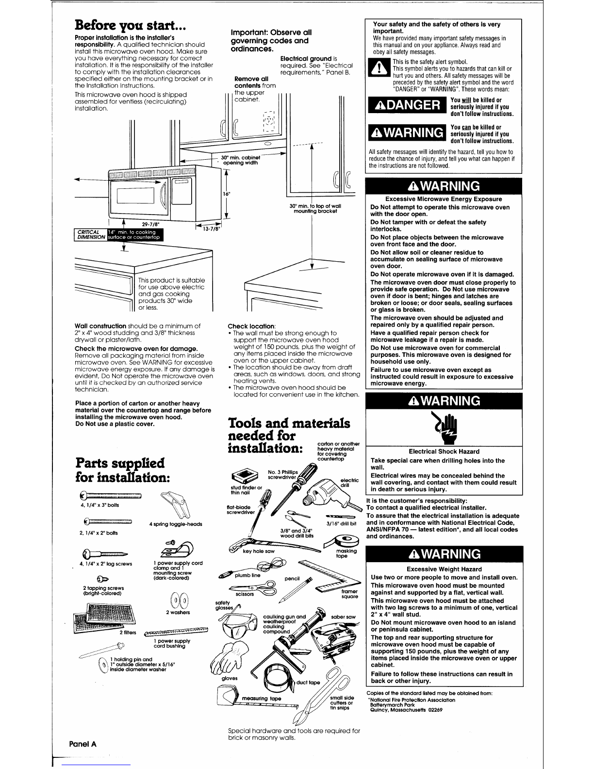
Before you start...
Properinstallation
is
the installer's
responsibility.
A qualifiedtechnicianshould
installthis microwaveoven hood.Makesure
Important:Observe all
governing codesand
ordinances.
you haveeverything necessary for correct
Electrical ground
is
installation.Itis the responsibility of the installer required.See "Electrical
to complywith the installationclearances requirements," Panel
B.
specifiedeither onthe mountingbracketor in
Remove
all
the InstallationInstructions.
contents
from
This microwaveoven hood
is
shipped
assembled for ventless (recirculating)
installation.
productis suitable
use aboveelectric
products
30"
wide
Wall construction
should bea minimum of
2"
x
4"
woodstudding and
318"
thickness
drywall or plaster/lath.
Checkthe microwaveoven for damage.
Remove all packagingmaterialfrom inside
microwaveoven.See WARNING for excessive
microwaveenergy exposure.If any damage is
evident, Do Not operatethe microwaveoven
untilitis checkedby an authorizedservice
technician.
Placea portion of carton or another heavy
materialover the countertop and rangebefore
installingthe microwaveoven hood.
Do Not usea plastic cover.
Parts supplied
for instdadon:
4,
114
x
3"
bolts
p$J
@
4
spring toggle-heads
2,
114"
x
2"
bolts
4,
114"
x
2"
lagscrews 1powersupply cord
clampand
1
mountingscrew
'ZB
(dark-colored)
2
tappingscrews
(bright-colored)
2
washers
iners
1
power supply
cordbushing
1
holdingpinand
0
1
"
outsidediameter
x
511
6
G
lnsidediameter washer
Check location:
The wall must bestrong enoughto
support the microwave oven hood
weight of
150
pounds, plus the weight of
any itemsplacedinsidethe microwave
oven or the uppercabinet.
The locationshould beaway from draft
areas, such as windows, doors, and strong
heatingvents.
The microwave oven hoodshould be
locatedfor convenient use inthe kitchen.
Tools and materials
needed for
cartonor another
ins
t
allation:
pcy.z;ial
311
6
drill bit
a
318"
and
$14"
u
.
.
.
~.
wood drillbits
masking
tape
square
Your safety and thesafety of others isvery
important.
We
have
provided
many
important
safety
messages
in
this manual
and
on
your
appliance.
Always
read
and
obey
all safety messages.
This is the safety alert symbol.
This
symbol
alerts
you
to
hazards
that
can
kill
or
hurt
you
and
others.All safety
messages
will
be
preceded
by
the
safety
alert symbol
and
the
word
"DANGER"
or
"WARNING".
These
words
mean:
You
will
be
killedor
seriously injured
if
you
don't
follow
instructions.
You
can
be
killedor
seriously injured
if
you
don't
follow
instructions.
All
safety
messages
will identify the
hazard,
tell
you
how
to
reduce
the
chance
of
injury,
and
tell
you
what
can
happen
if
the
instructions
are
not
followed.
ExcessiveMicrowaveEnergy Exposure
Do Notattemptto operate this microwaveoven
with the door open.
Do Nottamper with or defeat the safety
interlocks.
Do Not placeobjects betweenthe microwave
ovenfront face andthe door.
Do Not allow soil or cleaner residueto
accumulateon sealing surface of microwave
ovendoor.
Do Not operatemicrowaveoven if itisdamaged.
The microwaveovendoor must close properly to
providesafe operation. Do Not use microwave
oven if door isbent; hinges and latches are
broken or loose; or door seals, sealing surfaces
or glass is broken.
The microwaveoven should be adjusted and
repairedonly by aqualifiedrepair person.
Haveaqualified repair person check for
microwaveleakage if a repair ismade.
Do Not usemicrowave oven for commercial
purposes.This microwaveoven isdesignedfor
household use only.
Failureto use microwaveoven except as
instructedcouldresult inexposureto excessive
microwaveenergy.
24
*
Electrical Shock Hazard
Take special carewhen drilling holes intothe
wall.
Electrical wires may beconcealedbehindthe
wall covering, andcontact with them could result
indeathor serious injury.
It isthe customer's responsibility:
To contact aqualified electrical installer.
To assurethat the electrical installation isadequate
and inconformancewith National Electrical Code,
ANSIINFPA
70
-
latestedition*, and all localcodes
andordinances.
ExcessiveWeight Hazard
Usetwo or more peopleto moveand install oven.
This microwaveoven hood must be mounted
against and supported by aflat, vertical wall.
This microwaveoven hood must beattached
withtwo lagscrews toa minimum of one, vertical
2"
x
4"
wall stud.
Do Not mount microwaveoven hoodto an island
or peninsulacabinet.
The topand rear supporting structure for
microwaveoven hoodmust be capableof
supporting
150
pounds, plusthe weight of any
items placed insidethe microwave ovenor upper
cabinet.
Failuretofollow these instructions can result in
backor other injury.
Copiesof the standard listedmay beobtainedfrom:
"NationalFire ProtectionAssociation
BatterymarchPark
Quincy, Massachusetts
02269
Specialhardwareandtools are requiredfor
brickor masonry walls.
Panel
A
Electrical
requirements
blll
*
ElectricalShock Hazard'
Electricallyground microwaveoven hood.
Do not usean extension cord.
Failureto follow these instructions could
result indeath, fire, or electrical shock.
If codes permit anda separate groundwire is
used,it is recommendedthat a qualified
electrician determine that the ground path is
adequate.
Do not groundto a gas pipe.
Checkwith a qualified electrician if you are
notsure microwave oven hood is properly
grounded.
Do not havea fuse in the neutralor ground
circuit.
A 120-volt,60-Hz, AC-only,
13
or 20-ampere,
fused electricalsupply (locatedintheupper
cabinetas close as possibletothe microwave
ovenhood) is required.Atime-delayfuse or
circuit breaker
is
recommended.It
is
recommendedthat aseparate circuit
serving only this appliancebeprovided.
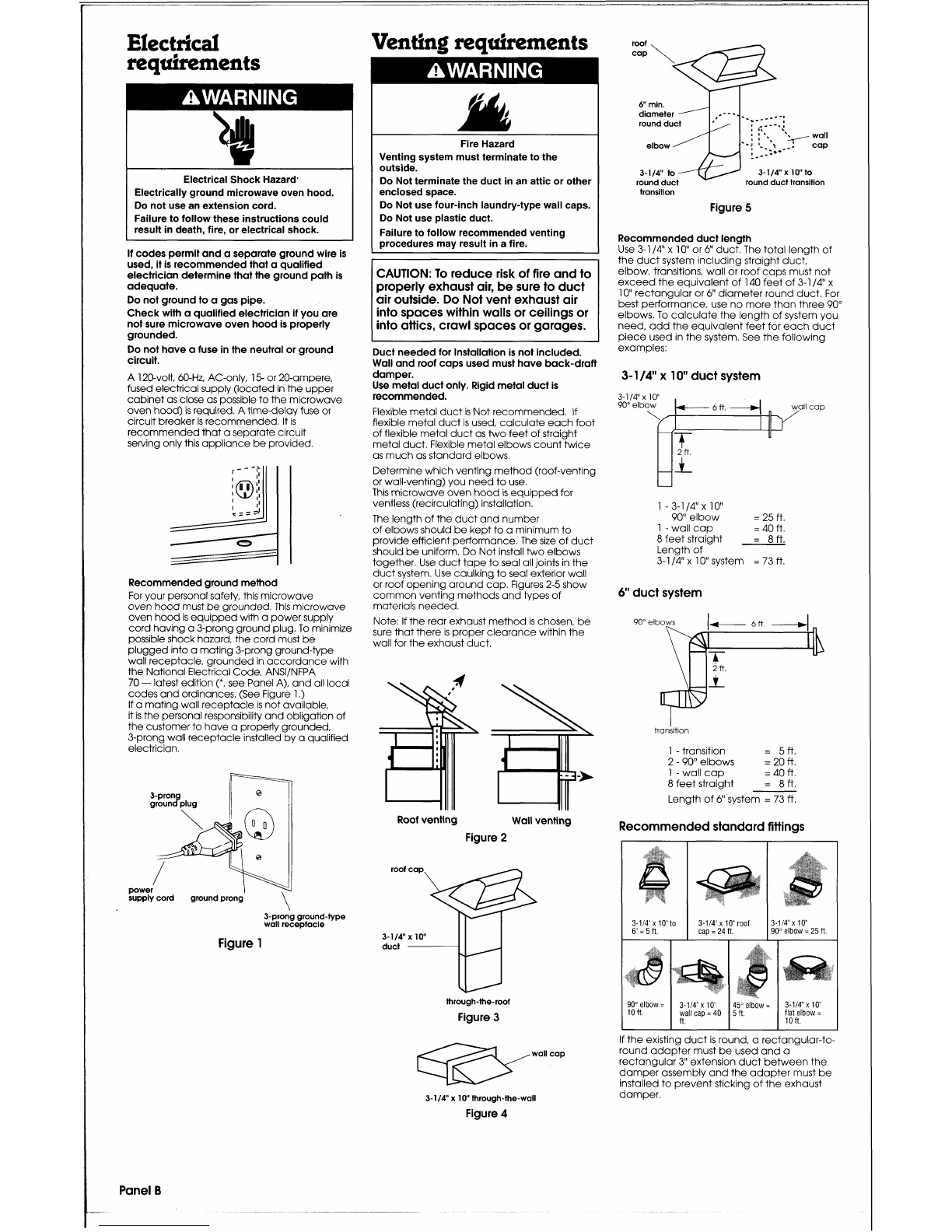
Recommendedground method
For your personalsafety, this microwave
ovenhoodmust begrounded.This microwave
oven hoodis equippedwith a powersupply
cordhavinga 3-prongground plug.To minimize
possibleshock hazard, the cordmust be
pluggedintoa mating3-prongground-type
wall receptacle,groundedinaccordancewith
the NationalElectricalCode, ANSIINFPA
70
-
latestedition
(*,
see PanelA), andall local
codesandordinances.(See Figure
1
.)
If
a matingwall receptacle
is
notavailable,
itis the personal responsibilityandobligationof
thecustomer to havea properly grounded,
3-prongwall receptacleinstalledby a qualified
electrician.
cord ground prong
3-prongground-type
wall receptacle
Figure
1
Fire Hazard
Venting system must terminate to the
outside.
Do Not terminate the duct in an attic or other
enclosed space.
Do Not usefour-inch laundry-typewall caps.
Do Not use plastic duct.
Failureto follow recommendedventing
procedures may result ina fire.
I
CAUTION:To reduce risk of fire and to
properly exhaust air, besure to duct
air outside. Do Not vent exhaust air
into spaces within walls or ceilingsor
into attics, crawlspaces or garages.
-
--
Duct neededfor Installationis not included.
Wall and roofcaps used must haveback-draft
damper.
Use metalduct only. Rigid metal duct is
recommended.
Flexiblemetalduct is Not recommended.
If
flexible metalduct
is
used, calculateeachfoot
of flexible metalduct as two feet of straight
metalduct.Flexible metalelbows count twice
as muchas standard elbows.
Determinewhich venting method(roof-venting
or wall-venting)you needto use.
This microwaveovenhoodis equippedfor
ventless (recirculating)installation.
The lengthof the ductand number
of elbowsshould be keptto a minimumto
provideefficient performance.The size of duct
should beuniform.Do Not installtwo elbows
together.Use ducttape to seal alljoints inthe
ductsystem.Use caulkingto seal exterior wall
or roof openingaround cap.Figures2-5 show
commonventing methods andtypes of
materialsneeded.
Note:
If
the rear exhaust method is chosen, be
sure thatthere
is
properclearance within the
wall for theexhaust duct.
Roof venting Wallventing
Figure
2
roof cap
3-114"
x
lo"
duct
v
through-the-roof
Figure
3
diameter
.----I
round duct
.
-
n
.----.a
:
:,
'.
I
I
*,
+-
wall
elbow
-->
,
I-
-
COP
-*--
3-114" to 3-114"
x
10to
round duct transition
transition
Figure
5
Recommendedduct length
Use 3-114"
x
10
or
6"
duct.The totallengthof
the ductsystem including straight duct,
elbow, transitions, wall or roof caps must not
exceedthe equivalentof 140 feet of
3-1
14"
x
10"rectangularor
6"
diameter roundduct.For
best performance, use no morethan three 90"
elbows.To calculatethe lengthof system you
need,addthe equivalentfeetfor each duct
pieceused inthe system.See the following
examples:
3-
114"
x
10
duct system
1
-
3-114
x
10"
90" elbow
=
25
ft.
1
-
wall cap
=
40
ft.
8
feet straight
=
8
ft.
Lengthof
3-
1
14"
x
1
0"system
=
73
ft.
6"
duct system
transition
1
-
transition
=
5
ft.
2
-
90" elbows
=
20
ft.
1
-
wall cap
=
40
ft.
8
feet straight
=
8
ft.
Length of
6"
system
=
73
ft.
Recommendedstandard fittings
If
the existingduct
is
round, a rectangular-to-
wall cap
roundadapter must be used anda
rectangular
3"
extensionduct betweenthe
damper assembly andthe adapter must be
installedto preventsticking of the exhaust
3-114"
x
10
through-the-wall
damper.
Figure
4
Panel
B
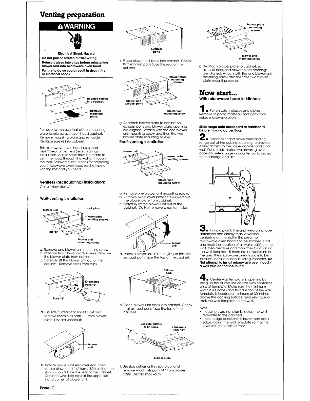
Venting preparation
la
*
ElectricalShock Hazard
Do not pullor stretch blower wiring.
Reinsertwires into clips before reinstalling
blower unit into microwave oven hood.
Failureto do so could result in death, fire,
or electrical shock.
.
blower
late
ports
\
blower unit
mounting screw
f.Placeblower unit back into cabinet.Check
that exhaust ports face the rear of the
cabinet. g.Reattachblower plateto cabinet, so
exhaust ports and blower plate openings
are aligned.Attachwith the one blower unit
mountingscrew andthenthe two blower
plate mountingscrews.
-
\
blower plate
mounting
screws
Replacescrews
Now
start...
With microwavehood in kitchen.
1
H
Put onsafety glasses andgloves,
blower unit
mounting screw
Removeshipping materialsandparts from
inside microwaveoven.
Reattachblower plateto cabinet so
exhaust ports and blower plateopenings
are aligned. Attachwith the one blower
unit mountingscrew andthen the two
blower plate mountingscrews.
Roof-ventinginstallation:
Slide rangeonto cardboardor hardboard
before moving across floor.
Removetwo screws that attach mounting
plateto microwave ovenhoodcabinet.
Remove mountingplateandset aside.
Replacescrews intocabinet.
2
H
Disconnectand movefreestandina
range out of the cabinetopeningto prohe
easier accessto the upper cabinetand back
wall.Put a thick, protective covering over
cooktop, set-inrangeor countertopto protect
from damage anddirt.
This microwaveoven hood is shipped
assembled for ventless (recirculating)
installation.Adjustments must bemadeto
vent the hoodthrough the wall or through
the roof.Followthe instructions for preparing
your microwaveoven hoodfor the type of
venting methodyou need.
mountingscrews
blower unit
mounting screw
Ventless (recirculating)installation:
Goto "Now start..
."
a.Remove one blower unit mountingscrew.
b.Removetwo blower platescrews.Remove
the blowerplatefrom cabinet.
c.Carefullylift the blower unit out of the
cabinet. Do Not removewires from clips.
Wall-venting installation:
mountingscrews
blower unit
mounting screw blower
unit
Using a plumb lineand measuringtape,
determineand clearly mark a vertical
centerlineon the wall inthe area the
microwave oven hood
is
to beinstalled.Find
andmark the locationof all wall stud(s) onthe
wall; then measure and mark their locationon
the wall template.
If
there are nowall studs in
the area the microwaveoven hood
is
to be
installed, consult a localbuilding inspector.
Do
Notattempt to installmicrowave oven hoodif
a wall stud cannot befound.
a.Removeone blower unit mountingscrew.
b.Remove two blower platescrews. Remove
the blower platefrom cabinet.
c.Carefully liftthe blower unit out of the
cabinet. Removewires from clips.
d.Rotateblower unit
114
turn (90") so thatthe
exhaust ports face the top of the cabinet.
exhaust
/
ports
4
Center wall templatein openingby
liningupthe plumb line on wall with centerline
onwalltemplate.Makesure the minimum
width is 30 inchesandthat the top of the wall
templateis located a minimum of 30 inches
abovethe cookingsurface.Securely tape or
tack the wall templateto the wall.
Parts
"B
w
e.Place blower unit back into cabinet.Check
that exhaust portsface the top of the Note:
cabinet.
If
cabinetsare not plumb, adjust the wall
templateto the cabinets.
If
front edge of cabinet
is
lower than back
Use side cutters
edge, adjust the wall templateso that it is
or tin snips. Knockouts
levelwith the cabinetfront.
I
Parts
"A"
d.Use side cutters or tinsnips to cutand
removeknockoutsparts
"B"
from blower
plate.Discardknockouts.
blower plate
e. Rotate blower unit endover end.Then
rotateblower unit
112
turn
(1
80") so that the
exhaust ports face the rear of the cabinet.
Replacewires into clips atthe upper left-
handcorner of blower unit.
f.Use side cuttersor tin snips to cutand
removeknockouts parts
'A"
from blower
plate.Discardknockouts.
Panel
C

Numbers
correspond
to
steps.
8
r
cabinetframe. Trim the edges
"A",
'B"
and
'C" on the uppercabinettemplate so that
thetemplate will fit onthe bottom of the
uppercabinet. If uppercabinet has a
recessedframe, trim template so that itfits
insidethe recessedarea.Align the centerline
of the uppercabinettemplate with the
centerlineof the wall template; then securely
tape or tack the uppercabinettemplate in
place.
24
*
ElectricalShock Hazard
Take special carewhen drilling holes into
the wall.
Electricalwires may be concealed behind
the wall covering, and contact with them
could result indeath or serious injury.
6
rn
Findthe ~ointsonthe wall temolate
labeled 'D",
'E",
"F",
and
'G".
Drilla
3/16"
diameterhole atthe pointsthat are over a
wall stud and a 314" diameter holeatthe
pointsthat are over drywall.
9
rn
Drill a 3/8"hole at ~oints
"J",
*K",
and
"N"
onthe upper ~abinet'tem~late.
G
--!
+a~~r~~a~b~~b~+v-iba~~-tbg~bb~i-b4i~a~~~
I
7
rn
Locatethe wall stud closest to the
center of the areas marked
'H"
and 'I" onthe
wall template..Drill 3/16" holes intothe wall
stud ineach of the areas.If a wall stud
is
not
locatedwithin these areas, drill314" diameter
holes nearesttothe center of the areas as
possible.
If there is not a wall stud within the areas
marked
"H"
and "I"and not behind points
marked
"D",
'E",
"F"
and
"G",
DO
NOT
install
microwaveoven hood.(Consult building
inspector.)
Za
*
ElectricalShock Hazard
Installpower supply cord bushing around
hole drilled in metal cabinet.
Failureto do so could result in death or
serious injury.
8
rn
cutout or drill a
21'
diameterhole atthe
area marked
'M",
'power supply cordhole"
onthe uppercabinettemplate. If upper
cabinet
is
metal, install powersupply cord
bushing aroundthe edge of holeto prevent
damageto the cordfrom the rough metal
edge.
Removethe upper-cabinet and wall
templates.
uppercabinet bottom filler block
\
/
masking tape
If bottomof upper cabinet is recessed,
2"
x
2"
filler blocks(not included) the same
recessthickness as the upper cabinet will be
needed.Markthe center of eachfiller block
anddrill a 318" diameter hole atthe marks.
Align filler blocksover the two holes
"J"
and
'K"
inthe cabinet bottom andattach to
cabinet bottomwith maskingtape.
1
0
rn
Determinewhich venting method
(roof-venting,wall-venting, or ventkss) you
needto use.This microwaveoven hood
is
manufacturedfor ventless (recirculating)
installation.Makeadjustments to microwave
oven hoodif wall- or roof-ventinginstallation
is
needed.See 'Venting preparation," PanelC.
1
1
rn
For ventless installations,
go to Step
14.
To vent through the roof,
cutoutthe rectangular
area marked
'L"
onthe upper cabinet template.
To vent throughthe wall,
cutout the rectangular
area marked
"0"
on the wall template.
C-
Panel
D
-
-
-
--
-

r
--
--
-
-
--
-
--
---
-
-
I
2
w
ROO^
venting:
DO
~otinstall
I
6
w
Slide
holding
2
1
.
Remove holdingpinandwasher. If
ductworkatthis time.Go to Step
14.
washer onto holding wall-ventingor ventless installation
is
used, go
pinandset inside
washer
Step
24.
Wall venting:
Installductwork through thevent cabinet.
openinginthe wall. Completethe venting
system throughthe wall accordingtothe
pin$
methodneeded.See "Ventingrequirements"
and "Ventingpreparation," Panels
B
andC.
Use caulkingto seal exterior wall opening
around exhaust cap.
I
3.
If wall-
venting installation is
used,
attach damper
to rear of mounting
plate.Align 3-1
14"
x
10"
duct with damper and
see that damper
Excessive Weight Hazard
Usetwo or more peopleto move and install
microwave oven hood.
Lift microwaveoven hood and hang on
support tabs on bottom of mounting plate
brackets.Hold microwave oven hood in
placeand secure to upper cabinetwith the
holding pin and washer.
Failureto follow these instructionscan
result in back or other injury.
P
-
22
w
Roof-ventinginstallation:
Align the
damper/ductconnector with the vent ontop
of the microwaveoven hood.Dampershould
beontop of tab. Use two tapping screws
(bright-colored)to attach damper/duct
connectorto the microwaveoven hood
Note:Damperlductconnectormust be
movesfreely. attached to mlcrowaveoven hood
after
mlcrowaveoven hood
is
installed.
power
supply
cord
clamp
23
Roof-ventinginstallation:
Installduct
throughthe vent opening in the upper
1
7
w
CarefullyliftmicrowaveOven hood cabinet,Complete+heventing system
and hang it on supporttabs at the bottom of throughthe roof accordingto the method
1
4
w
Insertlagscrews (wallstud) or the mountingplate.Thread Power supply cord needed.See "Venting
requirements"
and
toggle bolts(drywall) through the holes on through the power supply cordhole in the "Venting
preparation,"
Panels
B
and
C.
Use
the mountingplatewhere the mounting bottomof the upper cab~net. caulking to seal exterior roof openingaround
platewill beattachedtowall stud or exhaust cap.
drywall at holes
'D",
'E",
'F",
'G"
.
'H"
and
'I".
I
8
w
Rotate microwaveoven hood
upwardso that top of hoodis against bottom
mountingplate to end
24
install
power supply cordclamp,
of upper cabinetor cabinetframe using screw as shown in Step 23, to inside of
the cabinet.Use power supply cordclampto
bundlethe power supply cord.
0
25
w
Grasp filter screen with one hand
holdingthe ringandthe other handholding
the oppositeend, Insertthe end of the filter
screen without ringintothe opening andslide
towards the center of the microwaveoven
Attach a spring toggle headto the end of hood.Insert ring endof filter screen intothe
eachtoggle bolt.Leave at least one wall opening andslide entire screen towards the
thickness of space betweenthe mounting side of the microwaveoven hooduntilscreen
plateandthe end of the springtoggle
1
9
Dropthe holdingplnzdwasher is securely in position.Repeatfor other filter
headso that the spring toggle headcan assembly into hole 'N" and push pindownas screen
properlyopenon the other side of the wall. far as itwill go.
2
6
Plug in the power supply cord.
15
Posltlonmountlng
plateon the wall
2
7
w
Readyour Use and CareGuide,
then check the operationof your mlcrowave
makingsure that
topof mounting oven hood.
plateis against
bottomof
plate is against bottom of
cabinet or
cabinetor cabinet frame.
bottomof
cabinetframe.Start the lagscrews through
thewall-stud holes and/or insert togglebolts
andsprlng toggleheadsthrough drywall
oven hood.To get the most efficient
holes.Tighten screws and/or boltsto secure
use from your new microwave
mountingplate to wall. Check that center
2
0.
Placewashers over two,
114"
x
2"
or
3"
oven hood,readyour Use
&
Care
of bracket
is
securedto wall. bolts.Then inserta boltdown through each
Guide. Keep InstallationInstructions
holein the upper cabinet bottom.Tightenthe
boltsuntilthe gap betweenthe upper cabinet
Congra
tala
tirons!
and microwaveoven hoodis closed.
andGuide close to microwaveoven
Panel
E
r
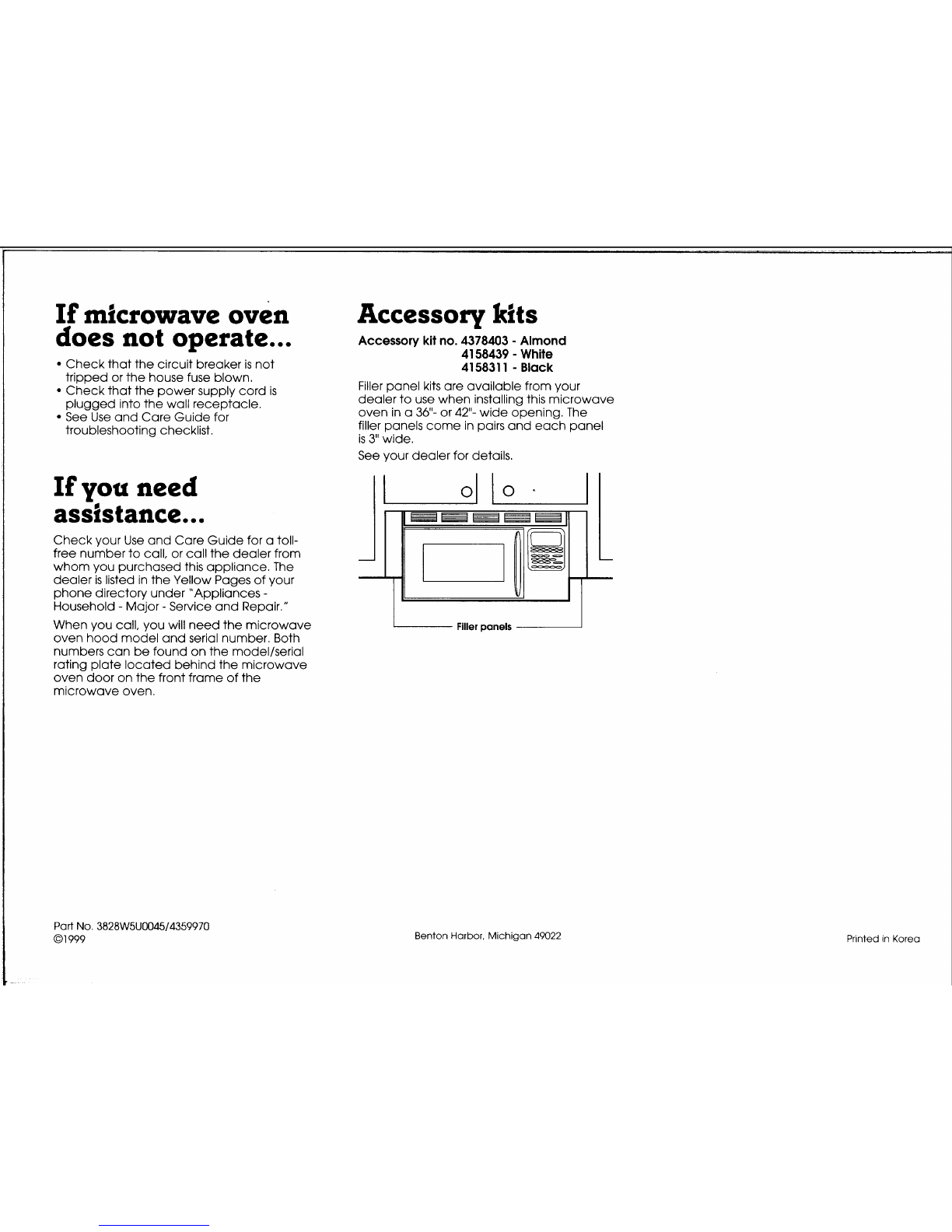
If
microwave oven Accessorv
kits
does not operate
...
Checkthat the circuit breaker is not
L
Accessory
kit
no.
4378403
-
Almond
4158439
-
White
415831
1
-
Black
-
~
---..
tripped or the house fuse blown.
Checkthat the powersupply cord
is
Filler panelkits are availablefrom your
plugged intothe wall receptacle. dealer to use when installingthis microwave
See Use andCare Guide for oven in a
36"-
or
42"-
wide opening.The
troubleshootingchecklist. filler panels come in pairsandeach panel
is
3"
wide.
See your dealerfor details.
If
you need
assistance
...
Check your Use andCare Guide for atoll-
free numberto call, or callthe dealer from
whom you purchasedthis appliance.The
dealer is listedin the Yellow Pages of your
phonedirectory under "Appliances
-
Household
-
Major
-
Serviceand Repair."
When you call, you will needthe microwave
.
...
-.
.-------
ovenhoodmodelandserial number.Both
numberscan befound on the modellserial
ratingplate locatedbehindthe microwave
ovendoor on the front frame of the
microwaveoven.
Part
No.
3828W5U004514359970
01
999
Filler nanels
Benton Harbor, Michigan
49022
Printed
in
Korea
Table of contents
Popular Microwave Oven manuals by other brands


Conrad Electronic
Conrad Electronic 2372935 operating instructions

GE
GE Spacemaker JVM1440BH datasheet

DAEWOO ELECTRONICS
DAEWOO ELECTRONICS KOR-6L8K5S83 Operating instructions & cook book

DAEWOO ELECTRONICS
DAEWOO ELECTRONICS KOR-1N5A9S Operating instructions & cook book

Daewoo
Daewoo KQG-6617G Operating instructions & cook book

Samsung
Samsung M1779 Owner's instructions

 Operating and installation instructions")


