BERGER MEGA POINT User manual

BERGER AG • Dept. Bohrerschleiftechnik
C.F.L. Lohnerstrasse 28E • CH-3645 Gwatt/Thun
Telefon +41 (0) 33 336 15 66 • Telefax +41 (0) 33 336 16 66
UNIVERSAL OPTICAL DRILL GRINDING MACHINE
OPERATING INSTRUCTIONS

Universal Optical Drill Grinder
Operator's Manual Issue 06/01 Rev 02 I
Contents
Safety instructions
General safety instructions .............................................................................................................. 1
This is the symbol for your safety .................................................................................................... 1
Protective devices ........................................................................................................................... 1
Safety and accident prevention regulations ..................................................................................... 1
Points to remember when operating MEGA-POINT ........................................................................ 1
General information on MEGA-POINT
General information on MEGA-POINT............................................................................................. 2
Delivery, transportation and installation
Delivery ........................................................................................................................................... 3
Standard with basic machine................................................................................................. 3
Options.................................................................................................................................. 3
Checking the delivery ............................................................................................................ 3
Transportation ................................................................................................................................. 3
Installing the machine...................................................................................................................... 4
Space requirements ..............................................................................................................4
Locationrequirements...........................................................................................................4
Connection ...................................................................................................................................... 4
Electrical connection ............................................................................................................. 4
Connect flexible shaft ............................................................................................................ 5
Dust extraction ...................................................................................................................... 6
Dust collector ........................................................................................................................ 6
Preparing tools ................................................................................................................................ 6
Component discription
Componentdiscription..................................................................................................................... 7
Setup
Basic adjustment for right-hand drills............................................................................................... 8
Completing and using the setup sheet............................................................................................. 8
Contents

Universal Optical Drill Grinder
Operator's Manual Issue 06/01 Rev 02 II
Operating the machine
Switching on the machine - Master switch....................................................................................... 9
Adjusting the angle ........................................................................................................................ 10
Setting the point angle A ..................................................................................................... 10
Adjusting primary cutting angle B1 ...................................................................................... 10
Adjusting secondary clearance angle B2............................................................................. 10
Install collets.................................................................................................................................. 11
Collets MP 6.5 (1.0 to 6.5 mm dia.) ..................................................................................... 11
Collets MP 20 (6.0 - 20.0 mm dia.) ...................................................................................... 11
Swivel arm MP 30 (option) and collets MP 30 (20.0 - 30.0 mm dia.).................................... 11
Chucking drills ............................................................................................................................... 12
Aligning right-hand drillsup to 20 mm dia. ......................................................................................12
Chucking and aligning right-hand drills over 20 mm dia. (MP 30) .................................................. 13
Aligning projection image............................................................................................................... 13
Switch on motor............................................................................................................................. 14
Grinding drills ................................................................................................................................ 14
Indexing cycle ............................................................................................................................... 15
Feed .............................................................................................................................................. 15
Checking ....................................................................................................................................... 15
Shielding from bright outside light.................................................................................................. 16
Point splitting ................................................................................................................................. 17
Procedure ........................................................................................................................... 17
Changing over for special drills
Changing over from right-hand to left-hand drills ........................................................................... 18
Changing over machine ...................................................................................................... 18
Changing over point splitting device .................................................................................... 18
Grinding left-hand drills.................................................................................................................. 19
Aligning the cutting edge for left-hand drills ......................................................................... 19
Point splitting on left-hand drills ........................................................................................... 19
Changing over from left-hand to right-hand drills ........................................................................... 20
Changing over machine ...................................................................................................... 20
Changing over point splitting device .................................................................................... 20
Changing over for 3-lip drills .......................................................................................................... 21
Changing over for flat-bottom drills ................................................................................................ 22
Handling grinding wheels
Mounting Diamond and CBN grinding wheels ............................................................................... 23
Contents

Universal Optical Drill Grinder
Operator's Manual Issue 06/01 Rev 02 III
Cleaning & Maintenance
Cleaning & Maintenance................................................................................................................ 24
Maintenance
Changing the 10x lens................................................................................................................... 25
Focusing the 10x lens ................................................................................................................... 25
Mounting and focusing Zoom Lens................................................................................................ 26
Replacing projection lamp ............................................................................................................. 27
Changing the sapphire lens ........................................................................................................... 27
Changing viewing screen .............................................................................................................. 27
Replacing the fuses....................................................................................................................... 28
Replacing the main fuse ...................................................................................................... 28
Replacing fuse for projection lamp ...................................................................................... 28
Adjusting cutting edge geometry ................................................................................................... 29
Reproducing the factory adjustment ..............................................................................................30
Troubleshooting
General faults ................................................................................................................................ 31
Technical datas
Technical datas ............................................................................................................................. 32
Setup values for different drills
Setup values for different drills ...................................................................................................... 33
Wiring diagram
Wiring diagram .............................................................................................................................. 34
Contents

Universal Optical Drill Grinder
Operator's Manual Issue 06/01 Rev 02 1
Safety instructions
Safety instructions
General safety instructions
General conditions for use of MEGA-POINT:
- MEGA-POINT is only intended for grinding
twist drills, 3-lip drills, carbide drills and flat-
bottom drills.
- The manufacturer is not liable for damage or
accidents caused by improper use.
- The operating, maintenance and repair
instructions in this manual must be observed.
- The machine may only be operated, used,
maintained and repaired by specially trained
personnel.
- The manufacturer is not liable for any
modifications made to the machine by the
customer.
Safety and accident prevention
regulations
Basic regulations
- Check the operation reliability of MEGA-
POINT before every startup.
- The prevailing safety and accident prevention
regulations must be observed in addition to the
instructions contained in this manual.
- Before starting work, make sure you are
familiar with all the devices and controls on the
machine and their functions. It will be too late
during operation.
This symbol marks passages in the manual relating to
safety for man and machine.
Protective devices
All protective devices integrated in or added to the
machine are intended for your safety. They must be
kept in their original condition and must be maintained
and tested in accordance with the maintenance
instructions.
Points to remember when operating
MEGA-POINT
- Check every time before use.
- Certain jobs can only be performed when the
machine is at standstill.
- Always wear protective goggles when performing
grinding work.
- The point-splitting grinding wheel is automatically
switched on when the swivel arm is moved to the
right.
- Do not dress diamond and Borazon wheels.
- Dismounting: when the feed ring is removed, a
pretension spring inside is released.
- The projection lamp is hot.
- Never touch the glass body of a protection lamp.
- Do not smudge the inside of the sapphire lens.
- Never touch the lined side of the viewing screen.
This is the symbol for your safety

Universal Optical Drill Grinder
Operator's Manual Issue 06/01 Rev 02 2
General information on MEGA-POINT
The MEGA-POINT Universal Optical Drill Grinding Machine is designed for the precision grinding of all
types of drills. The cutting edge can be precisely aligned and checked for quality after grinding using optical
aids.
The primary cutting angle, the secondary clearance angle and the point angle are freely adjustable.
In order to optimize the angles for machining different materials, the required values are listed in tables on
the last page.
In addition to grinding the cutting edge, MEGA-POINT offers a device for point-splitting facility in the same
fixture. Here, too, a wide variety of point-splitting types can be adjusted depending on the requirements.
IFANGER inside turning steels of types ABS and ECS can be perfectly reground using an add-on unit
(option).
General information on MEGA-POINT

Universal Optical Drill Grinder
Operator's Manual Issue 06/01 Rev 02 3
Delivery, transportation and installation
Delivery, transportation and installation
Delivery
Check the delivery consignment using the list below (check that options are identical with the purchase
order):
Standard with basic machine
1 MEGA-POINT Universal Optical Drill Grinding Machine, comprising:
2 CBN grinding wheels (1 x Ø 125 mm; 1 x Ø 50 mm)
2 Collet chucks for drill Ø 1-6.5 mm and Ø 6-20 mm (0.040 - 0.250" and 0.250 - 0.787")
Flexible shaft
Machine lamp
Wrench set
Operator’s manual
Spare parts list
Setup templates
Options
1 Swivel arm MP 30
1 Set of collets MP 30, 5 pieces
1 Machine stand
1 Zoom lens 6 - 20 power
1 Hood
1 Additional loupe
1 Truing diamond
Checking the delivery
Check the delivery consignment on receipt of the goods. Contact the supplier immediately if materials are
found to be missing or defective.
Transportation
The machine weighs about 50 kg / 100 lbs without its stand.
Use a movable base for transportation over long distances. Two people are required to lift the machine onto
the stand or a table.
Universal Optical Drill Grinder
Operator's Manual Issue 06/01 Rev 02 4
Connection
Electrical connection
Note the information on the nameplate at the machine rear.
220 V, 50 Hz or
110 V, 60 Hz
Installing the machine
In order to work optimal with MEGA-POINT, the following requirements must be met.
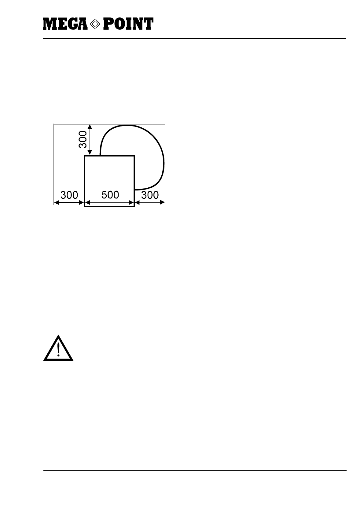
Space requirements
The minimum distances indicated in the drawing must be kept.
Location requirements
MEGA-POINT on stand (option)
The stand must be placed on a level, hard surface.
Make sure that the stand has a firm footing and does not wobble.
MEGA-POINT without stand
A steady table is sufficient as a surface. Make sure that the machine has a firm footing and does not wobble.
To ensure good ventilation of the machine, do not place it on a soft surface (foam).
Delivery, transportation and installation

Universal Optical Drill Grinder
Operator's Manual Issue 06/01 Rev 02 5
Delivery, transportation and installation
Connect flexible shaft
The flexible shaft drives the point-splitting grinding
wheel.
- Connect end 1 to coupling flange on rear of
machine.
- Connect end 2 of flexible shaft to coupling piece of
point-splitting device.
- Relieve load on flexible shaft.
Do not connect when twisted.
- Tighten nuts.

Universal Optical Drill Grinder
Operator's Manual Issue 06/01 Rev 02 6
Dust extraction
The MEGA-POINT can be connected to a central dust
extraction system.
Connection: 38 mm dia.
Dust collector
However, the machine is also prepared for connection
to a standard industrial vacuum cleaner. A vacuum
cleaner can be connected to the machine as follows:
- Connect vacuum cleaner power cord to socket at
machine rear.
- Connect cable according to electrical diagram on
page 38.
The vacuum cleaner is now connected in such a way
that it starts together with the grinding motor.
Delivery, transportation and installation
Machine lamp (optional)
- Attach the 6V/10W machine lamp, article number
976 009 (optional), to the right side of the machine
using the supplied holder.
- Insert the cable into the housing through the desig-
nated opening and seal with a gland.
- Connect cable according to electrical diagram on
page 38.
Preparing tools
Unpack and clean the supplied tools.
All tools must be dried before use. Grinding dust
sticks to wet, oily tools and can damage them.
Table of contents


