Berkey OXBERRY Filmaker 5332-00 User manual
VOOQ
532P-00
□
XBERRY
Filmaker
16mm
Animation
Stand
and
Camera
31.00
each
(q.mlity
tiiscourts)
918--C0e3
3-68-SV
OXBERRV
PRODUCTS
Optical
Printer
Series
5117
Speaa
Effects
Step
Printer
with
automat
e
focus,
automatic
ds-
solve
and
fade,
mu
ti
speed
drive
for
35mm
and
IG-
m
5
Models
ovailabte
Model
5117
00
Ma
n
p'OioctO'
head
(sing’o
head)
Modal
5117-20
Aerial
mage
and
mam
projector
hoad
(double
head)
Meant5117-20
Beam
splitter
end
man
p'o.ector
hoas
(double
head)
Modal
5117-70
Aonol
.mage
beam
splitter
ard
mam
projecto
head
(trip!©
hoed)
Model
511
7-BO
Ac-iol
mage,
beam
splitter,
beam
sp
tter
sent
imago,
and
mom
projector
hoed
(guud'uplo
head)
0111
Step
Printer
for
t
1
35mm
to
35mm.
35mm
to
16mm
and
cireirv
9COQO
conversion
Also
for
2:1
enlargement
and
reduction.
Master
Series
Stands
and
Cameras
Modal
5442
Animation
Stond
with
X
V
lens
mount
Underneath
Acne
meg©
Pro.ecton
Hoad
Mode
5443
Project
on
Filmstrip
Stand
(fixed
'eg
St'at
on
f
m
movement)
Mode!
5*20
Process
Carrera
35/16
(fixed
registration
f
m
movement)
Filmaker
Series
Mode!
5332
Ammut
on
Stand
(covered
in
this
manual)
Ammot
on
Registration
Dev
ces
Mode
5333
Filmstrip/Slide
Stand
(sec
rsidc
bock
cover)
OXBERRY
Filmaker
16mm
Animation
Stand
and
Camera
INSTRUCTION
MANUAL
for
OXBERRY
Filmaker,
Model
5332-00
BERKEY
TECHNICAL
25-15
50th
STREET.
W00DSIDE.
N.
Y.
11377
•
TELEPHONE:
(212)
932-4040
*
DlV
SION
Ct
r=-*
Berkeyte.
Photo
Inc
Lh

Purpose
The
one
product
is
the
ceveloped
him.
The
cond
tions
necessary
fc-
'.he
dcs-cd
nrd
(sconomicully
feasible
end
product
r.ust
be
predictable
and
controllab’e
by
she
producer.
This
unit
gives
the
producer
the
ab
ty
of
complete
y
contro
img
:ne
rela-
tlonship
between
tho
film,
lens
and
copy
during
phetug-uphy.
with
pred
ctabo
results
and
o
minimum
of
effort.
Animation
is
the
-esu
t
of
the
photographer's
ability
to
photograpn
the
artwork
and
ces
in
tho
relationships
necessary
for
ore
movement
to
flow
smoothly
into
another
The
key
so
thaS
ability
is
"registration
"
It
is
this
unit's
ab
.ity
to
r&rv.u
n
registration
that
allows
tho
photogrophor
to
position
cels
for
smooth
movement
devoid
of
"jumping"
of
the
projectec
image
on
the
screen.
Registration
is
assurec
by
she
pegs
in
each
peg
track
on
the
table
top
Replacing
one
cel
with
another
on
the
pegs
will
insure
that
the
new
cel's
position
relat-ve
to
the
camera
will
=e
t-.e
same.
This
registration
is
maintained
also
in
the
care-a
by
the
intermittent
registration
pin
that
rogisters
tho
film
in
the
aperture
and
by
tho
keyed
column
that
allows
ve-
movoment
of
the
camera
and
the
Ions
in
registration
to
the
compound
However,
the
registration
maintained
during
the
pholog-aphy
w
only
be
as
good
as
that
maintained
during
tho
exocut
on
of
the
artwork
The
OXBERRY*
col
pure!,
and
drawing
disc
described
in
shio
manual
are
for
tho
purpose
of
insur
ng
that
oJ
registration
will
moot
tho
neods
of
the
an
mato'
during
photography
Among
conditions
controlled
by
this
unit
ure
the
following
Tho
diotonco
from
sho
Mm
to
tho
copy
(Reduction
Rot
o)
Tho
Focus
Tho
frame
sue
Tho
number
of
fromoa
In
soguonce
Tho
mco'porntod
copy
in
any
photogroph
Tho
orlonsatlon
of
tho
copy
(registration)
The
exposure
time
Tho
dlroctlon
of
advance
Tho
number
of
times
one
frame
is
exposed
Seme
of
the
conditions
contro
od
may
bo
modi'
ed
on
this
unit
at
tho
optic-
o'
Iho
oporotor
Tho
d
8p!acement
of
the
copy
(pars,
t
Its
or
spins)
Tho
piano
of
focus
Tho
oxposuro
time
Tho
addition
of
filters
Tho
Ions
"f”
stop
soiling
Lighting
Those
conditions
not
directly
involved
;n
film
exposure
have
to
be
cc-t-c
ed
sepa¬
rately
from
tho
umt
Tho
type
of
fi’m
used
The
type
and
size
cf
the
copy
Tho
top
I
ghting
fo-
photographing
opaque
copy
Manner
of
film
developing
Table
of
Contents
Introduction
PjrpcsC
1.0
Camera
U
Film
1.1
I
Loading
1.1.2
Threac
r.g
1
2
Film
Advance
(Stop
Mol
on
Motor)
1
3
Sequence
Control
1.4
Exposure
Control
1.5
End
of
F.lm
Indication
1.6
Film
Take-Up
1.7
Camora
Activation
7
0
Stand
2
\
Copy
Mounting
7
7
Focus
Mochonlom
2
3
Camora
Positioning
2
4
Ret
clo
Projection
3
0
Controls
(Console)
3.1
Film
Exposure
(Faooa
&
Dissolves)
3.2
Film
Advance
3
3
Framo
Counter
3.4
Si*
ng
4
0
Lighting
4.:
Top
Lighting
4?
Under
Lighting
4
3
Ir.s
Sett
ng
5
0
Maintenance
of
Equipment
6
0
Interehangoiitiility
w,th
5327-01
Filmstrip/Slide
Camera
7
0
tnst/v'arion
‘ntormohon
8.0
Glossary
9.0
Schematics
Accessories
1
1
4
Maga*me.
4C0
ft
2.1
8
Float
ng
Platen.
12
fie
d
2
1
9
Float
ng
Pegs
2.1
13
Under:
ghting
Unit
3
22
Seguerce
Centro-Counter
3.3.2
H
and
Control
for
Exaosu-e
and
Sizing
3.33
Hotoscose
Accessories.
(Conl'd)
Registration
Dev
ces-
2
1
10
Drawing
Disc
2.1
I
t
Field
Gu
de
2.1
12
Punch
Photogrnph
r.
Fig.
1
Overall
Stand
Fig.
2
Cumin
j
Removal
Fig.
3
Camera
Prepared
lor
Threading
Fig.
4
Lifting
RogiSt'Ot
on
P
n.
Fig
5
Manually
Tranoportlng
Film
"ig
6
Auxiliary
Sh
utter
Control
Fig
7
Tablo
Top
Fig.
8
Placing
Cel
on
Peg
Track
Fig
0
Art
Work
Positioned
for
Photography
Fig.
10
Floating
Png
1
.
Fig.
11
Drawing
Disc
F
g.
12
Field
Guide
Fig.
13
Punch
F
g.
14
Undorlightlng
Unit
F
g
15
Focuolng
Knob
F
g.
16
Light
Projector
Poalhonii
Fig.
17
Control
Panel
Fig
18
f
ade.
Disaoivo
Curvo
ond
Camora
Scale
Fig.
19
Reticle
Fig
20
Hand
log
Fig.
21
Rotoocope
Fig
22
Iris
Ring
Fig.
23
5327-01
Filmstrip/Slide
Camora
Fig.
24
Comb
nation
Control
Pare
Fig
?5
Installation
Drawing
Chart
1
Shutter
opening
Inside
Rack
Cover
—
5333-00
Filmstr
p
Slide
Stand
Back
Cover
—
Typical
Installation
of
5332-00
Schematics;
5326-01
Camora
Circuit
Zoom.
Viewer
and
Underhghtirg
Circu
t
5326-27
Combination
Camera
Circuit
1
mer
C
rcu
t

1.0
Camera
CAMERA
STOP-HIGH
SHAD0W80ARD
ZOOM
LIMIT
STOP
LOW
CON
IIIOL
CONSOLE
COMPOUND
PLATEN
AND
PEC
TRAC
KS
PANTOGRAPH
I?
FIELD
PEC
TRACK
CONTROLS
AUXILIARY--
SHUTTER
CONTROL
pnoircnoN—.
I
AMP
(COVER
PHOIOGRAPM
SHOWS
EYEPIECE
IN
PLACE)
COUNTER
1.1
Film.
This
camera
is
built
to
accopt
a
100'
or
200’
reel
of
day!
ght
load.
16mm
Mm.
single
or
double
pc-doretcd.
1-1-1
Loading:
If
i
is
desirable
to
load
or
unloud
the
camera
in
a
dark¬
room.
removal
of
the
camera
from
tho
stand
is
accomplished
In
the
follov.-
ng
manre':
a)
First
disengage
the
electrical
connector
attached
to
the
top
of
the
cnmora.
(See
F
g.
?a)
Rotate
tho
knurled
portion
of
tho
connoctoi
counterclockwise
until
t
<s
leieased
and
then
suit
the
connector
away
from
tho
camo'd.
figure
'a.
Tterr.ovirr
Klwtrical
Connector.
t>)
Release
the
ocking
lever
(See
f
ig
?2)
maintain
ng
tho
comeio
In
position
c)
Rotato
-no
came'a
45'
ond
pick
II
up
out
of
tho
boyoncil
slot
When
reroving
car-
e-.i
'rom
stand
after
photography,
cover
opening
on
Iho
bottom
with
hand
This
will
provent
any
oxtronoouo
light
from
entering
camera.
(Sec
Fig.
2b).
112
Th'oadng
fheie
Is
a
chart
located
on
tho
back
of
tho
camera
cover
Th
o
chart
thould
bo
followed
exactly
.-.lion
threading
the
Comoro.
The
chart
shows
two
methods
of
th-ead
ng.
One
method
is
followod
whon
tho
camca
is
equipped
with
a
magazine
and
shows
tho
film
commg
from
tho
top
center.
Tho
second
method
of
threading
shown
is
used
whon
th.*
film
is
loaded
directly
into
tho
camera.
Cioaranco
for
thread
ng
the
film
is
made
m
the
following
manner:
(See
Fig
3)
a)
Place
the
power
switch
in
the
off
position.
b)
Remove
the
camera
cover
by
rotating
the
knurled
knob
In
the
center
counterclockwise
until
tho
cove'
is
roleasod.
c’
Ihe
isc'aticr
sprocket
ocatec
just
belo-.v
and
between
the
feed
-nd
t.:<oup
rods
is
exposod
by
rotating
the
knurled
knob
on
the
top
cf
the
gu
de
-o'ler
units
counte-c'ockw
so.
3e
sure
the
sprocket
teeth
enter
the
sorockot
holes
in
the
him
before
'eturnmg
the
guide
•oilers
to
their
original
position.
fi'jiirc
:h,
R
■
mov
i
rijr
earner
a
from
■
land.
li'/urt
I.
Mixli-i
.'iS.12
File
nker
ICmrr.
Ar.:riiiili<i:t
Sl.nn!
..ml

fiyurt
.t
a.
Thread
ini:
diagram.
figure
Sb.
Koir.ovinir
pressure
plnlc.
a)
The
pressure
plate
is
removed
by
King
the
:ever
located
on
the
right
ol
tho
plato
until
the
ploto
dears
tho
slot
and
then
pulling
the
plate
out.
(Soo
Fig.
3).
u)
L
ft
the
sp'.ng
mounting
the
registration
pin
with
fingernt,I
unt
nnough
clearance
is
made
to
elip
thr
film
under
it
Relense
the
spring
and
slip
the
film
along
the
slot
un|B
the
pm
enters
a
sp'oeket
hole
if
necoosnry,
rotate
motor
manually
until
clow
pm
19
raised
(Soo
Fig.
5).
Kiur*
{.
Lifting
intermittent
reiri«*-nition
Pin
to-irra
:<an«rii
:
:.3
f.'.afiual
hi!m
Transport:
By
rotating
the
knob
located
on
top
of
the
step
motion
motor,
the
f
m
w
II
be
transported
and
can
be
checked
•o'
proper
threading.
This
can
only
be
done
with
the
power
switch
n
tho
"OFF’
position.
(See
F«g.
5).
1.1.4
An
accessory
10mm
magazine
(P/N
5326-31)
capablo
of
holding
400'
of
film
S
ava
lable
for
those
use-s
who
require
a
larger
film
storage
capacity
and
the
convenience
of
magazine
loading
This>
magazine
mounts
on
an
accessory
adaptor
(P/N
5326-30).
covin
(ncwovro
when
MAQAZIN
t
UStill
COUMTIR
CLOCK
WIH
IO
OWN)
tvwiict
ton
VIEWING
COP*
REGISTRATION
RlN
MOTION
MOTOR
figure
Manually
transporting
film
to
check
for
proper
threading.
Power
*
*2
4
hr
o?T
when
Ihi*
is
done.

2.0
Stand
fi(/iirt
*.
a
ixlU
ry
Shutter
Control.
1.2
Film
Advance:
Tho
f
!m
wi
automatically
bo
advoncod
at
Iho
rato
ol
180
framos
per
n.nu’.e
by
u
built-in
stop
motion
rroto'
each
tire
the
expose
button
{Item
8
.
Fig.
17)
lo
pronsed
or
aa
long
as
the
mo
do
selector
(Item
3.
Fig.
17)
io
on
"CONT”.
continuous:
f
the
film
is
proparly
threaded,
power
is
on.
tho
unit
plugged
into
an
outlot.
and
tho
Reset
has
boen
pressed
1.3
Soquonco
Control:
Each
time
the
camera
advances
the
film
one
or
moro
framos.
each
frame
lo
recorded
by
tho
count©'
roodmg
changing
tho
appro¬
priate
numbe
ol
digits
1.4
exposure:
A
rolu'y
shutter
is
providod
with
u
I
/O’
ooenng
that
a
I
result
In
a
1
/6
second
exposure
A
variable
shutter
Is
provided
fo'
'educing
the
exposu'O
down
to
zero.
for
making
dssol.os
and
fades,
and
for
transport¬
ing
Mm
without
exposure.
The
vnrlablo
shuttor
may
also
be
used
when
exoosu'cs
requir.ng
less
t-an
the
170'
oson
ng
are
to
be
made
(See
Fg
6
)
1.5
Buckle
Switch:
A
buckle
switch
is
p'ovidcd
with
the
camc'a
for
use
with
th<!
aux
at.
400
magazine.
Tho
camera
will
automatically
stop
with
the
Bhutter
closed
when
this
switch
i
3
activated
by
the
film
and
a
roc
indicator
light
(Item
5.
Fig.
17)
will
glow.
1.6
Tension.
When
power
is
on.
tens
on
is
automatically
applied
to
the
feed
and
tnko-up
reels
through
tho
r
motors.
When
power
Is
on
and
if
the*©
is
no
film
on
either
or
both
reels,
eithe-
or
both
knobs
or
the
outside
of
the
camera
door
w
rotate
constantly
although
the
camera
is
perfc*ming
nt-
action.
1.7
Activation;
The
cane'a
is
control
ed
from
the
console
(Sec
3.0)
The
stand
conta
ns
:-e
d'.ve
mechanism
lor
changing
the
vertical
position
of
the
camera,
the
compound
on
which
the
copy
is
mounted,
tho
interlocks
for
preventing
camera
o'
lens
carnage
fren-
extreme
ra
$
ng
or
lowering
of
the
camera
ca-riage.
the
device
for
maintaining
focus
over
the
fu
range
of
the
camera
position
ng.
the
light
source
for
projecting
the
reticle
when
sizing,
and
on
unmarked
positioning
scale
(See
Fig.
1
).
2.'.
Copy
Mooning
on
Compound.
The
heart
of
this
unit
from
tho
animator’s
po
nt
of
view
is
tho
peg
tracks-compounr.
rot
n
unit
osoombly.
This
unit
provides
the
precise
flexibility
necessary
for
multi-cel
positioning
during
animation
phologrophy
2.1
1
An
aluminum
tab
e
'op
t
providod
mounted
lo
a
compound
Thin
table
top
contains
4
sets
of
peg
tracks
and
a
removable
insert
hupp!
od
In
metal,
9
ass
and
foam
rubber,
(Seo
Fig
7)
MECHANICAL
l
OCX
eor
SUO
lNG
PEG
TRAC*
I'lATtN
LOCKS
IN
POSITION
tWiST
HANOI
I
TO
RELEASE
HANDWHEEL
AND
COUNTER
rOH
CONTROlUNG
BOTTOM
171410
KC
TRACK
:-EOAMHUBBCn
INSERT
'
fOd
MAINTAINING
COPY
j
EOT
AGAINST
PLATEN
GLASr.
V
PUSH
PfC
TRACK
TOP
IB
FIELD
1NO
HANOWHEIl
CONTROL)
Pto
TRACKS
PANTOGRAPH
POINTER
PANTOGRAPH
TAUtI
HANDWHHH
ANC)
COUNI
I
M
ron
c/w
CONTROL
HANOWfCEL
MO
COUNTER
TOR
CONT
POLLING
TOP
17
FIELD
PCC
TRACK
HANDWHCTl
ANO
1
1
-PUSH
PfC.
TRACK
COUNTER
TOR
BOTTOM
IH
HELD
N/S
CONTROL
(NO
HANDWHEEL
CONTROL)
!
i
and
control*.
As
shown
fajrarn
e
compound
is
moved
•
••
•
.1
•.
•
i
•
i
S
-th
rhcrcforc
the
:
ath
«:i
Ihr
Par.lnfrraph
?
have
North
toward*
the
operator
—
North
beinjr
tin-
top
of
the
art
work.

2.1.2
Each
peg
track
in
the
table
top
pe-mits
the
-©placement
o
;
a
photo¬
graphed
cel
wth
ore
to
be
photcg'aph.ed.
while
insuring
that
We
will
bo
no
displacement
of
on©
cel’s
position
fro-
she
previous
c©
"s
position.
(See
Fig.
8)
2
1
3
Each
peg
track
is
capable
of
being
moved
norizonlally
ncopendentl>
of
the
other
peg
tracks
or
the
compound,
e
.
this
allows
tho
back¬
ground
cel
to
be
moved
while
the
foreground
cel
remains
n
:s
same
position
relative
to
tho
lens.
The
two
inner
12
field
peg
tracks
are
controlled
by
the
handwheels
m
fror.t
of
the
table
top.
The
right
handwhee
ccr.tros
the
track
above
the
insert
(top
t
2
ted
track),
and
tho
loft
handwheol
controls
tho
track
below
tho
nse*t
(bottom
12
fie
d
track)
A
coj.nte'
is
located
acracent
to
the
handwhee.
anc
oach
digital
change
ot
th
s
counter
represent*
ono
hundrodtn
of
a
f
old
of
tho
peg
tracks.
The
other
two
peg
tracks
(locatod
top
and
bottom
18
lie
d)
aro
posit
onod
by
s
idirg
or
pushing
thorn
the
nect-sary
amount
Locks
are
provided
on
all
peg
tracks
for
maintaining
cel
position
during
photography
and
when
replacing
cels
The
pegs
may
bo
removod
by
meroly
unscrew
ng
them
whon
it
is
necessary
to
photograph
large
a-t
work.
(See
Fig.
9)
fi'juri
x.
Urplunntf
rcl
to
be
phol.ij:rAph.-.i.
2.1.4
The
shapes
of
tho
pogs
or©
purpotoiy
dlfforont
The
throe
pegs
that
are
used
to
matntan
the
ce
position
are
shaped
n
the
fo
owing
manner.
Two
pogs
aro
oblong
and
ono
is
round
The
center
pog
<s
round
so
that
it
w
U
exactly
position
the
col.
The
two
oblorg
pegs
prevent
angular
rmsadjustment
of
the
cel.
The
center
hole
in
the
ecl
is
exactly
the
size
of
tho
pog.
Tho
slotted
holes
in
the
col
exact
y
fit
the
thickness
of
the
oblong
pec.
but
are
longer
to
allow
the
col
to
be
put
on
and
taken
off
starting
from
both
onds
without
mar-
ring
the
holes.
When
the
unit
is
delivered
peg
tracks
are
provided
with
four
ob
ong
and
three
round
pegs
on
each
peg
track
A
col
may
therefo-e
be
positioned
directly
on
the
ooticc-'
ax
s.
cr
to
the
left,
or
to
the
right
of
the
optica
axis
as
requ
-ed.
BACKGROUND
CEL
f
v"'t
9.'
els
ready
for
photography
2.15
I
no
compound
E/W
and
N/S
movements
allow
oil
cois
to
bo
inovod
•he
rarno
amount
in
any
g.vor
direction-
con
billing
lliono
inovomontn
result
n
a
diagonal
pan.
The
counter
readings
always
donoto
tho
amount
tho
compound
centerline
has
boon
offsot
from
tho
optical
center!
no
It
is
mportant
to
noto
that
tho
amount
of
operator
atten¬
tion
required
fo«
pens
has
boon
minimized
by
having
countors
on
the
compound
contro’n
road
in
hundredths
of
n
f
old
In
both
tho
N/S
and
E
W
directions
when
the
28mm
lon9
is
m
piaco.
i.o.
uuch
diglta
chang#
of
the
counter
roprooentn
100th
of
a
hold
In
the
F/W
di¬
rection
and
m
the
N
S
direct
on.
Each
digital
change
of
tho
counter
represents
ono
hundredth
of
a
field
in
tho
E/W
dirochon
and
in
a
N
S
direct
or
Note
When
roturnng
the
compound
or
pop
tracks
to
zoro.
always
rotate
tho
hanCwhoel
in
a
clockwise
direction
II
thOy
must
be
turnoc
countorclockwiso.
thon
qo
past
tho
zero
indicator
a
few
turns
and
come
back
to
it
in
a
clockwise
direction.
2.1.6
The
rotation
unit
will
rotate
all
of
the
cols
tho
sumo
amount.
An
.;*'ow
indicates
on
a
300'
scale
tho
amount
tho
rotation
unit
has
been
offset
from
the
"O"
position
(See
Fig
7).
A
lock
is
provided
for
ma
ntakl
ng
tho
posit
-nit.
Releasing
tho
lock
will
allow
the
unit
to
be
rotated
by
nand
to
the
necossa-y
position.
2.1.7
A
platen
is
provided
for
maintaining
flatness
of
cels
or
copy.
Whon
lifted
t
wi
I
lock
In
tho
up
position
mid
is
reloasod
by
rotating
tho
p
aten
hando.
The
foam
rubbe'
provided
wth
t'e
stand
is
used
in
conjunction
with
the
platen
ard
presses
tho
cc-3
or
copy
against
the
bottom
of
the
water-white
glass
in
t-ie
platen.
(Sec
F
g.
7)
2.'
8
A
pantograph
s
located
ao.acen:
to
the
compound.
By
placing
below
the
reedle
the
path
to
be
followed
on
the
a*t
work,
tho
exact
pool
t
on
c?
the
ccrrpourd
re
ative
to
ens
on
that
path
will
always
be
known
(See
Fig
9)
2
‘
9
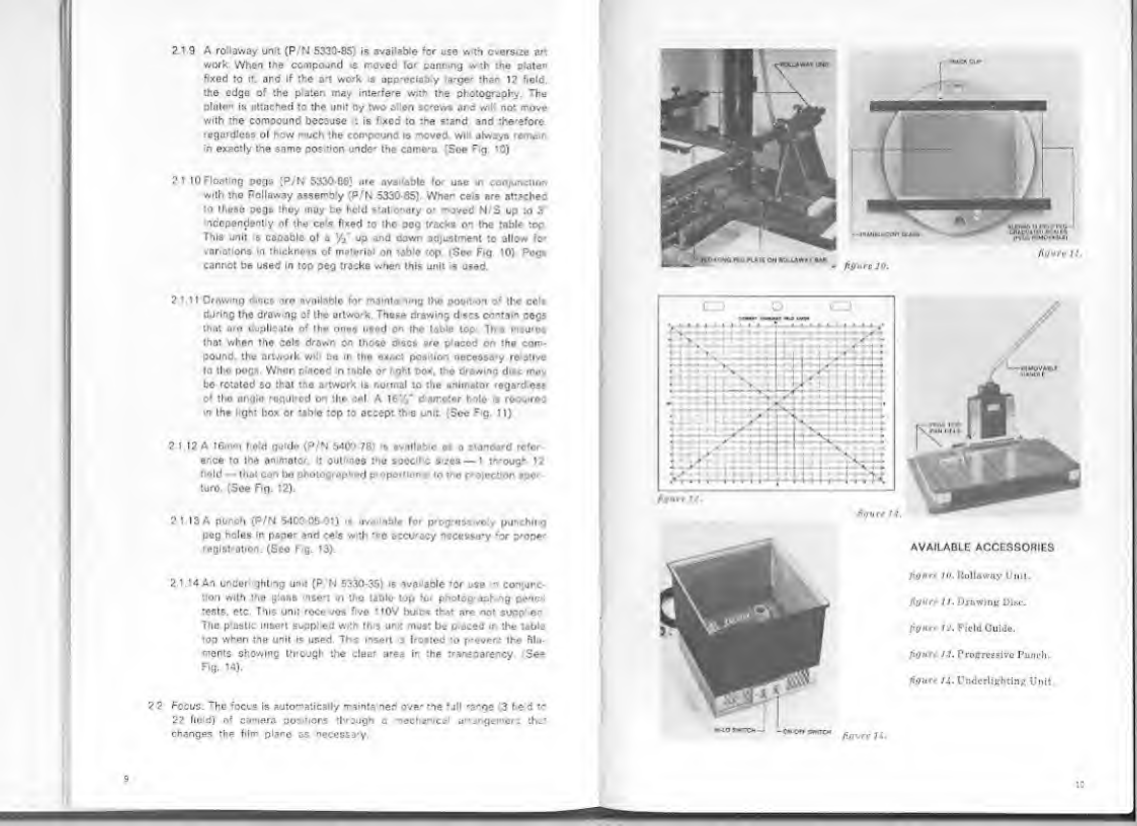
A
ro
'away
unit
(P
N
5320-85)
is
available
for
use
w
m
oversize
art
work
When
tne
compour.d
s
moved
for
panning
.%
th
rhe
plate''
fixed
to
it.
and
if
the
a*t
work
s
app-eciaby
arge-
than
12
field,
the
edge
of
the
p
aten
may
interfe'e
w.m
the
photography
The
pinion
is
attached
to
the
unit
by
two
alien
screws
and
w
not
move
with
the
compound
because
is
fxed
to
the
stand,
and
therefore
regardless
ol
hew
much
the
compound
is
moved
vvi
always
re
nam
in
exactly
tne
same
cos
tion
unde'
the
camera
(See
Fig
10)
2
1
10
Floating
pegs
(P/N
5330-66)
are
nva
able
for
use
n
conjunction
with
the
Rollaway
assembly
(P/N
5330-85)
Whe-
ce
s
are
attached
to
theao
pegs
thoy
muy
be
held
s:al
onary
O'
moved
N
S
up
to
3
ndopondent
y
of
the
cels
fixed
to
the
peg
tracks
on
the
table
top
This
unit
>s
capable
ol
a
/{
up
and
down
adjustment
to
allow
for
variations
In
thickness
of
material
on
table
top
(See
Fig
10)
Po«r
cannot
be
used
in
tep
peg
tracks
when
this
unit
is
used.
2
Ml
Drawing
dmes
nro
ovoitablo
for
mainta
nlng
tho
posit
on
of
the
cols
during
the
draw
ng
of
the
artwork.
These
drawing
d
scs
contain
pegs
that
are
dupllcoto
of
the
ones
used
on
the
table
top
Th»*
Inoun
that
when
the
cols
drawn
on
those
discs
are
placed
on
the
com¬
pound.
the
artwork
wi
bo
in
the
exact
position
necessary
re
stive
to
the
pegs.
When
placed
m
table
o'
l>ght
box.
the
drawing
disc
may
bo
rotated
so
that
tho
atwork
is
normal
to
the
animator
regard
ess
of
tho
angle
rogui'od
on
the
cel.
A
16
!
V
d
amoter
holo
•»
rocu<rcd
in
the
light
box
or
tabio
top
to
occep:
th
o
unit.
(See
F
g.
11)
2
1
12
A
16mm
held
guide
(P/N
5400-78)
is
avallabio
as
o
standard
refer
ence
to
the
animator.
It
outl
n©s
tho
specific
s
.*cs
—
1
tr.-ough
12
f
old
—
that
can
bo
photographed
proportional
to
tho
protection
apor
turo
(See
Fig.
12).
2
1
13
A
punch
(P/N
5400
05-01)
it
available
for
progressively
pui
Ml
g
peg
holes
in
paper
and
cels
with
the
occu-acy
necessa-y
for
p-ope-
registration.
(Seo
F>g.
13).
2
.1.K
An
unseri
ghl
ng
unit
(P
N
5330-35)
is
ava<
able
for
use
n
conjunc¬
tion
with
tho
gass
nse*t
in
tho
tabio
top
for
photog-aph
ng
penc
tests,
etc
This
unit
rocc
vos
five
110V
bu
bs
that
are
not
supp
ec
The
plastic
insert
supp.'
ed
with
this
un.t
must
be
p
aced
in
the
table
top
when
the
unit
is
used
Th
s
insert
s
frosted
to
p-evcr.t
the
fila¬
ments
Showing
th'Ough
the
clear
a*ea
in
the
transparency
'See
Fig.
14).
2
2
Fccus.
T
he
focus
is
automatically
rrainta
ned
ove'
me
*jll
'3'ge
'3
I
e
d
to
22
held)
of
camera
oostiors
through
a
lecharical
urrangemert
that
changes
the
filr
plane
os
neccssa-y.
figure
ti.
AVAILABLE
ACCESSORIES
l'<jnr<
/o.
Rollaway
Unit.
figure
II.
Druwiny
Disc.
fi{/ur<
I*.
Field
Guide.
figure
Progressive
Punch.
figure
U.
Undcrliehting
Unit.
to
9

b)
1
16
second
exposure-mu:
pie
frames
autorrarica
y:
Se:
advance
selector
(Item
9)
at
"Fwd."
(Forward)
or
’
■
Rev."
(Reverse)
and.
only
when
ready
to
proceed
with
the
photography,
set
the
mode
se
ecto-
(Itom
3)
at
“Corn
"
(Contlruous).
c)
Less
than
1/6
second
exposure
—
one
frame
Set
controls
as
in
“a”
and
turn
knob
controlling
tne
auxl
ary
shutter
(See
F
g.
6)
urt
pointer
ponts
at
desired
opening
on
degrees
scale.
_ock
au*
ary
shutter
in
place
by
rotating
knob
(See
Fig
6)
clockwise
unt
snug
d)
Less
than
1
6
second
cxoosu'C'—mult
pie
frames
automat
cally
Set
controls
as
In
b".
However,
before
selecting
continuous
node
turn
the
au*
liary
shutter
control
-nob
(See
Fig
6)
until
the
pointer
points
at
tho
desired
opening
on
deg'ees
scale.
Lock
the
auxiliary
ahuttor
in
pluce
by
rotat
ng
knob
(See
Fig
6)
dock/,
so
until
snug
(See
Chart
1.)
HIM
J
MODI
If
IVcion
AtOClf
Mil
l*>CATC*
'?TM
I*
ZOOM
I
WITCH
INTftGIZMO
cron
up
op
down
UPOSC
BUTTON
i
V
H
CAMLPA
ivif.
m
.
81*110
B!
uICIO*
(zoom
con
mou
ZOOM
POWER
SWITCH
>rc
17.
Control
Console
3
*
2
Fades:
Fades
may
bo
made
by
se
actively
using
tho
auxiliary
shutte'
.-.her
exposing
each
frame
When
making
fades
the
node
selector
~ust
bo
set
at
"S
V
"
(Stop
Motion)
and
kept
there
until
the
fade
s
complete.
The
scale
for
the
fade
is
marked
24
and
32.
These
•'igures
represent
the
number
of
frames
that
will
be
incorporated
in
me
fade
when
an
exposure
s
mace
e:
each
cross
lire
on
the
scale
from
open
to
closed
or
vice
verso.
(See
Fig.
18).
a)
?4
frame
fade:
Turn
knob
controlling
aux
>ary
shutter
from
Open”
until
-r
is
on
first
cross
line
(short)
on
the
top
half
of
the
scale.
Press
the
‘Expose"
button,
and
after
the
act
on
Is
com-
p
etec
rotato
indicator
to
the
next
lino
(long).
Prose
"Exposo”
but¬
ter
Continue
ms
p-ocecure
mak
ng
an
exposure
at
each
cross
line
until
Closed"
s
reached.
The
result
will
be
n
fado
out.
If
tho
Indi¬
cator
is
roved
from
"Cosed"
to
Ine
firs:
cross
line
and
so
on
until
Open"
is
ronchod.
tho
result
will
bo
a
fade
in.
b)
48
frame
It
re
If
tho
procedure
outl
nod
in
-i"
s
foi'owod
and
in
addition
or
exposure
is
made
at
a
point
in
botwoon
oach
lino,
tho
result
will
bo
a
-18
frame
fade.
c)
12
frame
fade
i
a
procedure
outlined
m
“a"
is
followed
but
exposures
made
on:,
a!
ttie
long
cross
i-nes.
tho
rosult
will
be
a
1
?
framo
fade.
d)
32
troro
fado:
If
the
procedure
outlined
in
a”
is
followed
but
on
thn
bottom
half
of
the
scale
tho
result
will
be
o
32
framo
fude
e)
64
frame
/ado:
if
tho
procoduro
outlined
m
"a"
la
followed
on
the
bottom
half
of
the
scale
and.
In
addition
an
exposure
is
modo
nt
a
point
ir
botwoon
oach
lino,
tho
rosult
wfl
be
a
64
frame
fado.
f)
f6
trame
fodo.
If
the
procedure
outlinod
m
"a"
Is
followed
on
thu
bottom
holf
of
the
ecole
but
exposures
made
only
at
tho
long
cross
lines,
the
result
w
bo
a
’6
Iramo
fado.
31
3
Dissohros
Dissolves
may
be
made
by
soloctivoly
using
tho
auxiliary
shutte-
when
expos
ng
each
franc.
When
making
a
dissolve,
the
mode
selector
must
be
set
at
"S
M."
and
kept
thoio
until
the
dis¬
solve
is
comp
ete
T
hc
scale
for
tho
di9solvos
Is
morkod
24
and
32
These
figures
represent
the
number
of
frar.es
that
will
be
ircludcd
in
the
dissolve
when
on
exposuro
is
made
at
oach
cross
line.
Bifort
start
ng
a
dissolve,
check
the
'eadng
on
the
frame
counter,
or
set
•hat
counter
at
"O"
os
dosenbod
in
3
2.1
b).
Overlapping
a
fado
In
anc
a
fade
out
wi
not
result
in
a
pleas
ng
dissolve.
See
Chan
1.
NOTE-
If
the
Combinat
on
Console
shown
m
6.0
has
been
supplied.
Mm
4.
-'9
24)
must
be
in
the
ADV/26
position
and
the
Mode
Soli
ctor.
Item
3
F.g.
24.
must
be
in
thc
Stop
Motion"
or
Con-
:
nuous"
cos
t
on
for
the
Ar
ration
Carrera
to
respord
as
described
m
this
section
ii
13

_
*HAMtS
_
FRAMES
figure
in.
Density
variation*
resulting
from
ui«
of
camera
fa<le
an.!
dissolve
scale.
a)
24
f-ome
dissolve.
P
ace
the
advance
select'
(Item
9.
Fig
17)
In
"Fwd."
(forward)
Turn
the
-nob
con’-ol
ng
the
ouxillory
til
utto*
from
open
to
the
first
cross
lire
(abort)
on
the
top
half
of
the
scale
and
p’coo
tho
’
Expose"
button.
Rotate
tho
knob
until
the
mdicato
is
on
tho
noxt
lino
(long)
and
pross
the
"Expose"
button
Continue
this
procoduro
until
"Closed”
io
reached.
Leave
the
shutter
in
the
"Closod"
position
and
placo
tho
advance
selector
n
the
Rev."
(Reverse)
position.
Actlvato
unit
until
the
frame
counter
read.rg
is
tho
oamo
as
tho
ro.idmg
was
whon
tho
dissolve
was
started.
P
aco
tho
odvance
se
ecto'
in
"Fwd".
forward
Rotate
the
ouxillo-y
shutter
from
closed
to
tho
f.rat
cross
line
(short)
next
to
tho
closed
pos<-
t
on.
Lock
tho
shuttor
nnd
press
the
"Expos**"
button
Continue
this
procodure
until
’’Open”
is
reached.
The
result
will
be
a
24
frame
disnolvo.
b)
48
Fromo
DtMOlva:
If
the
procedure
OUtJkWd
n
"a"
is
followod
ond
In
addition
nn
exposuro
3
made
at
u
point
between
each
no
olso,
the
result
will
bo
a
48
frame
dissolve.
c)
12
Frame
Dissolve:
If
tho
procodure
outlined
in
"a"
>s
followed
but
exposures
made
only
at
the
long
cross
lines,
tho
rosu't
v.
be
o
12
framo
dissolve
d)
32
Framo
Dissolve:
If
the
orocedure
outlined
n
"a”
is
followed
but
on
tho
bottom
half
of
the
scale,
the
result
will
be
a
32
frame
dissolve.
e)
64
Frame
Dissolve*
If
tho
procedure
outi
ned
n
“a"
is
followed
but
on
tho
bottom
half
of
the
scale,
and.
In
add
tion.
an
exposure
Is
made
at
a
point
in
between
each
lino
also,
the
resu't
will
bo
a
64
frame
d
ssolve
f)
16
Frnmo
Disolve
If
tho
procedure
outi.nod
in
“a”
is
followed
on
the
bc"om
half
of
the
scale
cut
exposures
mode
only
at
the
long
cross
lines,
the
result
w
If
be
a
16
frame
dissolve.
SPtLD
(SfC0N08)
3
1.4
The
aux
a-y
shutter
scale
marked
in
degrees
is
closest
to
the
con¬
trol
-.rob.
Exposures
of
ess
than
1/6
second
are
made
oy
rotating
tho
knob
to
the
proper
degree
setting
on
tho
scale
and
locking
t
n
place.
(See
Char*.
1).
chart
I.
Speed
rhnn?o*
multinp
from
auxiliary
■
nutter
r
1
o*edown.
3.2
Frame
Counter:
(Horn
6.
F.g.
17)
3
2.1
The
function
of
this
countor
is
to
constantly
denote
the
numbor
of
frames
advanced
to
any
socuonce.
The
action
of
the
counter
la
as
follows:
a)
The
counter
w
charge
its
reading
by
the
number
of
frames
tho
film
advances.
It
will
add
when
tho
film
s
odvanced
forward
ond
subt-act
when
the
film
is
advanced
in
rovorso
b)
The
counter
may
bo
reset
to
"0“
by
piosslng
the
button
(Itom
4.
Fig.
17)
in
and
releasing
If
th
s
s
done
ot
the
nta-t
of
each
sequence,
tho
operator
will
havo
an
indication
through
each
ooquonce
ns
to
how
many
framos
hnvo
boon
advanced
c)
If
t
is
necessary
to
change
the
count
on
the
counter
for
any
reason,
the
D
git
Selecter
(Item
7.
F.g.
17)
is
provided
for
this
purpose
d)
This
counte'
w
only
count
advances
and
not
exposures.
Tho
film
may
be
advanced
without
exposure
and
the
counter
-ending
will
charge
with
each
advance.
327
A
p-edeterm
ning
counter
(P/N
5320-74)
is
available
for
controlling
tho
number
o?
frames
that
w
II
bo
included
in
any
sequence.
When
a
count
is
set
and
that
count
is
reached,
the
unit
will
be
inoperab'e
sign
tying
to
tho
operator
the
end
of
tho
sequence

CAMERA
3.3.
Sizing:
3.3
1
Sizing
is
accomplished
in
the
following
mannor:
a)
Remove
the
projection
larro
fro-n
the
holding
bracket
and
place
it
on
tno
viewer
as
shown
in
Fig.
16.
Place
the
toggle
switch
in
the
"auto"
or
"on"
position.
b)
Press
the
"Viewer"
actuator
(Item
11.
Fig.
17)
mo-en-anly
and
release
When
tho
viewer
is
in
position,
the
indicator
light
(Item
10.
Fig.
17)
will
glow.
c)
Activate
the
zoom
motor:
Place
tho
zoom
power
switch
(Item
13.
Fig.
17)
In
the
"ON"
position.
The
indicator
light
(Item
12.
Fig
17)
will
glow
when
the
switch
is
n
the
"on"
position
d)
Select
speed
of
zoom
motor
Rotate
knob
(Item
14.
F,g.
17)
to
the
IT
dway
position
NOTE:
Experience
v/.th
me
unit
w.
dictate
when
the
zoom
moto'
should
move
faster
O'
s
ower
than
th
s
Ir
general,
for
short
changes
of
camera
position
s
owo-
speed*
should
bo
u»od
and
for
long
changes
of
camera
postior
the
taste-
speeds
a-e
more
deair
able.
e)
Energize
the
zoom
motor:
Push
the
energizing
switch
(Item
15.
Fig.
17)
either
up
or
down
for
the
camo-a
direction
noedod
and
hold
tho
switch
until
tho
camo-n
position
la
correct
as
ndicoted
by
the
projocted
reticle.
The
reticle
s
marked
with
three
rectang’es
The
smallest
rectangle
ie
dotted
ond
allows
for
n
25%
cutoff
for
T.V.
Tho
next
larger
rectangle
Ind
cates
tho
area
that
will
be
pro.ected
on
th*
ocroon
Tho
largest
rcctonglu
indicates
tho
area
that
will
be
oxpoaod
on
tho
film.
(Sco
Fig
19)
19.
Reticle
Maritime*
Note:
Outer
rectangle
shows
th.r
nren
of
the
film
that
will
be
exposed.
This
i.s
larger
than
the
area
of
the
film
that
will
be
projected
on
the
screen,
to
keep
dost
ar.d
lint
that
may
collect
in
the
aperture
from
marring
the
projected
Image.
0
Deactivate
the
zoom
circu
ts:
Place
tr.e
zoom
power
switch
(Horn
13.
Fic
17)
in
the
“OFF"
position
This
precaution
will
avoid
the
possib
lily
of
the
camera
be
ng
accidentally
moved
during
the
photography.
g)
Return
the
viewer
to
its
normal
position:
Press
tho
"viewer"
actuator
(item
11.
F.g.
17)
momentarily
and
release
f
the
toggle
switch
controlling
tho
projection
bmp
was
placed
>n
the
"ON"
poni
lion,
place
it
:
n
the
"OFF"
position.
h)
Sequel
el
change
of
sizirg.
Place
self-adhering
tape
on
the
un-
marked
positioning
scale
and
mark
the
tape
at
tho
necessary
inter¬
vals
for
each
exposu-e.
The
camera
is
then
roved
to
the
successive
markings
on
the
tape
after
each
exposure
34
Zooms.
This
unit
prov
des
tie
use-
with
tho
ability
to
make
either
a
stop
motion
zoom
or
a
continuous
zoom
3.4
1
A
stop
motion
zoom
<a
made
n
the
followirq
mannoi
a)
P
lace
self-acher
ng
tape
on
the
unmarked
scale.
Mark
tho
tape
at
the
beginning
of
the
zoom
nr:!
the
ond
of
tho
zoom
M.irk
in
between
in
such
o
manner
that
tho
cpacirg
between
tho
frames
in
:•
o
beginr
rg
d
..:
tho
end
of
U
e
zoom
Is
lost!
than
in
tho
middle
of
the
zoom
When
sequential
f-.imos
am
exposori
nt
each
murk,
th
a
p'oeedure
will
result
in
a
zoom
that
w
l
have
o
s
ow
start
and
a
alow
stop
ond
give
a
phasing
effect
on
tho
acroon,
34
2
A
continuous
zoom
i*
made
n
the
fo
owing
manner
a)
After
positioning
me
comera
for
tho
start
of
the
zoom
as
de¬
scribed
ir
(urn
the
rheoatat
(Itam
14
Fig
17)
ua
for
ou
it
wll
go
counterclockwise
ond
mark
the
scab
for
the
erd
of
the
zoom
b)
A
dry
-un
is
mado
I
-st
to
check
the
speed
at
which
thu
zoom
should
be
made
fo-
the
number
of
fiomou
to
be
incorporated.
c)
Turn
the
rheoatat
(llem
14.
Fig.
17)
os
for
counterclockwise
as
it
wil
go.
close
the
auxiliary
shutter,
mark
down
tho
frame
counter
reading
and
tho
zoom
counter
reading.
d)
Place
tho
mode
selector
in
continuous
und
turn
tho
rheostat
s
owly
clockwise,
ncreosing
the
-ate
of
turning
until
the
max
mum
doaired
cpcod
is
reached.
As
the
ond
of
tho
zoom
is
noarod.
turn
•-e
rheostat
counterclockw.se
slowing
an
it
approaches
the
end
o‘
tho
scale
c)
Check
tho
frame
counter
-enc
ng
against
the
or
ginol
reading
to
dele-mine
if
the
number
of
frames
s
correct.
NOTE.
It
may
bo
de-
a
rable
to
try
th
o
v.
thou!
f.lm
a
few
Simon
tho
Tirol
bmo
thin
typo
of
zoom
:s
attempted
n
o'der
to
get
a
"feel"
of
the
contro.
t
should
ce
borne
in
r
nd
that
deterioration
occurs
in
the
sprocket
holes
each
t
me
they
are
transported
and
because
of
this
"he
f
’m
should
be
transported
as
little
as
possible.
0
Return
the
f
n
and
the
camera
position
to
the
original
read
ngs
Open
the
oux
liar/
shutter
and
proceed
as
delated
in
(d).
g)
This
typo
of
zoom
when
done
correctly
will
approximate
exactly
the
required
zoom,
e.,
if
a
sixty
frame
zoom
is
wanted
ths
may
result
in
a
58
or
64
frame
zoom
If
*
s
imperative
that
the
zoom
start
and
stop
at
exactly
the
p-oper
fe!d
and
exact
y
t-.e
numbo-
of
framos.
then
the
stop
me: on
techniques
should
be
used
34
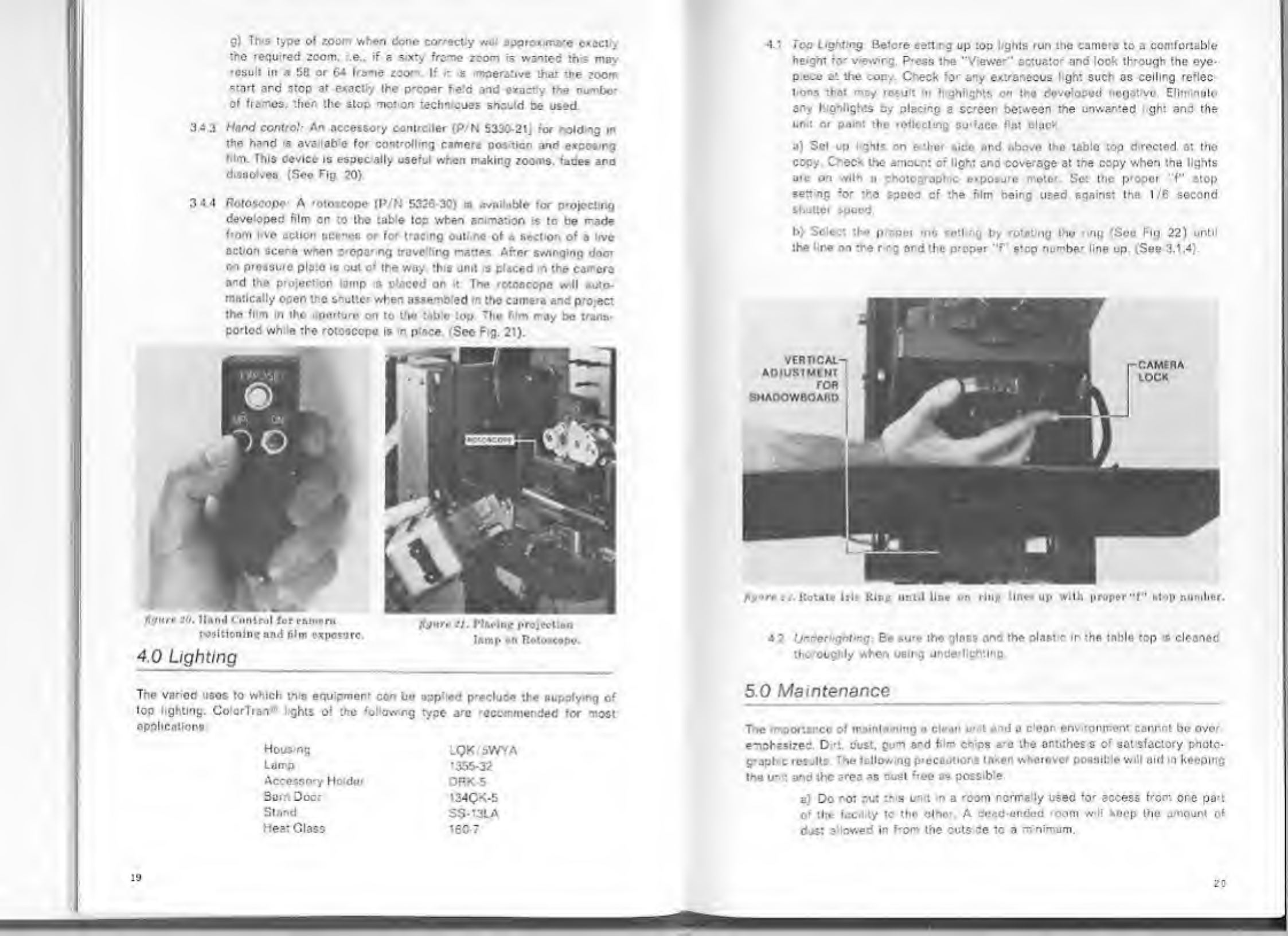
3
Hand
control:
An
accessory
controller
(P/N
5330-21)
for
nofdmg
in
the
hand
s
availab'e
for
controlling
camera
position
and
exposing
Mm.
This
device
is
espec.ally
useful
when
making
zooms,
fades
and
disoolvos
(Soe
Fig
20)
34
4
Roroscope
A
-otoscope
(P/N
5326
30)
is
available
for
projecting
developed
film
on
to
the
table
top
when
an
.matron
is
to
be
made
from
l.ve
action
scenes
or
for
tracing
oull.ne
of
a
sect
on
of
a
live
action
scene
when
crepa-
ng
trave
ling
mattes
After
swinging
door
on
pressure
plate
is
out
o
;
the
way.
this
unit
s
p^ced
m
the
camera
and
tho
projection
lamp
o
placod
on
it
The
rotoscopo
will
auto¬
matically
open
tho
Shutter
when
assemb'ed
n
tho
camera
and
project
tho
Mm
in
tho
oporturo
on
to
tho
table
top
The
Mm
may
bo
trans¬
ported
wh
a
the
rotoscopo
Is
n
p'ace
(See
Fig.
2’).
figure
itO.
Hand
Control
for
emnrm
positioning
and
film
exposure.
4.0
Lighting
The
varied
usos
to
which
this
eguipmer-
con
bo
upped
p-ecludo
the
supplying
of
lop
lighting.
CoiorTran*
lights
of
tho
following
type
j-c
recomended
for
most
applications
Hous
ng
LQK
5WVA
Lamp
1355-32
Accessory
Holdor
DRK
5
Bam
Doer
134QK-5
Stand
SS-13LA
Heat
Glass
160-7
10
•I
t
Too
Lighting
Before
sett
rg
up
top
l.ghts
run
the
camera
to
a
comfortable
height
for
viewirg
Press
tie
"Viewer"’
actuator
and
look
through
the
eye-
pece
at
the
cop..
C-eck
'0'
any
extraneous
light
such,
as
ceiling
reflec
tions
that
may
result
m
highlights
on
the
developed
negative.
Eli-"
mile
ary
highlights
by
placing
a
screen
between
the
unwanted
gh;
ana
the
unit
or
pain:
the
reflecting
surface
flat
black
a)
Sot
up
ghts
on
e
:hor
side
and
above
tho
toblo
top
directed
at
tho
copy.
Check
the
amount
o'
light
and
coverage
at
the
copy
when
tne
lights
arc
on
with
n
photographic
expot
are
meter
Set
the
proper
f"
stop
for
the
speed
of
the
film
being
used
against
lie
1/6
second
shatter
speed.
b)
Sol.
•
tf
«•
p
per
ins
eti
;
by
rot.it
ng
tho
mg
[Soe
Fig
22)
until
the
re
on
the
r
ng
and
the
proper
"f
stop
numbe-
line up.
(See
3.1.4).
figure
..
.
Rotate
lrl>
Kirz
until
line
on
rinjc
linn
up
with
proper"f"
stop
number.
4
2
Underl/gbting:
Be
su-c
the
gloss
©no
the
piast
In
the
table
top
is
cleanod
tho-oughly
when
using
underlightlng
5
0
Maintenance
_
_
_
Tne
importance
of
maintn
ning
a
cloon
u-
t
and
o
clean
env
-oniren:
cannot
be
ovor
emphasizes
D
-t.
dust.
gu*n
a-d
film
chips
«:-c
the
antithes
s
of
satsfactory
pholo-
g-jpl
c
results.
Tne
following
precajtiors
token
wherover
possible
will
aid
in
keeping
the
un:
and
the
area
as
cusl
*'rcc
as
possible
a‘;
Do
ro:
out
tr
s
unit
in
a
room
rcrn-ally
used
'or
access
from
ore
pa*t
of
the
facility
to
the
other.
A
dead-ended
roam
will
hoop
tho
amount
of
djst
a
owed
in
f-om
the
cuts
de
*0
a
minimum.

b'
A
slightly
higher
pressure
nor’.aired
in
the
-oon
housing
the
unit
will
keep
dust
from
enter
ng
from
other
areas
A
dou=!e
errrarcc
ead-i-
will
also
be
of
help
C)
If
clear
ng
5
done
by
vacuum
only
and
rot
by
sweep
ng.
ard
f
the
vacuum
exhaust
*s
located
outside
of
the
,
03
m.
dost
will
also
be
kepi
to
a
minimum
d)
If
the
room
is
swept,
the
floor
should
he
damoenea
to
keep
the
due:
from
swirling.
0
)
A
dust
cover
shou
d
be
draped
ever
the
camera
and
lens
when
the
un
t
is
not
in
use
f)
The
Ions
should
oe
cleaner
orce
a
wee*
o'
eacn
time
it
15
nse-teo
with
lens
tissue
or
silicon-improsnated
paper
("Sigh!
Savers
.
sold
m
optical
anc
drugstores).
g)
The
gloss
insert
should
be
clesr.ee
thoroughly
each
1
me
befo-e
in¬
sertion
h)
Tho
camern
should
be
brurnod
out
thoroughly
oach
time
be'o'e
load
Ing
film
Special
attention
shou'd
bo
given
to
tho
film
path
and
aperture
I)
Tho
sprocket
guides
and
pressure
ploto
should
bo
doored
every
thrty
days
w
th
a
cleanor
eguivalor-
to
Trichloroethylene
j)
It
*&
also
des
'able
to
refra-n
from
smoking
in
tho
a*en
conta
nmg
this
unit
Tho
residue
in
tho
smoke
w,ll
c
ng
to
all
tho
glass
su-foces
and
the
lens
cauoing
n
deterioration
ir
the
quolty
of
tho
photofl'.mhy
•
......
!
•
mli
nuiion
Tontrol
Panel.
figure
?J.
Model
M27.ni
Filmstrip
Slide
Camera.
6.0
Interchangeability
of
Camera
Ir
odd
t
on
to
the
animation
csr-e-a
supc
ed
with
-h
s
1
-
t
(5326-01).
the
u't
cm
be
equipped
at
the
factory
to
also
receive
:ne
5327-01
F
mstnp
Slide
Camera.
When
this
option
the
folio-wing
instructicr8
apply
and
the
control
panel
shown
in
Fig.
24
is
provided
6.1
Corrects
Bch
nd
the
eyepiece
s
n
moin'
mask.
If
tho
oyop
oce
is
-ernovod.
this
mask
with
ts
lens
can
00
s
ipped
out
of
tho
unit.
Whon
tho
oyopioce
IB
put
beck
and
tho
5320-52.
28mm
lono
roplncod
with
th
5320-50.
55mm
ens.
it
w
be
pocs
ole
to
see
three
rocumglos
in
oddi
tion
to
tho
throo
rectangles
previously
soon
Tho
additions
nt
•>
..
ngs
are
for
use
w
th
the
5327-01
camera
6.2
Retch
All
throe
ol
the
new
rectanglos
u*e
lorgor
than
the
rectar.gliiH
used
for
16mm
photography
w.lh
the
5326-01
camoro
Tho
lorgost
roctanglo
do
ncates
-he
area
that
w
be
exposed
on
the
35mm
film
fo'
double
frame
(e
do)
ohotugiuchy
and
••
the
some
hUc
as
tho
aporture
m
tho
camera
The
area
between
the
largest
rectengle
and
the
next
larger
delineates
the
po'tton
that
will
be
masked
by
tho
Eastman
Kodak
mount.
Tho
thlid
rectangle
from
tho
outsido
delineates
tho
area
of
the
copy
that
will
be
incorporated
in
a
single
frame
exposure
.
6.3
The
5326-01
Cumeiv
•
NVSd
from
the
Stand
os
described
in
1.1.1
and
n
ilaoed
W
-
the
5327-01
Camera
The
instruction
Manual
for
tho
5333-03
Filmstr
p/Shde
Stare
provides
tho
neceooary
operating
instructions
for
using
t‘-o
5327-01
camera
and
its
controls
64
Provision
for
Filmstr
.
S
to
Gamer*;
If
it
is
desi-able
to
purchase
only
the
animat
i
came
-
if
daily
/-•
■
.(
provision
for
adding
the
Filmstrip/Slide
Camera
in
the
future,
this
may
bo
done
by
ordering
P/N
5320-71
However.
P
N
5320-50.
the
SSmm
le-s.
a'd
P
K
5330-12
&
'3.
the
focusing
cam
for
the
55nm
lens,
should
bo
pure-used
with
tho
initial
ordor.
Stands
wi
rc-
qu>e
return
to
the
factory-
to
have
film
planes
matched.
?\
22
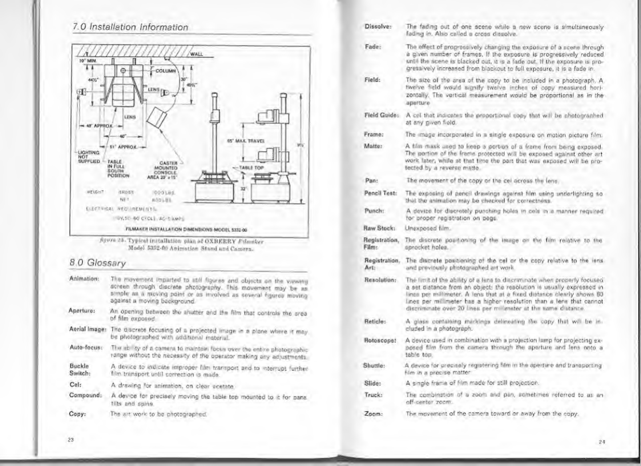
7.0
Installation
Information
Modal
5332-00
Animation
Stand
and
Camera.
8
0
Glossary
Animation:
Th«
movement
mpartod
to
still
figures
and
obK-ts
on
the
viewing
scroen
through
discrete
photography
This
movement
may
be
at
I
mi
.
i
-|
point
or
as
involved
as
aoverol
figures
moving
ogamst
a
moving
background
Aperturo:
An
opening
between
tho
shutter
and
the
film
that
controls
the
area
of
film
exposed
Aerial
Image:
The
discrete
focusing
of
a
projected
image
in
e
plane
where
d
may
bo
photographed
w.th
additional
material.
Auto-focus:
Tho
obility
of
a
Comoro
to
maintain
focus
over
tho
entire
photographic
range
without
the
necess
ty
of
the
operator
r-akirg
any
adjustments.
Buckle
A
device
to
Indicate
improper
film
trarspor:
and
to
njer'upt
‘ur.her
Switch:
film
transport
until
correct
on
is
made
Cel:
A
drawing
‘or
animation,
on
clear
acetate
Compound:
A
dev
ce
for
precisely
moving
the
table
top
mounted
to
:
fo*
pans
tilts
and
6pins.
Copy:
The
art
wo'k
to
be
photog'ophed.
23
Dissolve:
The
fad
ng
out
of
one
scene
while
a
new
scene
is
simultaneously
fading
in
Also
ca
ed
a
cross
d
ssolve.
Fade:
The
effect
of
prog-essively
changing
the
exposure
of
n
scone
through
a
given
numae'
o‘
f'ames.
If
the
exposu-e
is
progressively
reduced
unt-l
the
scene
Is
blacked
out.
it
r.
a
fade
out.
If
the
oxponuro
ia
pro¬
gressive
y
increased
from,
blackout
to
full
exposure,
t
is
a
fade
in.
Field:
The
size
ol
the
area
of
the
copy
to
oe
included
in
a
photograph.
A
twe
vc
‘eld
would
signify
two
vo
inches
of
copy
measured
hori¬
zontally.
The
vert
cal
measurement
would
be
proportional
as
in
the
aperture
Field
Guide:
A
ccl
that
Ind
cates
tho
proportional
copy
that
wll
bo
photographer!
at
any
given
field.
Frame:
Ihe
image
incorpo'aled
in
a
single
exposure
on
motion
picture
film.
Matte:
A
l.lm
mask
used
to
keop
a
port
on
of
a
frame
from
being
exposed.
Tlir
portion
of
the
frame
protected
w
II
bo
exposed
against
other
art
work
later,
while
at
that
t
mo
the
port
that
was
exposed
will
be
pro¬
tected
by
a
reverse
marto.
Pan:
The
movement
of
tho
copy
or
the
col
across
the
lens.
Pencil
Test:
The
exposing
of
pcnc
drawings
ngs
rsi
film
using
unde'llghtlng
so
that
the
animation
may
bo
checked
lor
correctness
Punch:
A
device
foi
d«ocrotoly
punching
holon
in
cola
n
a
manner
roqwrml
for
propor
reg
station
on
pegs
Raw
Stock:
Unexposed
film
Registration.
Tho
ducroto
positioning
of
tho
Imago
on
the
film
rolatlvo
to
tho
Film:
sprocket
holes.
Registration,
The
discrete
pos
t
oning
of
the
cel
or
the
copy
relative
to
the
ens
Art:
end
previously
photographed
art
work
Resolution:
The
m
t
ol
tho
ability
of
a
lens
to
discriminate
whon
properly
focusod
a
set
d
stance
from
an
object:
the
resolut
on
is
usually
expressed
In
ncs
pe-
mil!
motor
A
ons
that
at
o
fixed
dict.mco
clearly
chows
80
I
res
per
mi
mete'
has
a
hiphe'
resolut
on
than
a
lens
that
cannot
discriminate
over
20
I
non
par
r
imeter
nt
the
same
d
stance
Reticlo:
A
glass
containing
markings
delineating
tlm
copy
that
will
be
In¬
cluded
in
a
photograph.
Rotoscope!
A
cevice
used
n
comb
mat
on
with
a
project
on
lamp
for
projecting
ex¬
posed
film
from
the
camera
through
iho
aperture
and
Ions
onto
o
table
top.
Shuttle:
A
device
‘or
procisely
registering
film
n
the
aperture
ond
transporting
him
in
a
proc
so
matte'
Slide:
A
s
ngle
frame
of
f
lm
made
for
still
projection.
Truck:
The
combination
of
a
zoom
and
pan,
sometimes
referred
to
as
an
off-center
zocm.
Zoom:
The
movement
of
the
came'a
tewa'd
or
away
Mom
the
copy
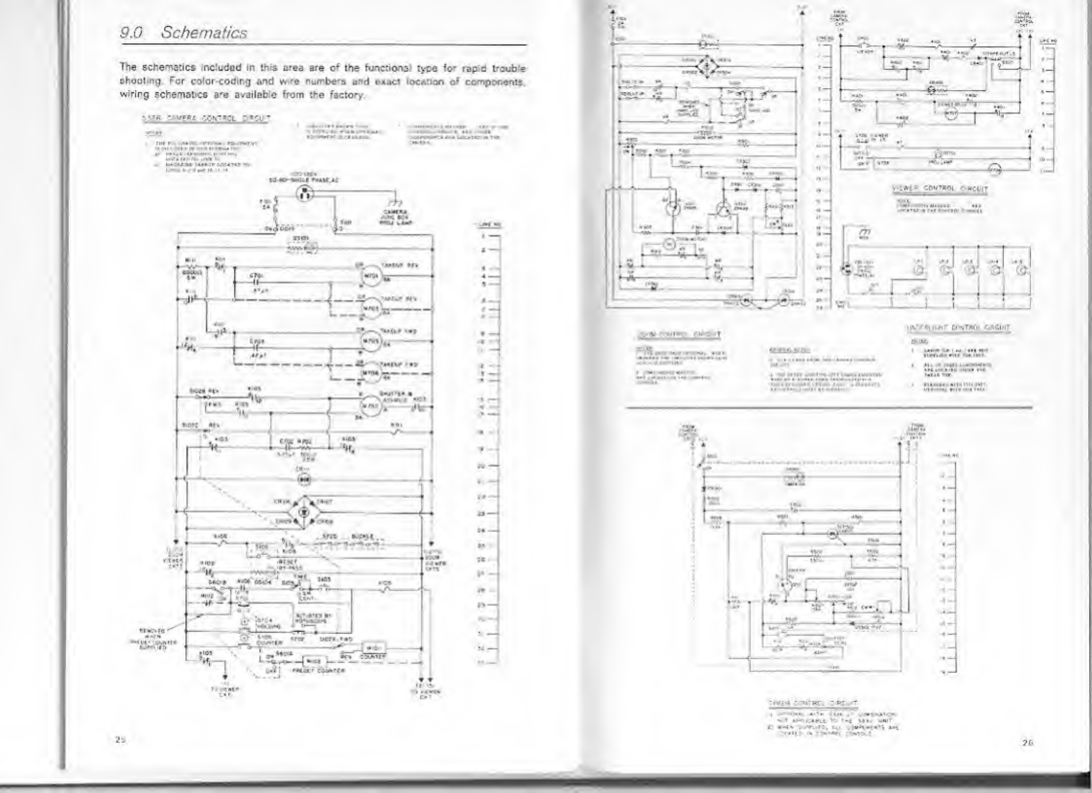
9.G
Schematics
The
schematics
included
in
this
area
are
o
;
the
functional
type
fo-
rap
d
t-cub
a
shooting.
For
color-coding
and
w.'e
numbe-s
and
exact
location
of
components,
wiring
schematics
a-e
availab’c
from
the
factor/.
.
i*t«
cotreoi
circuit
•
...
J
-

Si‘i|
•
*
;•/
..vfMACON
*>'
a
iTri
53W
CAMDU
r*
f**AC€>

OXBERRY


