manuals.online logo
Brands
  1. Home
  2. •
  3. Brands
  4. •
  5. Monacor
  6. •
  7. Digital Camera
  8. •
  9. Monacor TVCCD-119 User manual

Monacor TVCCD-119 User manual

12V
Video
1
S/W-Türspionkamera
Bitte lesen Sie diese Anleitung vor der Installation
gründlich durch und heben Sie sie für ein späteres
Nachlesen auf.
1 Einsatzmöglichkeiten
Die Schwarzweißkamera mit einem extremen Weit-
winkelobjektiv ist für den Einsatz als Türspion in
Videoüberwachungsanlagen (CCTV) konzipiert. Sie
kann in Türen mit einer Stärke von 42 mm bis 66 mm
eingebaut werden. Die Kamera verfügt über einen
automatischen elektronischen Shutter und eine auto-
matische Verstärkungsregelung (AGC).
2 Hinweise für den sicheren Gebrauch
Die Kamera entspricht allen relevanten Richtlinien der
EU und ist deshalb mit gekennzeichnet.
GSchützen Sie die Kamera vor Tropf- und Spritzwas-
ser, hoher Luftfeuchtigkeit und extremen Temperatu-
ren (zulässiger Einsatztemperaturbereich 0 – 40 °C).
GBerühren Sie die Objektivlinsen nicht mit den Fin-
gern und verwenden Sie für ihre Reinigung nur Mit-
tel speziell für optische Linsen.
GWird die Kamera zweckentfremdet, nicht richtig mon-
tiert, falsch angeschlossen oder nicht fachgerecht
repariert, kann keine Haftung für daraus resultieren-
de Sach- oder Personenschäden und keine Garantie
für die Kamera übernommen werden.
3 Inbetriebnahme
1) Ein Loch mit einem Durchmesser von 21 mm in die
Tür bohren. Zusätzlich eine Aussparung für die
Verlegung des Kabels fräsen.
2) Die Kamera, z. B. wie in der Abbildung gezeigt, an
der Tür montieren. Dabei die Montagehülse (4)
über die Kamera (6) schrauben, so dass die Tür (5)
dazwischen klemmt. Das Kabel in die seitliche Nut
des Flansches der Montagehülse legen. Die Mon-
tagehülse erst nach einem Testbetrieb mit der Tür
verschrauben.
3) Das Videosignal am BNC-Stecker (2) über ein ab-
geschirmtes Kabel auf den Videoeingang eines
Monitors geben. Bei einer Kabellänge über 100 m
sollte ein Videoverstärker zwischen Kamera und
Kabel geschaltet werden, um die Kabelverluste aus-
zugleichen.
4) An die Kleinspannungskupplung (1) ein stabilisier-
tes 12-V-Netzgerät mit einer Belastbarkeit von
mindestens 110 mA anschließen (z. B. PSS-600E
von MONACOR). Es wird ein Kleinspannungsste-
cker 5,5/2,1 mm (Außen-/Innendurchmesser) be-
nötigt. Unbedingt auf die richtige Polung achten:
Soll die Kamera endgültig aus dem Betrieb
genommen werden, übergeben Sie sie zur
umweltfreundlichen Entsorgung einem ört-
lichen Recyclingbetrieb.
Den Pluspol an den Mittelkontakt des Steckers
anlegen.
5) Nach dem Anlegen der Betriebsspannung den
Monitor einschalten und die Kamera so drehen,
dass das Bild richtig herum auf dem Monitor
erscheint. Erst jetzt die Montagehülse (4) an der
Tür festschrauben. Die Abdeckkappe (3) auf den
Flansch der Montagehülse schrauben; dabei
darauf achten, dass das Kabel in der seitlichen Nut
des Flansches liegt.
4 Technische Daten
Bildaufnehmer: . . . . . . . CCD-Chip, 8,5 mm (1/3″)
Video-System: . . . . . . . . CCIR, hor. 15 625 Hz,
vert. 50 Hz
Anzahl der Bildpunkte: . hor. 500 × vert. 582
Auflösung: . . . . . . . . . . . 400 Linien
Objektiv: . . . . . . . . . . . . 1 : 1,2/1,78 mm
Shutter: . . . . . . . . . . . . . 1/50 s bis 1/100 000 s
Mindestbeleuchtung: . . . 0,01 Lux
Gamma-Korrekturfaktor: 0,45
Signal/Rausch-Abstand: > 45 dB
Videoausgang: . . . . . . . 1 Vss/75 Ω
Einsatztemperatur: . . . . 0 – 40 °C
Stromversorgung: . . . . . 12 V /110 mA
Änderungen vorbehalten.
TVCCD-119 Best.-Nr. 19.0280
B/W Spyhole Camera
Please read these operating instructions carefully
prior to the installation and keep them for later use.
1 Applications
The black-and-white camera with an extra wide angle
lens is designed for use as a spyhole camera in video
surveillance systems (CCTV). It can be installed in
doors of a thickness from 42 mm to 66 mm. The cam-
era has an automatic electronic shutter and an auto-
matic gain control (AGC).
2 Safety Notes
The camera corresponds to all relevant directives of the
EU and is therefore marked with .
GProtect the camera against dripping water and
splash water, high air humidity, and extreme tem-
peratures (admissible ambient temperature range
0 – 40 °C).
GDo not touch the lenses of the lens assembly with
your fingers and only use specific cleaning agents
for optical lenses for cleaning.
GNo guarantee claims for the camera and no liability
for any resulting personal damage or material dam-
age will be accepted if the camera is used for other
purposes than originally intended, if it is not correct-
ly mounted, connected, or not repaired in an expert
way.
3 Operation
1) Drill a hole with a diameter of 21 mm into the door.
In addition, mill a cutout for laying the cable.
2) Mount the camera to the door, as shown in the fig-
ure. Screw the mounting sleeve (4) over the cam-
era (6) so that the door (5) is clamped inbetween.
Lay the cable in the lateral groove of the mounting
sleeve flange. Perform a test operation before
screwing the mounting sleeve to the door.
3) Feed the video signal at the BNC plug (2) via a
screened cable to the video input of a monitor. With
a cable length of more than 100 m, it is recom-
mended to insert a video amplifier between the
camera and the cable to compensate cable loss.
4) Connect a regulated 12 V power supply unit with a
power rating of at least 110 mA (e. g. PSS-600E
from MONACOR) to the low-voltage inline jack (1).
A low voltage plug 5.5/2.1 mm (outside/inside
diameter) is required. Observe in any case the cor-
rect polarity: Place the positive pole at the centre
contact of the plug.
5) After applying the operating voltage, switch on the
monitor and turn the camera so that the picture
If the camera is to be put out of operation
definitively, take it to a local recycling plant
for a disposal which is not harmful to the
environment.
appears on the monitor in the correct way before
screwing the mounting sleeve (4) to the door.
Screw the cover (3) on the mounting sleeve flange;
pay attention that the cable is placed in the lateral
groove of the flange.
4 Specifications
Image sensor: . . . . . . . . 8.5 mm (1/3″) CCD chip
Video system: . . . . . . . . CCIR, hor. 15 625 Hz,
vert. 50 Hz
Number of pixels: . . . . . hor. 500 × vert. 582
Resolution: . . . . . . . . . . 400 lines
Lens: . . . . . . . . . . . . . . . 1 : 1.2/1.78 mm
Shutter: . . . . . . . . . . . . . 1/50 s bis 1/100 000 s
Minimum illumination: . . 0.01 lux
Gamma correction
factor: . . . . . . . . . . . . . . 0.45
S/N ratio: . . . . . . . . . . . . > 45 dB
Video output: . . . . . . . . . 1 Vpp/75 Ω
Ambient temperature: . . 0 – 40 °C
Power supply: . . . . . . . . 12 V /110 mA
Subject to technical modification.
D A CH
GB
3
4
5
min. 42 mm
max. 66 mm
6
2
®
MONACOR INTERNATIONAL GmbH & Co. KG • Zum Falsch 36 • 28307 Bremen • Germany
Copyright©by MONACOR INTERNATIONAL. All rights reserved. A-0380.99.02.06.2012
®
ment montée, branchée ou nʼest pas réparée par
une personne habilitée, de même, la garantie
deviendrait caduque.
3 Fonctionnement
1) Percez un trou dʼun diamètre de 21 mm dans la
porte. Découpez en plus une encoche pour le pas-
sage du câble.
2) Montez la caméra à la porte comme indiqué sur le
schéma par exemple. Vissez la douille de montage
(4) au-dessus de la caméra (6) de telle sorte que la
porte (5) soit prise entre. Passez le câble dans la
rainure latérale de lʼembout de la douille de monta-
ge. Ne vissez la douille de montage quʼune fois que
vous avez testé le fonctionnement avec la porte.
3) Appliquez le signal vidéo présent à la fiche BNC
(2) via un câble blindé à lʼentrée vidéo dʼun moni-
teur. Pour une longueur de câble supérieure à
100 m, il est recommandé dʼinstaller un amplifica-
teur vidéo entre la caméra et le câble pour com-
penser les pertes en ligne.
4) Connectez une alimentation stabilisée 12 V avec
une capacité de charge de 110 mA au moins (p. ex.
PSS-600E de MONACOR) à la fiche alimenta-
tion (1). Une fiche basse tension 5,5/2,1 mm (dia-
Lorsque la caméra est définitivement retirée
du service, vous devez la déposer dans une
usine de recyclage de proximité pour contri-
buer à son élimination non polluante.
mètre extérieur/diamètre intérieur) est nécessaire.
Veillez à respecter impérativement la polarité :
mettez le pôle plus au contact médian de la fiche.
5) Une fois la tension de fonctionnement appliquée,
allumez le moniteur et orientez la caméra de telle
sorte que lʼimage apparaisse sur le moniteur de
manière correcte. Vissez ensuite la douille de
montage (4) sur la porte. Vissez le cache (3) sur
lʼembout de la douille de montage : veillez à ce que
le câble passe dans la rainure latérale de lʼembout.
4 Caractéristiques techniques
Système : . . . . . . . . . . . puce CCD, 8,5 mm (1/3″)
Système vidéo : . . . . . . CCIR, hor. 15 625 Hz,
vert. 50 Hz
Nombre de points : . . . . hor. 500 × vert. 582
Résolution : . . . . . . . . . . 400 lignes
Objectif : . . . . . . . . . . . . 1 : 1,2/1,78 mm
Obturation : . . . . . . . . . . 1/50 s à 1/100 000 s
Luminosité minimale : . . 0,01 lux
Facteur de correction
gamma : . . . . . . . . . . . . 0,45
Rapport signal/bruit : . . > 45 dB
Sortie vidéo : . . . . . . . . . 1 Vcc/75 Ω
Température fonc. : . . . . 0 – 40 °C
Alimentation : . . . . . . . . 12 V /110 mA
Tout droit de modification réservé.
TVCCD-119 Best.-Nr. 19.0280
Telecamera b/n per spioncino
Vi preghiamo di leggere attentamente le presenti
istruzioni prima dellʼinstallazione e di conservarle per
un uso futuro.
1 Possibilità dʼimpiego
La telecamera b/n è stata realizzata con un obiettivo
grandangolare estremo per lʼimpiego come spioncino
in impianti di sorveglianza video (CCTV). Può essere
montata in porte di spessore fra 42 e 66 mm. Dispone
di un otturatore elettronico automatico e di regolazio-
ne automatica del guadagno (AGC).
2 Avvisi di sicurezza
La telecamera è conforme a tutte le direttive rilevanti
dellʼUE e pertanto porta la sigla .
GProteggere la telecamera dallʼacqua gocciolante e
dagli spruzzi dʼacqua, da alta umidità dellʼaria e da
temperature estreme (temperatura dʼimpiego
ammessa 0 – 40 °C).
GNon toccare le lenti dellʼobiettivo con le dita, e per
pulirle usare solo mezzi per lenti ottiche.
GNel caso dʼuso improprio, di montaggio sorretto, di
collegamenti sbagliati o di riparazione non a regola
dʼarte della telecamera, non si assume nessuna
responsabilità per eventuali danni consequenziali a
persone o a cose e non si assume nessuna garan-
zia per la telecamera.
3 Messa in funzione
1) Applicare nella porta un foro del diametro di 21 mm
e fresare una canalina per la posa del cavo.
2) Montare la telecamera nella porta, come illustrato in
calce alla pagina. Avvitare la boccola di montaggio
(4) sulla telecamera (6) in modo da stringere la
porta (5) in mezzo. Inserire il cavo nella scanalatura
laterale della flangia della boccola. Avvitare la boc-
cola alla porta solo dopo aver testato il funziona-
mento.
3) Portare il segnale video presente al connettore
BNC (2) sullʼingresso video di un monitor serven-
dosi di un cavo schermato. Se il cavo supera i
100 m di lunghezza conviene inserire un amplifica-
tore del segnale video fra telecamera e cavo per
compensare le perdite dovute al cavo.
4) Alla presa per alimentazione DC (1) collegare un
alimentatore 12 V stabilizzato con potenza minima
di 110 mA (p. es. PSS-600E della MONACOR). È
richiesta una spina per alimentazione DC 5,5/
2,1 mm (diametro esterno/interno). Fare assoluta-
mente attenzione alla corretta polarità: collegare il
polo positivo con il contatto centrale della spina.
Se si desidera eliminare la telecamera defi-
nitivamente, consegnarla per lo smaltimento
ad unʼistituzione locale per il riciclaggio.
5) Dopo aver applicato la tensione dʼesercizio, accen-
dere il monitor e girare la telecamera finché lʼim-
magine è riprodotta correttamente sul monitor. A
questo punto avvitare la boccola di montaggio (4)
sulla porta. Avvitare il cappuccio (3) sulla flangia
della boccola e fare attenzione che il cavo rimanga
nella scanalatura laterale della flangia.
4 Dati tecnici
Sensore ottico: . . . . . . . chip CCD, 8,5 mm (1/3″)
Sistema video: . . . . . . . CCIR, orizz. 15 625 Hz,
vert. 50 Hz
Numero pixel: . . . . . . . . orizz. 500 × vert. 582
Risoluzione: . . . . . . . . . 400 linee
Obiettivo: . . . . . . . . . . . . 1 : 1,2/1,78 mm
Shutter: . . . . . . . . . . . . . 1/50 s a 1/100 000 s
Illuminazione minima: . . 0,01 Lux
Fattore di correzione
del gamma: . . . . . . . . . . 0,45
Rapporto S/R: . . . . . . . . > 45 dB
Uscita video: . . . . . . . . . 1 Vpp/75 Ω
Temperatura dʼesercizio: 0 – 40 °C
Alimentazione: . . . . . . . 12 V /110 mA
Con riserva di modifiche tecniche.
I
12V
Video
13
4
5
min. 42 mm
max. 66 mm
6
2
®
MONACOR INTERNATIONAL GmbH & Co. KG • Zum Falsch 36 • 28307 Bremen • Germany
Copyright©by MONACOR INTERNATIONAL. All rights reserved. A-0380.99.02.06.2012
®
Caméra noir et blanc espion
de porte
Veuillez lire la présente notice avec attention avant
lʼinstallation et conservez-la pour pouvoir vous y
reporter ultérieurement.
1 Possibilités dʼutilisation
La caméra noir et blanc avec un objectif extra grand
angle est conçue pour une utilisation comme espion
de porte dans des installations de vidéosurveillance
(CCTV). Elle peut être placée dans des portes dʼune
épaisseur de 42 mm à 66 mm. La caméra dispose
dʼune obturation électronique automatique, dʼun
réglage automatique dʼamplification (AGC).
2 Conseils dʼutilisation et de sécurité
La caméra répond à toutes les directives nécessaires
de lʼUnion européenne et porte donc le symbole .
GProtégez la caméra des éclaboussures, de tout
type de projections dʼeau, dʼune humidité élevée et
de températures extrêmes (température ambiante
admissible 0 – 40 °C).
GNe touchez pas les lentilles de lʼobjectif avec les
doigts et pour les nettoyer, utilisez uniquement des
produits spécifiques pour les lentilles optiques.
GNous déclinons toute responsabilité en cas de dom-
mages corporels ou matériels résultants si la camé-
ra est utilisée dans un but autre que celui pour
lequel elle a été conçue, si elle nʼest pas correcte-
F B CH
Cámara en blanco y negro espía de
puerta
Por favor, lea atentamente estas instrucciones antes
de la instalación y consérvelas para usos posteriores.
1 Posibilidades de utilización
La cámara en blanco y negro con un objetivo extra
grande ángulo está fabricada para una utilización
como espía de puerta en instalaciones de vídeo vigi-
lancia (CCTV). Puede colocarse en puertas de un
espesor de 42 mm a 66 mm. La cámara dispone de
una obturación electrónica automática y de una regu-
lación automática de amplificación (AGC).
2 Consejos de seguridad y utilización
La cámara corresponde a todas las directivas rele-
vantes por la UE y por ello está marcada con .
GProteja la cámara de las salpicaduras, de todo tipo
de proyecciones de agua, una humedad elevada y
de las temperaturas extremas (temperatura de
ambiente admisible 0 – 40 °C).
GNo toque nunca con los dedos las lentes del objeti-
vo, y para limpiarlas utilice solamente productos
específicos para las lentes ópticas.
GDeclinamos toda responsabilidad en caso de daños
corporales o materiales resultantes de la utilización
de la cámara con otro fin del que le es propio, si no
está montada, conectada correctamente o repara-
da por una persona habilitada, además, carecería
de todo tipo de garantía.
3 Funcionamiento
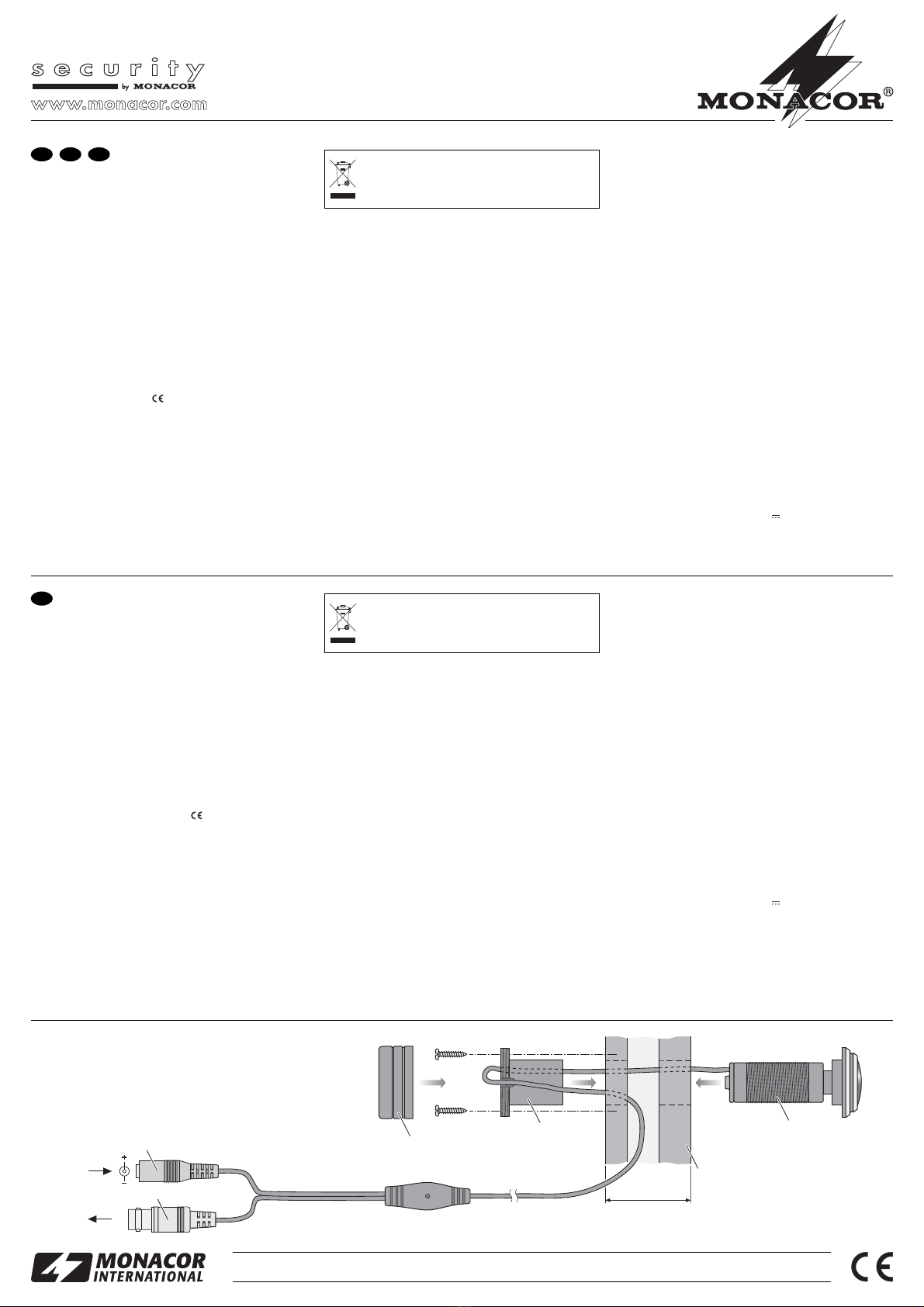
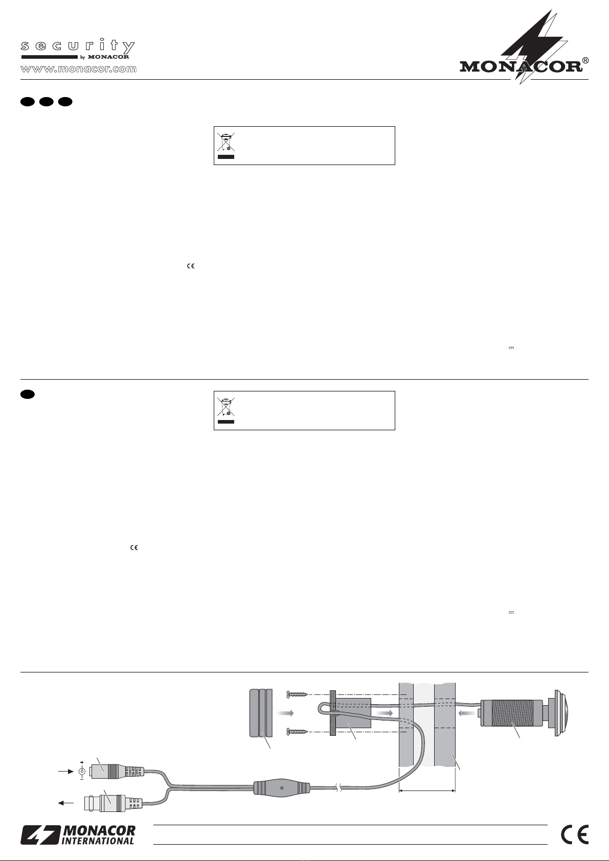
1) Haga un agujero de 21 mm de diámetro en la puer-
ta. Además, corte una muesca para pasar el cable.
2) Monte la cámara en la puerta por ejemplo tal como
se indica en el esquema. Atornille la rosca de mon-
taje (4) sobre la cámara (6) de tal manera que la
puerta (5) quede en el medio. Pase el cable dentro
la ranura lateral de la extremidad de la rosca de
montaje. No atornille la rosca de montaje hasta que
no haya probado el funcionamiento con la puerta.
3) Aplique el señal vídeo presente en la toma BNC
(2) vía un cable blindado en la entrada vídeo de un
monitor. Para un cable de longitud superior a
100 m, se recomienda instalar un amplificador
vídeo entre la cámara y el cable para compensar
las pérdidas en línea.
4) Conecte una alimentación estabilizada 12 V con
una capacidad de carga de al menos 110 mA (por
ejemplo PSS-600E de MONACOR) a la toma de
alimentación (1). Una toma de baja tensión 5,5/
2,1 mm (diámetro exterior/diámetro interior) es ne-
Cuando la cámara está definitivamente reti-
rada del servicio, debe depositarla en una
fábrica de reciclaje próxima para contribuir a
su eliminación no contaminante.
cesaria. Procure respectar la polaridad: coloque el
polo positivo en el contacto del medio de la toma.
5) Una vez aplicada la tensión de funcionamiento,
encienda el monitor y oriente la cámara de mane-
ra que la imagen aparezca en el monitor de mane-
ra correcta. Atornille seguidamente la rosca de
montaje (4) en la puerta. Atornille la tapa (3) sobre
la extremidad de la rosca de montaje: procure que
el cable pase dentro de la ranura lateral de la
extremidad.
4 Características técnicas
Óptica: . . . . . . . . . . . . . . CCD, 8,5 mm (1/3″)
Sistema vídeo: . . . . . . . CCIR, hor. 15 625 Hz,
vert. 50 Hz
Píxeles: . . . . . . . . . . . . . hor. 500 × vert. 582
Resolución: . . . . . . . . . . 400 líneas
Objetivo: . . . . . . . . . . . . 1 : 1,2/1,78 mm
Obturación: . . . . . . . . . . 1/50 s á 1/100 000 s
Luminosidad mínima: . . 0,01 lux
Factor de corrección
gama: . . . . . . . . . . . . . . 0,45
Relación señal/ruido: . . > 45 dB
Salida vídeo: . . . . . . . . . 1 Vcc/75 Ω
Temperatura func.: . . . . 0 – 40 °C
Alimentación: . . . . . . . . 12 V /110 mA
Nos reservamos el derecho de modificación.
TVCCD-119 Best.-Nr. 19.0280
Kamera czarno-biała
Prosimy o uważne przeczytanie poniższej instrukcji
przed użyciem urządzenia oraz o zachowanie tekstu
do wglądu.
1 Zastosowanie
Szerokokątna kamera jest przeznaczona do użytku w
systemach nadzoru jako wizjer. Kamerę można zain-
stalować w drzwiach o grubości od 42 mm do 66 mm.
Posiada elektroniczną migawkę i automatyczną regu-
lację wzmocnienia (AGC).
2 Informacje dotyczące bezpieczeństwa
Ponieważ urządzenie spełnia wszelkie normy obowią-
zujące w Unii Europejskiej, zostało oznaczone sym-
bolem .
GUrządzenie należy chronić przed wodą, wysoką wil-
gotnością i wysoką temperaturą (dopuszczalny
zakres temperatury to 0 – 40 °C).
GNie dotykać obiektywu palcami. Do czyszczenia
obiektywu stosować tylko odpowiednie preparaty
do szkieł optycznych.
GProducent ani dostawca nie ponosi odpowiedzial-
ności za wynikłe szkody materialne, jeśli urządze-
nie było używane niezgodnie z przeznaczeniem,
zostało zainstalowane lub obsługiwane niepopraw-
nie lub poddawane nieautoryzowanym naprawom.
3 Obsługa
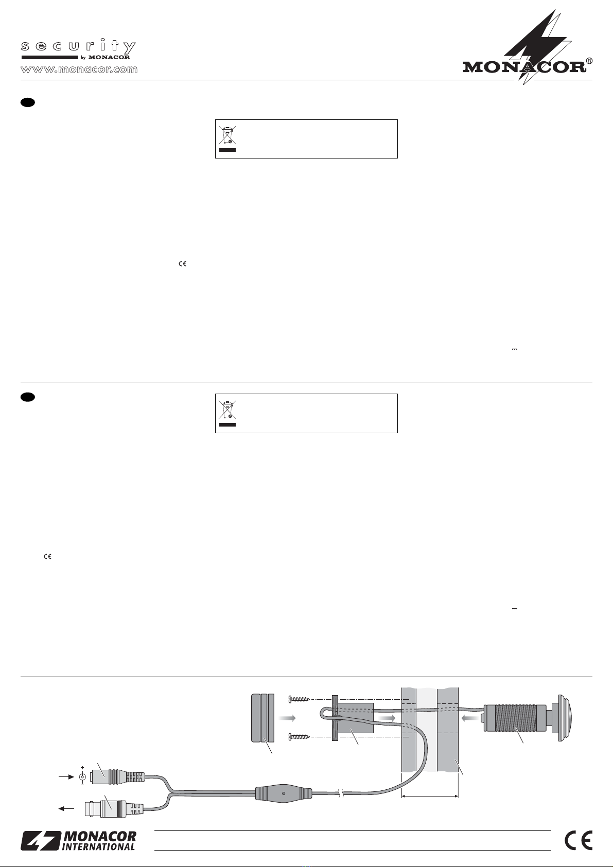
1) W drzwiach należy wywiercić otwór o średnicy
21 mm. Dodatkowo, zrobić wycięcie na kabel.
2) Zamontować kamerę w drzwiach zgodnie ze wska-
zówkami na rysunku. Przykręcić tuleję (4) i kame-
rę (6) tak żeby razem obejmowały drzwi (5). Umie-
ścić kabel w rowku znajdującym się na kołnierzu
tulei. Przeprowadzić test kamery przed dokręce-
niem tulei do drzwi.
3) Podłączyć wtyk BNC (2) za pomocą ekranowane-
go kabla do wejścia wideo monitora. Jeśli długość
kabla przekracza 100 m, należy zainstalować
wzmacniacz wideo pomiędzy kamerą i kablem w
celu skompensowania strat związanych z długim
okablowaniem.
4) Podłączyć zasilacz o wyjściowym napięciu 12 V, o
wydajności przynajmniej 110 mA (np. PSS-600E z
oferty MONACOR) do gniazda nakablowego (1).
Należy zastosować niskonapięciową wtyczkę o
wymiarach 5,5/2,1 mm (średnica wewnętrzna/
zewnętrzna). Proszę zawsze przestrzegać odpo-
wiedniej biegunowości: biegun dodatni powinien
znajdować się na wewnętrznym styku wtyczki.
Jeśli urządzenie nie będzie już nigdy więcej
używane, wskazane jest przekazanie go do
miejsca utylizacji odpadów, aby zostało utyli-
zowane bez szkody dla środowiska.
5) Po włączeniu zasilania, włączyć monitor i ustawić
kamerę tak, żeby obraz na monitorze był prawidło-
wo wyświetlany, następnie dokręć śrubami tuleję
(4) do drzwi. Przykręcić osłonę (3) tulei. Należy
dopilnować, żeby kabel znajdował się w rowku koł-
nierza tulei.
4 Dane techniczne
Przetwornik obrazu: . . . chip CCD, 8,5 mm (1/3″)
System wideo: . . . . . . . CCIR, poz. 15 625 Hz,
pion. 50 Hz
Liczba pikseli: . . . . . . . . poz. 500 × pion. 582
Rozdzielczość: . . . . . . . 400 linii
Obiektyw: . . . . . . . . . . . 1 : 1,2/1,78 mm
Migawka: . . . . . . . . . . . . 1/50 s do 1/100 000 s
Minimalne oświetlenie: . 0,01 lux
Współczynnik gamma: . 0,45
Stosunek S/N: . . . . . . . . > 45 dB
Wyjście wideo: . . . . . . . 1 Vpp/75 Ω
Dopuszczalna
temperatura pracy: . . . . 0 – 40 °C
Zasilanie: . . . . . . . . . . . . 12 V /110 mA
Z zastrzeżeniem do możliwych zmian.
E
PL
12V
Video
13
4
5
min. 42 mm
max. 66 mm
6
2
®
MONACOR INTERNATIONAL GmbH & Co. KG • Zum Falsch 36 • 28307 Bremen • Germany
Copyright©by MONACOR INTERNATIONAL. All rights reserved. A-0380.99.02.06.2012
®

This manual suits for next models

1

Other Monacor Digital Camera manuals

Monacor security TVCCD-92AP User manual

Monacor

Monacor security TVCCD-92AP User manual

Monacor TVCCD-124 User manual

Monacor

Monacor TVCCD-124 User manual

Monacor TVCCD-95 User manual

Monacor

Monacor TVCCD-95 User manual

Monacor TVCCD-310 User manual

Monacor

Monacor TVCCD-310 User manual

Monacor AV-420SET User manual

Monacor

Monacor AV-420SET User manual

Monacor TVCCD-92A User manual

Monacor

Monacor TVCCD-92A User manual

Monacor TVCCD-92AP User manual

Monacor

Monacor TVCCD-92AP User manual

Monacor TVC-500 User manual

Monacor

Monacor TVC-500 User manual

Monacor INC-4312BBVM User manual

Monacor

Monacor INC-4312BBVM User manual

Monacor TVCCD-302 User manual

Monacor

Monacor TVCCD-302 User manual

Popular Digital Camera manuals by other brands

Olympus EVOLT E-330 Specifications

Olympus

Olympus EVOLT E-330 Specifications

Samsung i8 manual

Samsung

Samsung i8 manual

VPixx Technologies VideoBahn TRACKPixx3 installation guide

VPixx Technologies

VPixx Technologies VideoBahn TRACKPixx3 installation guide

BenQ DC 5330 user manual

BenQ

BenQ DC 5330 user manual

Panasonic DMC-FT1EB Service manual

Panasonic

Panasonic DMC-FT1EB Service manual

Minolta MND50 user manual

Minolta

Minolta MND50 user manual

Rollei dsx410 instruction manual

Rollei

Rollei dsx410 instruction manual

FujiFilm FinePix S1500 owner's manual

FujiFilm

FujiFilm FinePix S1500 owner's manual

Casio Exilim EX-Z600 Service Manual & Parts Guide

Casio

Casio Exilim EX-Z600 Service Manual & Parts Guide

Concord Camera Eye-Q 3103 Frequently asked questions

Concord Camera

Concord Camera Eye-Q 3103 Frequently asked questions

Panasonic Lumix DMC-G3K Basic operating instructions

Panasonic

Panasonic Lumix DMC-G3K Basic operating instructions

Axis XPQ1785 user manual

Axis

Axis XPQ1785 user manual

Casio Exilim EX-FC200S user guide

Casio

Casio Exilim EX-FC200S user guide

Samsung SAMSUNG MV800 user manual

Samsung

Samsung SAMSUNG MV800 user manual

Sony Mavica MVC-FD85 Service manual

Sony

Sony Mavica MVC-FD85 Service manual

Kodak STEP Touch user guide

Kodak

Kodak STEP Touch user guide

Canon POWERSHOT SX240 HS user guide

Canon

Canon POWERSHOT SX240 HS user guide

Kodak Pixpro AZ651 user manual

Kodak

Kodak Pixpro AZ651 user manual

manuals.online logo
manuals.online logoBrands
  • About & Mission
  • Contact us
  • Privacy Policy
  • Terms and Conditions

Copyright 2025 Manuals.Online. All Rights Reserved.