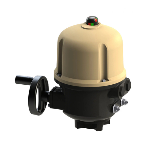
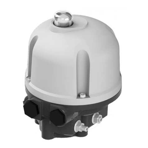
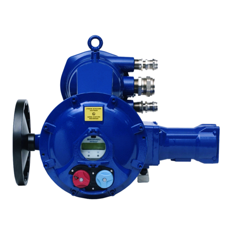
Bernard Controls AQ Series User guide

1
AQ SWITCH
RANGE
Start Up Guide
Instructions de mise en service
SUG_17003 - Ind. A
Art : 5100466

TABLE OF LANGUAGES
1 English -------------------------------------------------- 3
2 Français -------------------------------------------------- 3
3 Español -------------------------------------------------- 5
4 Italiana --------------------------------------------------- 7
5 Deutsch--------------------------------------------------- 7
2
58
44
30
16
3

2
TABLE OF CONTENTS
1SAFETY ---------------------------------------------------------- 3
2PACKAGING, STORAGE AND MAINTENANCE-----------------3
Packaging
Storage
Maintenance
3ASSEMBLY ------------------------------------------------------- 5
Changing closing direction indication
4EMERGENCY HANDWHEEL OPERATION ---------------------- 6
5ELECTRICAL COMMISSIONNING ------------------------------- 6
5.1 Connection and preliminary tests
5.2 Position feedback potentiometer (OPTION)
5.3 TAM position transmitter (OPTION)
5.4 Heating resistor
6TRAVEL LIMIT SETTINGS------------------------------------- 11
Single cam setting
Cams and mechanical stops setting
7TORQUE LIMITING DEVICE (AQ25 / 30 / 50 only) -------- 14
3
4
12
15
7
7
6
4

English
3
1SAFETY
This device complies with current applicable safety standards.
Installation, maintenance and useofthis unitrequire a skilled and
trained staff.
Please carefully readthis whole document before mounting and
starting-up the actuator.
2PACKAGING, STORAGE AND MAINTENANCE
Packaging
AQ actuators are delivered in a cardboard box of a size equivalent to
the actuator and sit in a cardboard wedge.
Storage
Actuators should be stored under a shelter, in a clean and dry place
and protected from wide temperature variations.
•Avoid placing the actuator directly on the floor.
•Check that plugs on cable entries are correctly tightened.
•Check that cover screws are correctly tightened to ensure
weatherproof sealing of the cover.
AQ actuators include electrical components and lubricated gears.
Even with a weatherproof enclosure, oxidation, seizing and other
alterations may occur if actuatorsare not correctly stored.
What to check after storage
1. Visually check the electrical equipment.
2. Manually operate micro-switches, buttons, selectors, etc., to
ensure their proper mechanical functioning.
3. Manually operate the actuator.
Heating element should be connected to power supply especially
if the storage place is wet (standard 230 VAC, except
otherwise specified).
4

English
4
What to check on installed non-commissioned actuators
If you expect a long period between actuator mounting and electrical
wiring:
1. Visually check that cable entries and cover are tightly closed.
2. In case of outdoor installation, cover the unit with a plastic
protective film.
Actuators equipped with electronic components
Long term storage ofelectronic components which are notin service
increases the risk of malfunction. This is not advisable.
If a long term storage is absolutely necessary, westrongly
recommend a revision ofthe electronic boards inour factory
before actuatorusage.
Maintenance
This actuator features lifetime lubrication. While the device is
correctly mounted and sealed, nospecific maintenance is required.
Test once a year themotor operation and makesure that the
electrical compartment isfree from condensation.
If it operates in awet atmosphere, this actuatorincludes an anti-
condensation heater to avoid condensation build-up.
5

English
5
3 ASSEMBLY
Actuator shouldbe attached directly tothe valve using proper bolts
or via a proper interface.
After assembly, the actuator can operate in any position.
However:
•do not lift the actuator by the handwheel to avoid damage on
internal gearing
•cable glands must not be oriented upwards
(loss of water
tightness)
Changing closing direction indication
As a standard, AQ actuator is configured to close clockwise. If the
actuator must close counter-clockwise, you can change
orientation ofthe position indicator cap.
Standard indicator orientation
for clockwise closing
Reverse indicator orientation
for counter-clockwise closing
How to change cap orientation
1. Disassemble the cover then the cap.
2. Turn the cap 90°.
3. Reassemble the cap then the cover.
6

English
6
4EMERGENCY HANDWHEEL OPERATION
AQ actuators feature a handwheel for emergency operation.
To avoid potentially harmful turning protruding parts during
electrical operation, AQhandwheels feature afoldable handle: you
can fold it duringelectrical operation and unfold it if you need to
operate the actuator manually.
5ELECTRICAL COMMISSIONNING
Connection and preliminary tests
8- Capacitor
7- Switches board
6- Torque limiter
5- Motor
4– Heating resistance
3- Cams
2- Terminal block
1- Position indicator
Actuator and its components are wired to internal terminal blocks.
To proceed to the wiring, remove the cover and pass the cables
throughthe M20 cable entries or ¾” NPTcable entries
(depending onorder).
Please refer to the wiring diagram enclosed for terminal numbering.
Both thermal protector and torque limit switches must be integrated
into yourcontrol system inorder toprevent potential damage to the
actuator or valve.
7

English
7
What to check after wiring
Once actuator wiring is completed,please check the following:
1. Make sure that power supply voltage matches information on
the sticker on the side of the actuator.
2. Check that all connectors or cable glands are correctly
tightened.
3. Manually drive the valve to a mid-travel position.
4. Electrically operate counter-clockwise rotation and check that
the motor rotates in the right direction.
5. Manually press on the counter-clockwise travel limit switch
then the motor should stop.
6. Repeat steps 4 and 5 for clockwise direction.
•If any fault is detected at this stage, please check again the
whole wiring.
Position feedback potentiometer (OPTION)
The potentiometer used for actuator
position feedback isdriven by the travel
cam block system.
For clockwise closing:
•0% position indicates a closed valve
•100% position indicates an open valve.
Resistance value is measured between 16 and 17 terminals.
8
Potentionmeter

English
8
How to set the potentiometer circuit board
You can set the zero of the potentiometer with the 0% position
screw.Use a flat blade screwdriver toturn this screw.
1. Drive the actuator to the CLOSED position.
2. Untighten the positioner pinion blocking screw.
3. Adjust the potentiometer by turning its shaft so that the
resistance value exceeds 0 Ohm and regularly increases then
turn backwards to reach the closest value to 0 Ohm. Tighten
back the positioner pinion blocking screw.
4. Drive the actuator to the OPEN position and write down the
resistance value corresponding to the 100% position.
5. Come back to the CLOSED position and check that the
resistance shows a repeatable near zero value for the 0%
position.
Signal inversion
To change the signal variation direction, invert potentiometer wires
on the terminal block (e.g. for a connection on16/17/18,
invert 16and 18).
Position feedback potentiometer (Left) & TAM position transmitter (Right)
9

English
9
TAM position transmitter (OPTION)
The TAM transmitter delivers a 4 to 20mA signal linearly proportional
to the angular position of the valve.
Electrical connections
To connect TAM, refer tothe wiring diagram supplied.
Filtered or stabilized power supply should be provided within the 12
to 32 VDC range. Maximumadmissible resistance valuesare given
in the following table:
DC supply
(volts)
Max. admissible resistance
(ohms)
12 150
24 750
32 1050
Signal direction inversion
The TAM transmitter, when supplied with a clockwise closing
actuator, provides a signal that rise from close position toopen
position.
If an opposite signal variation is required, simply move 2 jumpers on
the board near the potentiometer:
•direct signal: jumpers on 1-3 and 2-4
•reversed signal: jumpers on 1-2 and 3-4
10
Position transmitter
0/4-20mA

English
10
How to set TAM
1. Connect a milli-amp meter on terminal block.
2. Always start by adjusting the 4mA.
3. Drive actuator to the position corresponding to the 4 mA
(CLOSED position).
4. Untighten the potentiometer pinion blocking screw. Adjust the
potentiometer shaft so that the output current reaches a
minimum value.
5. Turn backwards until the current value regularly increases
then turn backwards again and stop as soon as the minimum
value determined here above is reached and tighten back the
potentiometer pinion blocking screw.
The potentiometer is then positioned at the very beginning of
its track.
6. Then, use the TAM adjustment screw marked as 0/4mA to
adjust the current to a value as close to the 4 mA as possible.
7. Drive actuator to the position corresponding to the 20 mA
(open position).
8. Turn the screw marked 20mA in order to read exactly 20 mA
on the milli-amp meter.
9. Come back to the closed position and check that, for the 0%
position, the signal current shows a close to 4 mA and
repeatable value.
11

English
11
5.4 Heating element
Each actuator includes a heating resistor.
As soon as the actuator is installed inthe field, itisrecommended
to power the resistor to prevent condensation.
•Immediately put the cover back in place after start-up while
ensuring its seal is clean.
Never leave actuator electrical
components without their protection cover.
In case of water intrusion:
•Dry electrical components before putting back the cover.
•Check electrical insulation.
6TRAVEL LIMIT SETTINGS
The actuator is factory-set for a 90°travel.
It features 2 devices to limit the travel:
•Cams trigger switches to switch off power at an end position or
to signal a position
•Mechanical stops mechanically block rotation to protect the valve
in case of over-travel. They must not be used as travel limits.
Single cam setting
The cam rotates with the
output shaft and
triggers a switch by
pushing on its lever.
Cams orientation are factory
pre-set, yet you can still
re-adjust them
during the commissioning
if necessary.
Rep. Function Status before installation
1
Clockwise travel limit
Pre-wired, cam pre-set
2
Counter-clockwise travel limit
Pre-wired, cam pre-set
3
Clockwise signaling
To wire, to set
4
Counter-clockwise signaling
To wire, to set
12

English
12
How to adjust a single cam
At the desired position of the actuator output:
1) Turn the setting screw of
the corresponding cam
with a flat blade
or a
Phillips screwdriver.
cam disk is then turning.
2) Set the cam disk until you
hear a click from the
switch. It indicates the
trigger of the switch.
Cams and mechanical stops setting
On AQswitch actuators, bothcams and mechanical stops can be set.
The actuator stops on open andclosed position when the travel limit
switch is tripped.
Travel limit settings
The mechanical stops (1:counter-
clockwise –2: clockwise)
avoid over-travel in case of
handwheel operation.
They can be set on the actuator or
on the gearbox ifa gearbox is
fitted onthe actuator.
Fine adjustment of the stop
screws position is possible
within a limit of ± 2°
maximum. These screws
are located on the lower side of the actuator.
Take care that cams get to the lever according to its inclination
direction, otherwise you could damage the switch.
If the actuator is supplied mounted on avalve,
following settings should have been performed by the
valve
supplier.
13

English
13
How to adjust cams and mechanical stops for both directions
One turn of the adjustment screw = 4° angle variation at
the actuator output.
Clockwise mechanical stop setting
1. Untighten the nut corresponding to clockwise mechanical
stop and turn the mechanical stop 2 turns back.
2. Drive the actuator to clockwise travel limit position.
3. Get the clockwise mechanical stop in contact with output
sleeve then move it back of 1.5 turns.
4. Retighten nut to keep mechanical stop in position.
Clockwise travel limit switch cam setting
5. Set the cam corresponding to clockwise travel limit switch.
Clockwise signaling switch cam setting (if wired)
6. Drive slightly the output in the counter-clockwise direction
using manual override.
7. Set the cam corresponding to clockwise signaling switch.
Counter-clockwise settings
8. Untighten the nut corresponding to counter-clockwise
mechanical stop and turn the mechanical stop 2 turns back.
9. Drive the actuator to the counter-clockwise travel limit
position.
10. Redo settings steps 3 to 7 for counter-clockwise direction.
Perform complete electrical valve opening and closing operations. It
is mandatory that the motor stops on the travel limit switch and
not on the mechanical stop (check available extra travel to the
stop with handwheel).
14

English
14
7TORQUE LIMITING DEVICE (AQ25 / 30 / 50 only)
The actuator is protected by a torque limiting device in case of over-
torque.
If the actuator stops in a position which is notthe one
desired, pleasecheck if actuatordidnot reach
mechanical stops or that valve has no stiff point.
Actuators are set and tested in factory according to torque stated on
orders. If no torque is specified, the actuator is supplied with
limiter set to the maximum output torque. In both of these
cases, you can adjust torque limiter if necessary.
Torque limiter operation
Please check below torque limiter setting components.
5– Clockwise direction
cam
4– Clockwise direction
switch
3– Counter-clockwise
direction cam
2– Counter-clockwise
direction switch
1– Torque scale disk
Torquelimiter is triggered as (3)and (5)cams trigger their
corresponding (2) and (4)switches when rotating.
Torque scale disk (1)allows toset torque limit for both directions.
It has torque graduations from 40 to 100%of the maximum
torque deliverable by the actuator.
To adjust torque, set the tip of cam to match the torque
percentage desired on the disk.
Torque scale disk is factory-set andis a reference for cams setting.
Do not modify its position oryou will not beable to set the
torque limiteraccurately.
15

2
SOMMAIRE
1SÉCURITÉ-------------------------------------------------------- 3
2EMBALLAGE, STOCKAGE ET MAINTENANCE ----------------- 3
Emballage
Stockage
Maintenance
3ASSEMBLAGE ---------------------------------------------------- 5
Modifier l'indication de direction de fermeture
4MANOEUVRE D’URGENCE-------------------------------------- 6
5MISE EN SERVICE ÉLECTRIQUE-------------------------------- 6
5.1 Connexion et tests préliminaires
5.2 Potentiomètre de recopie de position (OPTION)
5.3 Transmetteur de position TAM (OPTION)
5.4 Résistance de chauffage
6RÉGLAGES DES FIN-DE-COURSE---------------------------- 11
Réglage d’une came seule
Réglage des cames et des butées mécaniques
7LIMITEUR DE COUPLE (AQ 25/30/50 seulement) -------- 14
17
16
28
25
20
20
19
17

Français
3
1SÉCURITÉ
Cet appareil est conforme aux normes de sécurité applicables.
L'installation, la maintenance et l'utilisation de cet appareil doivent
être exécutés par un personnel qualifié et entraîné.
Veuillez lire attentivement tout ce document avant de monter et
démarrer l'actionneur.
2EMBALLAGE, STOCKAGE ET MAINTENANCE
Emballage
Les actionneurs AQ sont livrés dans une boîte en carton d'une taille
équivalente à l'actionneur et reposent sur une cale en carton.
Stockage
Les actionneurs doivent être stockés sous abri, dans un endroit
propre et sec, et protégés des grandes variations de température.
•Évitez de placer l'actionneur directement sur le sol.
•Vérifiez que les bouchons sur les entrées des
câbles sont
correctement serrés.
•Vé
rifiez que les vis du couvercle sont bien serrées pour
assurer l’étanchéité du couvercle aux intempéries.
Les actionneurs AQ comprennent des composants électriques et des
engrenages lubrifiés. Même avec un boîtier résistant aux
intempéries, l'oxydation, le grippage et d'autres altérations
peuvent se produire si les actionneurs ne sont pas correctement
stockés.
Que vérifier après stockage
1. Inspectez visuellement le matériel électrique.
2. Manœuvrez manuellement les micro-contacts, les boutons,
les sélecteurs, etc…, pour confirmer leur bon fonctionnement
mécanique.
3. Manœuvrez manuellement l'actionneur.
Une résistance de chauffage doit être branchéesur
l’alimentation électrique (230 VAC standard, sauf indication
contraire), en particulier si le lieu de stockage est humide.
17

Français
4
Que vérifier sur les actionneurs installés mais non câblés
Si vous prévoyez une longue période entre le montage de
l'actionneur et le câblage électrique:
1. Vérifiez visuellement que les entrées de câble et le
couvercle sont bien clos.
2. En cas d'installation en extérieur,couvrez l'appareil avec un
film plastique protecteur.
Actionneurs équipés d’éléments électroniques
Le stockage à long terme des composants électroniques qui ne sont
pas en service est déconseillé, cela augmente les risques de
dysfonctionnements.
Si un stockage à long terme est absolument nécessaire, nous
recommandons fortement une révision des cartes électroniques
dans notre usine avant l'utilisation de l'actionneur.
Maintenance
Cet actionneur est lubrifiéà vie. Tant que l'appareil est
correctement monté et étanché, aucune maintenance spécifique
n'est requise.
Testez le fonctionnement du moteur une fois par an et assurez-
vous que le compartiment électrique est exempt de condensation.
S’il fonctionne dans une atmosphère humide, cet actionneur
comprend une résistance anti-condensation pour éviter qu’elle ne
s’accumule.
18

Français
5
3ASSEMBLAGE
L'actionneur doit être fixé directement à la vanne en utilisant les
boulons appropriés ou via une interface appropriée.
Après l'assemblage, l'actionneur peut fonctionner dans n'importe
quelle position.
Cependant:
•
Ne pas soulever l'actionneur par le volant pour éviter
d'endommager la pignonnerie.
•Les presse-étoupes ne doivent pas être orientés vers le haut
(perte d'étanchéité à l'eau).
Modifier l'indication de direction de fermeture
Un actionneur AQ standard est configuré pour se fermer dans le
sens horaire. Si l'actionneur doit se fermer dans le sens anti-horaire,
vous pouvez modifier l'orientation du capuchon indicateur de
position.
Orientationstandard de
l'indicateur
Pour la fermeture dans le sens
horaire
Orientation inverse de
l'indicateur
Pour la fermeture dansle sensanti-
horaire
Comment changer l'orientation du
hublot
1. Démontez le couvercle puis le
hublot.
2. Tournez le hublot à 90°.
3. Remontez le hublot puis le
couvercle.
19

Français
6
4MANOEUVRE D’URGENCE
Les actionneurs AQcomportent un volant pour les manœuvres
d’urgence.
Pour éviter tout risque de dommage dû à des pièces saillantes
tournantes pendant le fonctionnement électrique, les volants AQ
disposent d’une manivelle repliable : vous pouvez laplier en
fonctionnement électrique et ladéplier pour manœuvrer
l'actionneur manuellement.
5MISE ENSERVICE ÉLECTRIQUE
5.1 Connexion et tests préliminaires
1- Indicateur de position
2- Bornier
3- Cames
4- Résistance de
chauffage
5- Moteur
6- Limiteur de couple
7– Limiteur de position
8 – Condensateur
L'actionneur et ses composants sont câblés sur les borniers internes.
Pour procéder aucâblage, retirez le couvercleet passez les
câbles par les entrées de câbleM20.
Reportez-vousau schéma de câblage joint pour la numérotation
des bornes.
La protection thermique et les contacts du limiteur de couple
doivent être intégrés dans votre système de commande afin
d'éviter des dommages potentiels sur l'actionneur ou la vanne.
20
Other manuals for AQ Series
1
This manual suits for next models
3
Table of contents
Languages:
Other Bernard Controls Switch manuals